


Create successful ePaper yourself
Turn your PDF publications into a flip-book with our unique Google optimized e-Paper software.
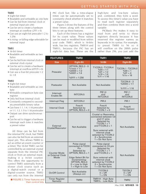
TMR0• Eight-bit timer• Readable and writeable as one byte• Can be fed from internal clock orexternal input pin (A4)• Can be set to create a hardwareinterrupt at overflow (255 > 0)• Can use an eight-bit prescaler 1:2 to1:256• Is rising- or falling-edge selectable forexternal inputTMR1• 16-bit timer• Readable and writeable as twobytes• Can be fed from internal clock orexternal clock crystal• Can be set to create a hardwareinterrupt at overflow (65535 > 0)• Can use a four-bit prescaler 1:2to 1:8TMR2• Eight-bit timer• Readable and writeable as onebyte• Writeable comparison byte sizeregister• Only fed from internal clock• Constantly compared to secondarypresettable binary value• Can have 1:1, 1:4, 1:16 prescaleror 1:1, 1:2, 1:3 to 1:16 postscaler• Output can drive synchronousport• Can be set to trigger a hardwareinterrupt each time it matchesa preset valueAll three can be fed fromthe internal PIC clock, but TMR0can also be fed from an externalinput pin. This allows TMR0 toact as either an event counter ora timer. The 16-bit TMR1 can becontrolled by an external crystalseparate from the internal PICclock or from an external input,making it a 16-bit counter.This offers the opportunity tocontrol TMR1 externally from aslower clock source such asa digital-watch crystal or adigital-counter source. TMR2can only run from the internal■ FIGURE 2. Timer features andtheir control bits.PIC clock but, like a time-elapsetimer, can be automatically set toconstantly check whether it matchesa preset value.Figure 2 shows the features of thethree timers along with the controlbits to set up these features.Each of the timers has a registerfor its count value. These valuescan be read or modified from withinyour code. TMR1, which is 16-bitswide, has two registers, TMR1H andTMR1L, because the PIC has aneight-bit data bus. These are theGETTING STARTED WITH PICshigh-byte and low-byte valuesand, combined, they form a word.To access this timer’s value you haveto read each register separatelyand then combine them into a wordvariable.PICBasic Pro makes it easy toread from and write to theseregisters directly because it hasreserved the register names askeywords in its syntax. For example,to preset TMR0 to 56 so itwill overflow on the 200th pulserather than 256, you just add theFEATURES TMR0 TMR1 TMR2Size Eight-Bit 16-Bit Eight-BitPrescalerOPTION_REG.3 - 0%1xxx = 1:1%0000 = 1:2%0001 = 1:4:%0111 = 1:256T1CON.5 -T1CON.4%00 = 1:1%01 = 1:2%10 = 1:4%11 = 1:16Postscaler Not Available Not AvailableInterruptEnable BitINTCON.5PIE1.0andINTCON.6T2CON.1 -T2CON.0%00 = 1%01 = 4%1x = 16T2CON.6 - 3%0000 = 1:1:%1111 = 1:16PIE1.1andINTCON.6Interrupt Flag INTCON.2 PIR.0 PIR.1Internal ClockExternalCrystal/ResonatorCounter Modeor External ClockModeOn/Off ControlTimer RegisterName(s)Fosc/4Selected byOPTION_REG.5 = 0Not AvailablePulse signalconnected to TOCKIPinSelected byOPTION_REG.5 = 1Edge Select Bit forIncrementing:OPTION_REG.40 = Low to High1 = High to LowNot Available(Always on)TMR0Fosc/4Selected byT1CON.1 = 0Crystal or Resonatorconnected between C0and C1 pinsSelected byT1CON.1 = 1and T1CON.3 = 1Sync external withinternal clockselected by T1CON.20 = Synchronize1 = Do Not SyncPulse signalconnected to C0 pinSelected byT1CON.1 = 1and T1CON.3 = 1Sync external withinternal clockselected by T1CON.20 = Synchronize1 = Do Not SyncT1CON.00 = Off1 = ONTMR1H - High ByteTMR1L - Low ByteFosc/4(Only Option)Not AvailableNot AvailableT2CON.20 = Off1 = ONTMR2May 2006 13


