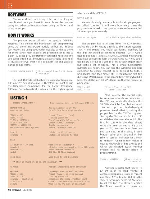
SOFTWAREThe code shown in Listing 1 is not that long orcomplicated once you break it down. Remember, we aredoing two advanced functions here: using the Timer1 andusing interrupts.HOW IT WORKSThe program starts off with the specific DEFINEsrequired. This defines the bootloader self programmingsetup that the Ultimate OEM module has built in. I know afew readers are using bootloader modules so this is therefor them. Since most readers are programming it into ablank PIC using a PIC programmer, you don’t need this lineso I commented it out by putting an apostrophe in front ofit. PICBasic Pro will treat it as a comment line and ignore itduring compile time.‘ DEFINE LOADER_USED 1 ‘ This command line for Ultimate‘ OEM onlyThe next DEFINE establishes the oscillator frequency.PICBasic Pro defaults to 4 MHz. Therefore, we must adjustthe time-based commands for the higher frequency.PICBasic Pro automatically adjusts for the higher speedwhen we add this DEFINE:DEFINE OSC 20We establish only one variable for this simple program.It’s called “counter.” It will store how many times theprogram interrupted so we can see when we have reached10 interrupts (one second).counter var byte‘Establish a byte size variableThe program has to initialize Timer1 to 3035 decimal,and we do that by writing directly to the Timer1 registers,TMR1H and TMR1L. You could use decimal numbers forthis, but that would be confusing because TMR1H wouldhave to be set to 11 and TMR1L to 219, and it’s not obviousthat these combine to form the word value 3035. You coulduse binary, setting all eight 1s or 0s in their proper order,but that’s a lot of typing. This is where hexadecimalnumbers are handy. You can use the Windows scientificcalculator to easily convert 3035 decimal to $0BDBhexadecimal and then make TMR1H equal to the first twodigits and TMR1L equal to the second two. That’s what I didhere. The dollar sign tells PICBasic Pro that the number isa hex value.TMR1H = $0B ‘Preset Timer 1 to 3035TMR1L = $DB‘ using $0BDB hexLISTING 1‘ DEFINE LOADER_USED 1 ‘ This command line for Ultimate OEM onlyDEFINE OSC 20‘Set oscillator to 20 MHzcounter var byte‘Establish a byte size variableTMR1H = $0B ‘Preset Timer 1 to 3035TMR1L = $DB‘ using $0BDB hexT1CON = %00110001‘Timer1 on with 1:8 prescalerPIE1 = %00000001‘Enable Timer1 InterruptINTCON = %11000000‘Enable interruptsON INTERRUPT GOTO mytimer ‘Define interrupt handlerhigh 2‘Initialize B2 LED to oncounter =0‘Initialize counter to zeromainif counter = 10 then‘Test for 10 interruptstoggle 2‘10 interrupts occurred so flip LED statecounter = 0‘Reset counter variableendif‘End the If-Then commandgoto main‘Loop back to the Beginning‘*** This is where we go on and interrupt ***Next, we enter the special registersetup commands. As mentioned,the PIC automatically divides the20 MHz clock by four, but we needto set up the divide-by-eightprescaler. We do that by setting theproper bits in the T1CON register.Setting the fifth and sixth bits to “1”establishes the prescaler as 1:8. Thefirst bit (bit 0 in the data sheet)turns the timer on (set to “1”) or off(set to “0”). We turn it on here. Asyou can see, in this case, I usedbinary rather than decimal or hex(the “%” symbol indicates it’s a binarynumber). Using binary makes iteasy to check which bits are set andwhich are cleared. Each numbersystem has its proper place inprogramming.T1CON = %00110001‘Timer1 on with‘ 1:8 prescalerdisablemytimer:TMR1H = $0BTMR1L = $DBcounter = counter +1PIR1.0 = 0resume16 May 2006‘Prevent interrupts from occurring‘Interrupt handler routine label‘Preset Timer 1 to 3035 decimal‘ using $0BDB hex‘Increment the timer overflow count‘Clear Timer1 overflow interrupt flag‘This is how we exit an interruptAnother register that needs tobe set up is the PIE1 register. Itcontrols peripherals such as Timer1and Timer2. The first bit (bit 0) is theTimer1 interrupt enable bit. We needto set this to “1” to allow or enablethe Timer1 overflow to cause an
GETTING STARTED WITH PICsinterrupt to the main program loop. I use binary againhere.PIE1 = %00000001‘Enable Timer1 InterruptInterrupts in the PIC are controlled from a key registercalled the INTCON register. There are two bits in theINTCON that enable the Timer1 interrupt. The seventh bit(bit 6) is the PEIE bit that enables any interrupts set inthe PIE1 register. The eighth bit (bit 7) is the GIE orGlobal Interrupt Enable bit that enables all interrupts.This is like a pecking order. All bits of these variousregisters have to be set for the Timer1 interrupt, but noneof them work until the top bit (GIE) is set. This is thecentral control bit that makes it easy to turn on or turn offall interrupts. You’ll see how PICBasic Pro also enables ordisables interrupts in sections of code using a PICBasicPro command. The bits are set, and easily seen, using abinary number.INTCON = %11000000‘Enable interruptsFinally, the label of where to jump to when theinterrupt or overflow occurs is defined as “mytimer.” Later,I’ll explain what we do when the interrupt actually occurs atthe “mytimer” label.ON INTERRUPT GOTO mytimer‘Define interrupt handlerBefore we get to the main loop, we start the LED inthe ON state by setting PortB’s bit 2 to a high value usingthe HIGH command. We also reset the “counter” variableto “0.”high 2counter =0‘Initialize B2 LED to on‘Initialize counter to zeroThe main section of code starts with the label“main.” This section is really simple. It checks whetherthe variable “counter” is equal to 10 yet. If it isn’t, theprogram just loops back and does it again. If, however,the value is equal to 10, then we want to change the stateof the LED, and we use the TOGGLE command to dothat. TOGGLE just switches it from OFF to ON orfrom ON to OFF. Then we reset the “counter” variableto “0” and end the IF-THEN statement with the ENDIFcommand.From there, we loop back to “main” to test “counter”again.The last section of code is the interrupt code andis separate from the main loop of code. When theinterrupt occurs, the program will finish whatevercommand was being executed, then jump to the definedinterrupt label, which is “mytimer” in this example. Notethat I said the program will finish its command beforejumping to the interrupt label. PICBasic Pro doesn’timplement true hardware interrupts unless you writethe interrupt routine in assembly and do someother advanced setup functions. Therefore, it offers twoforms of interrupt: simple and complex. Simple worksfor most examples, and it works here. That’s why I’musing it.The simple interrupt method has one drawback andthat is delay time of the commands. If you have acommand such as PAUSE 5000 in your main loop and itreceives an interrupt, the program will not jump to theinterrupt service routine until the full five seconds ofpause have occurred. Therefore, all commands should beshort when you use interrupts. A FOR-NEXT loop of 5000loops of PAUSE 1 would be a better way to achieve thesame result because it allows quicker interrupt response.This time delay before the interrupt code starts running isknown as interrupt latency. Interrupt latency is onedrawback of programming in Basic vs. programming inassembly.Before the “mytimer” label is the DISABLE command.This shuts off the Timer1 interrupt for any code belowthat command. This is necessary so the interrupt cannotoccur while we are running the interrupt routine. If weallowed that, we could end up in a continuous loop ofinterrupts and never leave the interrupt routine. Thisis also why it is very important to make your interruptroutines short so we don’t miss an interrupt whileprocessing one.disable‘Prevent interrupts from‘ occurringIn the interrupt service routine (or handler), we do twothings: reset Timer1 to 3035 and increment the “counter”variable. Remember, we check this variable to see ifit equals 10 in the main loop, but we increment it in theinterrupt service routine.mytimer:TMR1H = $0BTMR1L = $DBcounter = counter +1‘Interrupt handler routine label‘Preset Timer 1 to 3035 decimal‘ using $0BDB hex‘Increment the timer overflow‘ countmainif counter = 10 thentoggle 2counter = 0endifgoto main‘Test for 10 interrupts‘10 interrupts occurred so flip‘ LED state‘Reset counter variable‘End the If-Then command‘Loop back to the BeginningAt the end of the interrupt routine, we need to resetthe Timer1 overflow interrupt flag (TMR1IF) so we don’tinstantly jump back into an interrupt condition. We dothat by directly setting the PIR1 bit 0 to “0.” We follow thiswith the RESUME command, which is required byPICBasic Pro. This jumps the program back to the mainloop where it was interrupted. A GOTO command orRETURN command won’t work here. Interrupts require theMay 2006 17