You also want an ePaper? Increase the reach of your titles
YUMPU automatically turns print PDFs into web optimized ePapers that Google loves.
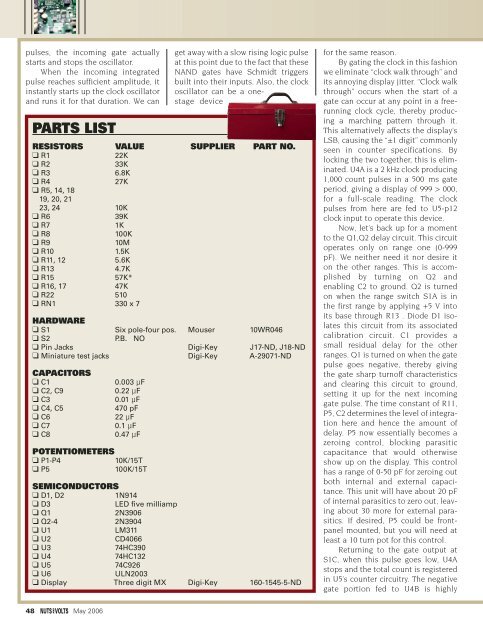
pulses, the incoming gate actuallystarts and stops the oscillator.When the incoming integratedpulse reaches sufficient amplitude, itinstantly starts up the clock oscillatorand runs it for that duration. We canPARTS LISTget away with a slow rising logic pulseat this point due to the fact that theseNAND gates have Schmidt triggersbuilt into their inputs. Also, the clockoscillator can be a onestagedeviceRESISTORS VALUE SUPPLIER PART NO.❑ R122K❑ R233K❑ R3 6.8K❑ R427K❑ R5, 14, 1819, 20, 2123, 24 10K❑ R639K❑ R71K❑ R8100K❑ R910M❑ R10 1.5K❑ R11, 12 5.6K❑ R13 4.7K❑ R15 57K*❑ R16, 1747K❑ R22 510❑ RN1 330 x 7HARDWARE❑ S1 Six pole-four pos. Mouser 10WR046❑ S2P.B. NO❑ Pin Jacks Digi-Key J17-ND, J18-ND❑ Miniature test jacks Digi-Key A-29071-NDCAPACITORS❑ C1❑ C2, C9❑ C3❑ C4, C5❑ C6❑ C7❑ C80.003 μF0.22 μF0.01 μF470 pF22 μF0.1 μF0.47 μFPOTENTIOMETERS❑ P1-P410K/15T❑ P5100K/15TSEMICONDUCTORS❑ D1, D21N914❑ D3LED five milliamp❑ Q12N3906❑ Q2-42N3904❑ U1LM311❑ U2CD4066❑ U374HC390❑ U474HC132❑ U574C926❑ U6ULN2003❑ Display Three digit MX Digi-Key 160-1545-5-NDfor the same reason.By gating the clock in this fashionwe eliminate “clock walk through” andits annoying display jitter. “Clock walkthrough” occurs when the start of agate can occur at any point in a freerunningclock cycle, thereby producinga marching pattern through it.This alternatively affects the display’sLSB, causing the “±1 digit” commonlyseen in counter specifications. Bylocking the two together, this is eliminated.U4A is a 2 kHz clock producing1,000 count pulses in a 500 ms gateperiod, giving a display of 999 > 000,for a full-scale reading. The clockpulses from here are fed to U5-p12clock input to operate this device.Now, let’s back up for a momentto the Q1,Q2 delay circuit. This circuitoperates only on range one (0-999pF). We neither need it nor desire iton the other ranges. This is accomplishedby turning on Q2 andenabling C2 to ground. Q2 is turnedon when the range switch S1A is inthe first range by applying +5 V intoits base through R13 . Diode D1 isolatesthis circuit from its associatedcalibration circuit. C1 provides asmall residual delay for the otherranges. Q1 is turned on when the gatepulse goes negative, thereby givingthe gate sharp turnoff characteristicsand clearing this circuit to ground,setting it up for the next incominggate pulse. The time constant of R11,P5, C2 determines the level of integrationhere and hence the amount ofdelay. P5 now essentially becomes azeroing control, blocking parasiticcapacitance that would otherwiseshow up on the display. This controlhas a range of 0-50 pF for zeroing outboth internal and external capacitance.This unit will have about 20 pFof internal parasitics to zero out, leavingabout 30 more for external parasitics.If desired, P5 could be frontpanelmounted, but you will need atleast a 10 turn pot for this control.Returning to the gate output atS1C, when this pulse goes low, U4Astops and the total count is registeredin U5’s counter circuitry. The negativegate portion fed to U4B is highly48 May 2006


