Marvac Fig. 121 (PV Valve) - Safety Systems UK Ltd
Marvac Fig. 121 (PV Valve) - Safety Systems UK Ltd
Marvac Fig. 121 (PV Valve) - Safety Systems UK Ltd
- No tags were found...

You also want an ePaper? Increase the reach of your titles
YUMPU automatically turns print PDFs into web optimized ePapers that Google loves.
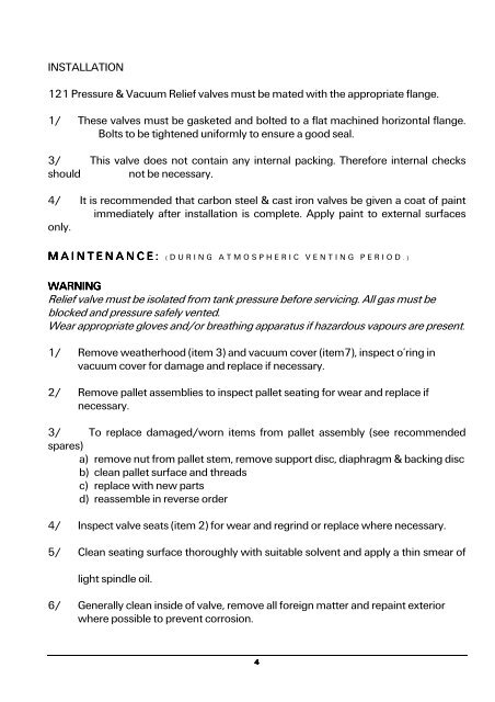
INSTALLATION<strong>121</strong> Pressure & Vacuum Relief valves must be mated with the appropriate flange.1/ These valves must be gasketed and bolted to a flat machined horizontal flange.Bolts to be tightened uniformly to ensure a good seal.3/ This valve does not contain any internal packing. Therefore internal checksshould not be necessary.4/ It is recommended that carbon steel & cast iron valves be given a coat of paintimmediately after installation is complete. Apply paint to external surfacesonly.M A I N T E N A N C E : ( D U R I N G A T M O S P H E R I C V E N T I N G P E R I O D . )WARNINGRelief valve must be isolated from tank pressure before servicing. All gas must beblocked and pressure safely vented.Wear appropriate gloves and/or breathing apparatus if hazardous vapours are present.1/ Remove weatherhood (item 3) and vacuum cover (item7), inspect o’ring invacuum cover for damage and replace if necessary.2/ Remove pallet assemblies to inspect pallet seating for wear and replace ifnecessary.3/ To replace damaged/worn items from pallet assembly (see recommendedspares)a) remove nut from pallet stem, remove support disc, diaphragm & backing discb) clean pallet surface and threadsc) replace with new partsd) reassemble in reverse order4/ Inspect valve seats (item 2) for wear and regrind or replace where necessary.5/ Clean seating surface thoroughly with suitable solvent and apply a thin smear oflight spindle oil.6/ Generally clean inside of valve, remove all foreign matter and repaint exteriorwhere possible to prevent corrosion.4


![ES139[IOM Fig 785 Marvac Emergency Relief Vent]](https://img.yumpu.com/43585698/1/190x245/es139iom-fig-785-marvac-emergency-relief-vent.jpg?quality=85)