General Specifications - Yokogawa
General Specifications - Yokogawa
General Specifications - Yokogawa

You also want an ePaper? Increase the reach of your titles
YUMPU automatically turns print PDFs into web optimized ePapers that Google loves.
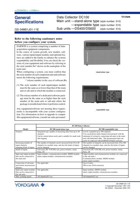
■ ConfigurationComponent unitsCH1CH2CH3CH4CH5CH6CH7CH8CH9CH10DC100 main unit stand-alone typeDC100 main unit expandable typeb -/B -/A b -/B -/ACH1CH2CH3CH4CH5CH6CH7CH8CH9CH10b -/B -/ACH1CH2CH3CH4CH5CH6CH7CH8CH9CH10CH1CH2CH3CH4CH5CH6CH7CH8CH9CH10CH1CH2CH3CH4CH5CH6CH7CH8CH9CH10b -/B -/Ab -/B -/A b -/B -/ACH1CH2CH3CH4CH5CH6CH7CH8CH9CH10b -/B -/ADS400 sub unitCH1CH2CH3CH4CH5CH6CH7CH8CH9CH10CH1CH2CH3CH4CH5CH6CH7CH8CH9CH10b -/B -/ADS600 sub unitSTATUSSUB UNITPOWER100-240VAC 50/60Hz 70VA MAXSTATUSSUB UNITPOWER100-240VAC 50/60Hz 70VA MAXUnit configurationDC100 stand-alone type:Stand-alone type main unit + various input/output modules +communication interface modulesDC100 expandable type:Expandable type main unit + sub units (DS400 or DS600)+ various input/output modules + communication interfaceCH1CH2CH3CH4CH5CH6CH7CH8CH9CH10b -/B -/AAvailable module groupsThe DC100 data collector can be freely configured for differentfunctions by selecting modules from the following module groups andconnecting them to the main or sub units.Input modules:Universal (DC voltage, thermocouple, RTD, contact), DC voltage,thermocouple, contact dedicated input modules, mA, powermonitor, strain, pulse, DI input.Alarm modules:4 point out put (transfer contact) or 10 point out put (make contact)(The number of alarm channels can be increased in module units.)Communications modules:Select one type from GP-IB, RS-232-C, RS-422-A/RS-485,Ethernet.DI/DO modules:Alarm 2-point output (transfer contact) and fail output modules andremote control signal input.Retransmission modules:Re-output of measured values and computed results.NOTERefer to “Standard connection modules” in GS 04M01E01-11E, orGS 04M01E01-50E for detailed specifications of the above modules.Package Software• DARWIN DAQ 32 (Standard Package)• DARWIN DAQ 32 Plus (Optional Package)<strong>General</strong>DAQ 32 and DAQ 32 Plus are software packages developed byYOKOGAWA specially for the DARWIN series.These packages run on a personal computer, achieving highlydependable data acquisition using DARWIN series units (DA100,DC100, DR130, DR230, and DR240) and superb operability.The main differences between the two packages are in themonitoring functions. The DAQ 32 only offers two display formats- waveform trend and digital; has 2 groups of 10 channels/window;and does not support alarm display. If simultaneous multi pointmonitoring or more flexible display forms of data such as levelmeter, analog meter, and thermometer faceplates, and alarmindications are required, use the optional DAQ 32 Plus.System RequirementsPersonal Computer: A personal computer running either aMicrosoft Windows 95, Windows 98, Windows NT 4.0, orWindows 2000 operating system.• For DAQ 32 (model code DP120-13), a pentium MMX 133 MHzor higher is required (pentium-II recommended) for the processor.• For DAQ 32 Plus (model code DP320-13), a pentium MMX 166MHz or higher is required (pentium-II recommended) for theprocessor.RAM:At least 32 megabytes (MB) (64 MB or largerrecommended)Hard Disk: 100 MB of free hard disk space is required forinstallation.The program size is 10 MB.NOTERefer to GS 04M01F02-11E or GS 04M01W01-11E for detailedspecifications of the above software package.GS 04M01J01-11E3
4DC100 stand-alone type system configurationSet-up and controlsoftwareInstallPersonal computer DARWINDAQ 32DARWINDAQ 32 Pluspackage softwareInTouchforDARWIN2000DAQLOGGERCommunicationinterface cableDC100 main unitModuleI/O moduleRetransmission moduleInput moduleCommunication interface moduleNo alarm module or DI/DO modulecan beconnected to therightside of this input module.Alarm outputmoduleDI/DOmodule1-5 V module4-20 mAmoduleUniversalDC V/TC/DImoduleDImodulePulsemodulePowermoduleStrainmodulemA(current)moduleGP-IBmoduleRS-232-CmoduleRS-422-A/485moduleEthernetmoduleGS 04M01J01-11EInputDC VTCRTDContact Status~ACAcurrentPULSESTRAIN
GS 04M01J01-11E5Alarm outputmoduleDC100 expandable type system configurationModuleI/O moduleDI/DOmoduleInputSet-up and controlsoftwareSub unit1-5 V moduleDARWINDAQ 32Retransmission moduleDCV4-20 mAmodulepackage softwareDARWINDAQ 32 PlusTCInTouchforDARWIN2000RemotemeasurementExtensionmoduleInstallDAQLOGGERUniversalDC V/TC/DImoduleRTDDImodulePowermoduleContact StatusInput moduleNo alarm module or DI/DO modulecan beconnected to therightside of this input module.Communicationinterface cablemA(current)moduleACPersonal computerDC100 main unitDedicated cable (up to 500m)~Pulse inputmoduleAcurrentStrainmoduleGP-IBmodulePULSERS-232-CmoduleSub unitCommunication interface moduleRS-422-A/485moduleSTRAINEthernetmodule
Sample Rate: 0.5 s, 1 s, 2 s, 3 s, 4 s, 5 s, 6 s, 10 s, 12 s, 15 s,20 s, 30 s, 1 min., 2 min., 3 min., 4 min., 5 min.,10 min., 30 min., or 60 min.LOGIC (event/action function)Recording Data Length in the Data Length Data AcquisitionMethod (unit: data item/channel):10, 20, 30, 40, 50, 100, 200, 300, 400, 500, 1 k,2 k, 3 k, 4 k, 5 k, 10 k, 20 k, 30 k, 40 k, 50 k,100 kStandard computation functionsComputation functions:Difference between arbitrary channels, linear scaling, movingaverage, pulse integration (when pulse module is installed)Scaling:Ranges for which scaling can be done:DC voltage, thermocouple, RTD, contact, strain,mA.Scaling range: –30000 to +30000Decimal point: Can be set freely.Measurement accuracy for scaling:Measurement accuracy for scaling (digits) =Measurement accuracy (digits) × Scaling span(digits)/Measurement span (digits) + 2 digits(Numbers below the decimal point are discarded.)Moving average:The moving average results for between 2 to 64 (2 n : n is nonnegativeinteger) scans are computed.Communications functionsCommunication modules:GP-IB, RS-232-C, RS-422-A/RS-485, Ethernet communicationsinterface modules.Output functionsDI/DO module:Internal alarm 2 points, fail, and file end output functionRetransmission modules:Re-output of measured values and computed resultsAC power supply sectionRated supply voltage:100 to 240 VAC (free supply voltage selection)Usable supply voltage range:90 to 250 VACRated supply frequency:50/60 HzPower consumption:Stand-alone type main unit(when 4 connectable modules are installed)max approx. 90 VADC power supply sectionRated supply voltage:12 to 28 VDCUsable supply voltage range:10 to 32 VDCPower consumption:max. approx 30 VA (DC100)max. approx 25 VA (DS400, DS600)Terminal: Dedicated connectorOthers: DC power supply only. However, whenpurchasing the DC100 DC power operationmodel, attached the dedicated AC adapter asstandard accessory.AC adapter for DC power modelRated supply voltage:100 to 240 VAC (free supply voltage selection)Usable supply voltage:90 to 250 VACRated supply frequency:50/60 HzPower consumption:max. approx 90 VAOthersClock: With calendar function (Western calendar),Clock accuracy is ±100 ppmSystem alarm: Contact output (when DI/DO module isconnected)Set value backup:Lithium battery backup (approx. 8 years),excluding clock functionInsulation resistance:At least 20 MΩ between each terminal andground (measured with 500 VDC)Withstand voltage:Between AC power supply terminal and case ofDC100 main unit: 1500 VAC (50/60 Hz) for oneminuteBetween DC power supply terminal and case ofDC100 main unit: 1000 VAC (50/60 Hz) for oneminuteBetween input terminal and case of DA100 mainunit:1500 VAC (50/60 Hz) for one minuteBetween output terminal and case of DA100main unit:2300 VAC (50/60 Hz) for one minuteExpandable type main unit(when 4 connectable modules are installed)max approx. 90 VADS400 sub unit(when 4 connectable input/output modules are installed)max approx. 55VADS600 sub unit(When 6 connectable input/output modules are installed)max approx. 70 VA8GS 04M01J01-11E
Normal operation conditionsSupply voltage: 90 to 250 VAC, 10 to 32 VDCSupply frequency: 50 Hz ± 2%, 60 Hz ± 2%Ambient temperature:Stand-alone type main unitexpandable type main unitWhen floor, Panal, Rack, mounted and Desk top: 5 to 40°CDS400/DS600 sub unitWhen floor-mounted and Desk top: 0 to 50°CWhen panel-mounted: –0 to 60°CWhen Rack-mounted: 0 to 50°CWhen DC operation: 0 to 50°CAmbient humidity:TemperatureHumidity–10 to 40˚C 20 to 80% RH40 to 50˚C 10 to 50% RH50 to 60˚C 5 to 30% RH* no ice formationVibration: 10 to 60 Hz 0.2 m/s 2Shock: Not allowedMagnetic field: 400 A/m max (50/60 Hz)Position: Mount the unit left-right horizontally orvertically, as a general rule.Warm-up time: At least 30 minutes after power switch-onStandard performanceReference operation state:23 ± 2°C, 55 ± 10% RH, supply voltage: 90 to250 VAC, supply frequency: 50/60 Hz ± 1%,Warmup: At least 30 minutes; When operating,the system must not adversely affect the operationof other measuring instruments by generatingvibration, for example. enerating vibration, forexample.NOTERefer to “Standard connection modules for the DC100 data collector”in GS 04M01E01-11E for detailed specifications of the measurementaccuracy.Signal source resistance:Variation with respect to signal source resistance+ 1 kΩ change(1) Voltage 2 V range or below ... Within ±10 µV6 V range or above ... Within ±0.1% of rdg(2) ThermocoupleWithin ±10 µV; However, it must be within ±100µ when burnout is specified.(3) RTD Variation with respect to change of 10 Ω per wire(when all three wires are the same resistancevalue)Indication ... Within ±(0.1% of rdg + 1 digit)Variation in indication with respect to adifference of 40 mΩ in the resistancebetween conductors (max difference between3 wires) ... Approx. 0.1°CMounting position:Variation when the unit is mounted horizontallyon a panel ... Within ±(0.1% of rdg + 1 digit)Vibration: Variation when sinusoidal vibration ofacceleration 0.2 m/s 2 is applied for 2 hours in eachof the 3 axial directions over a frequency range of10 to 60 Hz ... Within ±(0.1% of rdg + 1 digit)Transportation and storage conditionsThese refer to the environmental conditions existing during transportationand storage from the time of shipment from the factory untilcommencement of use, and also during transportation and storage in thecase of a temporary period of non-use.If the environmental conditions are maintained within the specifiedrange, the unit will not incur permanent damage, and can be returned toa normal working condition (re-adjustment may be required in somecases).Ambient temperature: –20 to 60°CHumidity: 5 to 95% RHVibration: 10 to 60 Hz 4.9 m/s 2 maxShock: 392 m/s 2 max (in packed condition)Effect of Operation ConditionsAmbient temperature:Variation for a temperature change of 10°Cwithin ±(0.1% of rdg + 1 digit)±(0.2% of span + 1 digit) for Cu 10 ΩVoltage variation: Within ±1 digit over the range of 90 to 132, or180 to 250 VAC (frequency 50/60 Hz)External magnetic field:Variation with respect to AC (50/60 Hz) and DCmagnetic fields of 400 A/m ... Within ±(0.1% ofrdg + 10 digits)Radio wave: Within ±(1% of span) at 1m from 150 MHz or460 MHz fieldGS 04M01J01-11E9
M1: MATH FunctionComputation typesTypes:Four arithmetical operations, SQR (square root), ABS (absolutevalue), LOG (common logarithm), LN (natural logarithm), EXP(exponent), statistical computation*, logical computation (AND,OR, NOT, and XOR), relational computation, exponentiation,previously-measured value reference, hold**, and reset*Statistical computationCLOG: Computation process of simultaneouslymeasured values within a group (total, maximum,minimum, average, and maximum -minimum)TLOG: Computation process of a specific channel overtime axis (total, maximum, minimum, average,and maximum - minimum)Statistical computation interval:Set by the event/action function (effective when/M1 option is selected)**Hold Temporary suspending of computation and temporary hold ofthe computed resultDuring statistical computation, resume the computation from thehold point after the hold is released. (effective when /M1 option isselected)Number of channels for computing (Number of channels that canbe allocated for computational purposes.):Stand-alone type: 30ch maximumExpandable type: 60ch maximumComputation interval:Every measurement interval (except when the computationbecomes too difficult to be processed every measured interval, inwhich case an alarm is generated)Significant digits during computation:±10 38Significant digits of the computed result:–9999999 to +99999999 (The decimal point can be set to none orhave 1 to 4 digits on the right of the decimal point)Computation start/stop:Can be controlled by personal computer, time specified, remotecontrol signal (DI/DO module), and alarm statusTemporary hold of the computed result:Can be controlled by remote control signal (DI/DO module), andalarm statusOther functions included in the math function:Remote RJCInput type: Thermocouple (TC)Accuracy: (Twice the measurement accuracy of thestandard thermocouple input) + (temperaturedifference between the terminal of the remoteterminal section and thermocouple section formeasuring the remote terminal temperature)Thermocouple burnout: not selectable/D2: F degree Display/L1: Summer/Winter Time Display/C5: External Mass Storage Interface Function(SCSI *1 )By installing the external mass storage interface (SCSI) option tothe DC100, you can connect MO/Zip/Jaz/PD disk drives.MO/Zip/Jaz/PD disk drive connected to the DC100 on powerup isautomatically detected and can be usedas external medium.The external mass storage interface (SCSI) option is a communicationinterface for saving files created in the DC100 internal RAM(such as measurement data files, report files, and periodic files)onto the MO/Zip/Jaz/PD disk. It is also used for loading files fromthe disks.In addition, MO/Zip/Jaz/PD disks allow transferring of filesbetween the DC100 and the PC without physically connecting thetwo using communication cables.*1: SCSI (Small Computer System Interface)It is an interface standard for connecting the computer to peripheraldevices such as hard disks and scanners.It is a communication standard (ANSI X3.131-1986) adopted byANSI (American National Standards Institute) in July 1986.The external mass storage interface (SCSI) option for the DC100can connect only to MO/Zip/Jaz/PD disk drives meeting thefollowing specifications.Supported modelsData Collector DC100(DC100-1, DC100-2 with /C5 option)Connection with MO/ZIP disk drive• Automatically detect MO/Zip/Jaz/PD disk drive connected onpower up.• Manual detection after power up also possible.SCSI controllerWD33C93A made by Western DigitalSCSI pathSCSI (conforms to ANSI X3.131-1986)Terminating resistanceBuilt-in passive terminator (Terminator ON fixed)Connector on the DC100D-sub half-pitch connector 50-pins femaleConnector pin assignmentUnbalanced transfer type (Single-ended path)SCSI cableCable that is 3 m or less between the DC100 and the SCSI device.MediaMO/Zip/Jaz/PDMaximum connectionsUp to 7 devices excluding the DC100DC100 ID numberFixed to 7ID numbers for MO/Zip/Jaz/PD disk drivesAny ID numberNOTEIf connecting multiple devices, each device must be assigned with aunique ID number.10GS 04M01J01-11E
Contmction between SCSI devices• Follow the manuals that come with the MO/Zip/Jaz/PD drives inconnecting the devices.• DC100 can access each of the multiple SCSI devices byspecifying the ID number.• Attach a terminator to the device on the end of the SCSI chain.Certain devices have built-in terminators that can be turned onwith a switch.• SCAM *2 is not supported.*2: SCAM (SCSI Configured AutoMatically) is a standard createdby Adaptec and Microsoft to automatically assign unique SCSIIDs.Not all SCSI devices support this standard.Magneto Optical Disk standard• 128 MB, 230 MB, 540 MB, 640 MB magneto optical disks arestandardized *3 media. Media from different manufactures arecompatible as long as they conform to the standard.• See the instruction manual for the MO drive to see what types ofmedia are supported.Data processing with the personal computer• Data file can be displayed, analyzed, or converted (Excel/Lotus/ASCII) with the DAQ 32 software that is provided with theDC100.• Advanced data analysis on multiple channels can be performedsimultaneously with the DAQ 32 Plus software.NOTEFor information on the software specification, see “DARWIN SoftwarePackage Specification (GS 04M01F02-11E).”Storage Spaceof Media (Bytes)128 M230 M540 M640 MCompatible StandardISO10090ECMA-201 ISO15041ISO15041Rotation Control MethodCAVZCAVZCAVZCAVBytes per sector5125125122048Track Pitch (µ)1.61.391.11.1*3: Other Magneto Optical disk formats are HS standard (Medium is90 mm in diameter and holds 650 MB) which uses magneticmodulation method and PD format (Medium is 120 mm indiameter and holds 650 MB) which is a phase change type.Devices that have testedProduct NameMO driveZip driveJaz drivePD driveModelSCSI-2 Compatible modeliomega Zip 100, Zip 250iomega Jaz 1GBPanasonic PD/CD-ROMManufacturerFujitsuIomega Co.,Ltd.Iomega Co.,Ltd.PanasonicNOTESome of the MO/Zip/Jaz/PD disk drives need terminators. Followthe instruction manual for the particular disk drive.Features of the media (MO/Zip/Jaz/PD disk)• The DC100 recognizes up to 272 files for each MO/Zip/Jaz/PDdisk.• Set-up data files can be directly written to the MO/Zip/Jaz/PDdisk through the SCSI.• Measurement data file, report computation files, and periodic filesare stored once in the DC100 internal RAM, then copied to theMO/Zip/Jaz/PD disk through the SCSI.Cannot copy between SCSI devices.• Deleting data files.• Formatting the MO/Zip/Jaz/PD disk.Directory structure of the external SCSI media• All data are saved/loaded to subdirectory “DIR 0 .”• Subdirectory “DIR 0” is automatically created if it does not existon the external medium.• No limit on the number of files on the external medium.GS 04M01J01-11E11
Type name and specification codeData collector DC100ModelDC100TypeSoftwareMemoryFDDPower Supply voltagePower Inlet & Power CableOptional Features-1-22Suffix Code-1-2-31-1-2*DFRSWOptional Code/M1/M3/C5/D2/L1/FCDescriptionData collectorStand-alone typeExpandable type main unitDARWIN DAQ 32 (English, French, German)Internal memory 1 Mbyte (standard specification)Internal memory 2 MbyteInternal memory 4 MbyteFloppy disk drive100 VAC to 240 VAC12 VDC to 28 VDC3-pin power inlet w/UL, CSA cable3-pin power inlet w/VDE cable3-pin power inlet w/SAA cable3-pin power inlet w/BS cable3-pin power inlet w/screw terminalMathematical functionReport functionExternal mass storage interfaceF degree displaySummer/winter timeDARWIN DAQ 32 is supplied with floppy disks*: DC power operation only. However, when specifying this code, the dedicated AC adapter is attached as standard accessory.Power cable of AC adapter must be specified from the code of power inlet & power cable, however W can not be specified.Subunit DS400/DS600Model Suffix CodeDS400DS600Type-00Power Supply-1-2Power Inlet & Power CableDFRSWYOptional CodeDescription4 slots subunit for inputs and alarm output6 slots subunit for inputs and alarm outputAlways-00100 VAC to 240 VAC12 VDC to 28 VDC (always specify Y for the power cable)3-pin power inlet w/UL, CSA cable3-pin power inlet w/VDE cable3-pin power inlet w/SAA cable3-pin power inlet w/BS cable3-pin power inlet w/screw terminalDedicated connector for DC power operation w/o power cable12GS 04M01J01-11E
AccessoriesModel CodeDV100-011DV100-012DV200-000DV200-001DV200-002DC200-005DV200-010DV200-020DV200-050DV200-100DV200-200DV200-300DV200-400DV200-500DV250-001DV300-011DV300-012DV300-101DV300-102DV300-251DV300-252DV400-011DV400-012DV400-015DV400-071DV450-001DV500-001DV500-002DV500-003DV500-004DescriptionExtension moduleExtension base unitExtension cable (0.5 m)Extension cable (1 m)Extension cable (2 m)Extension cable (5 m)Extension cable (10 m)Extension cable (20 m)Extension cable (50 m)Extension cable (100 m)Extension cable (200 m)Extension cable (300 m)Extension cable (400 m)Extension cable (500 m)Cable adapterShunt resistor 10 Ω for screw input terminalShunt resistor 10 Ω for clamped input terminalShunt resistor 100 Ω for screw input terminalShunt resistor 100 Ω for clamped input terminalShunt resistor 250 Ω for screw input terminalShunt resistor 250 Ω for clamped input terminalRack mount kit (DA100 exp./DS400) for ANSIRack mount kit (DA100 stand./DS600) for ANSIRack mount kit (DC100 stand./exp) for ANSIPanel mount fittings for DC100DIN-NDIS strain conversion cableAC adapter for DC operation model with UL, CSA cableAC adapter for DC operation model with VDE cableAC adapter for DC operation model with SAA cableAC adapter for DC operation model with BS cablePackage softwareModel CodeDP120-13DP320-13DP810- 1EVA510-0 -2DescriptionDARWIN DAQ 32 software (Windows 95/98/NT 4.0/2000) (comes standard)DARWIN DAQ 32 Plus software (Windows 95/98/NT 4.0/2000) (optional)InTouch for DARWIN 2000 for process monitoring software (Windows NT 4.0) (optional)DAQLOGGER for multi-channel data logging software (Windows 95/98/NT 4.0/2000) (optional)14GS 04M01J01-11E
Wiring Input Signal Lines (to Universal and DCV/TC/DI input modules)TerminalsScrew type terminalClamp type terminalb-B+ADC voltage • TC •contactRTD*CH1CH2CH2CH4ABb+-*There are no RTDinput terminals onthe DCV/TC/DI inputmodule.CH1CH3CH10CH10CH9Wiring DiagramDC voltage input/DI input (contact)- +DC input-++DC voltage input-+DC current input-TC input-+RTD inputbBShunt resistorNote:For 4 to 20 mA input, shuntresistance value shouldbe 250 Ω ± 0.1%ACompensation leadbAB10 Ω* max./leadwireThree wire resistancesshould be approx. equal.*10 Ω max. for Pt 100 Ω andPt 50 Ω, 1 Ω max. for Cu 10 Ω.Wiring Alarm Output SIgnal Lines (to DI/DO and Alarm output modules)TerminalsNO C NC DT100-11 NO C NC DT200-11 NO CContact capacity:250 VDC/0.1 A (with aresistor load)250 VAC/2 A (with aresistor load)30 VDC/2 A (with a resistorload)Fail output:becomes de-activated whenan error is detected in thesystem.12Fail output(transfercontact)File AlarmoutputRemote controlsignal inputAlarm output(transfercontact)1234Alarm output(transfercontact)Alarm output(transfercontact)DT200-211210Alarm output(makecontact)GS 04M01J01-11E15
CH1CH2CH3CH4CH5CH6CH7CH8CH9CH10b -/B +/ACH1CH2CH3CH4CH5CH6CH7CH8CH9CH10b -/B +/ACH1CH2CH3CH4CH5CH6CH7CH8CH9CH10b -/B +/ACH1CH2CH3CH4CH5CH6CH7CH8CH9CH10b -/B +/A Location and Location Number (Channel Number, Alarm Output Number, DI/DO Number)The location numbers correspond to channel numbers for locations where the input module is connected,to alarm output numbers for locations where the alarm output module is connected, and to DI/DOnumbers for locations where the DI/DO module is connected.In case of the DC100 Stand-alone typeThe location numbers correspond to the location of each module as shown in the figure below.Module 3 (Location numbers:I31 to I40)Module 2 (Location numbers:I21 to I30)Module 1 (Location numbers:I11 to I20)Module 0 (Location numbers:I01 to I10)In case of the DC100 Expandable typeThe unit number (the number of the main unit is fixed at “I”) and location numbers correspond to thelocation of each module as shown in the figure below.Module 3 (Location numbers:I31 to I40)Module 2 (Location numbers:I21 to I30)Module 1 (Location numbers:I11 to I20)Module 0 (Location numbers:I01 to I10)Main unitInput modules cannotbe connected.Unit No.:IModule 5 (Location numbers:051 to 060)Module 4 (Location numbers:041 to 050)Module 3 (Location numbers:031 to 040)Module 2 (Location numbers:021 to 030)Module 1 (Location numbers:011 to 020)Module 0 (Location numbers:001 to 010)Subunit DS600Unit No.:0Module 3 (Location numbers:131 to 140)Module 2 (Location numbers:121 to 130)Module 1 (Location numbers:111 to 120)Module 0 (Location numbers:101 to 110)Subunit DS400Unit No.:116GS 04M01J01-11E
CH1CH2CH3CH4CH5CH6CH7CH8CH9CH10CH1CH2CH3CH4CH5CH6CH7CH8CH9CH10b -/B +/Ab -/B +/ACH1CH2CH3CH4CH5CH6CH7CH8CH9CH10CH1CH2CH3CH4CH5CH6CH7CH8CH9CH10b -/B +/Ab -/B +/A ■ Name and Function of Each PartDC100 Stand-alone type (DC100-1)Power switchDisplayExternal mass storage interfaceOperation panelHandlePower connector(W:Screw terminal)(DC operation model:Dedicated connector)FDDDC100 Expandable type (DC100-2)Power switchDisplayOperation panelHandleModule slotsExternal mass storage interfaceDedicated cable connectorPower connector(W:Screw terminal)(DC operation model:Dedicated connector)Subunit DS400FDDModule slotsSubunit DS600Module connectorSwitch to set theunit numberScrew holes formodule installationPower switchFunction groundingterminal (below power switch)FeetLid covering the extensioncable connectorStatus indicatorInstallation holesPower connector(W:Screw terminal)(DC operation model:Dedicated connector)Holes for fastening the feetInstallationholesModuleconnectorLid covering theextension cableconnectorScrew holes formodule installationSwitch to setthe unit numberPower switchFunction groundingterminal (below power switch)FeetStatus indicatorPower connector(W:Screw terminal)(DC operation model:Dedicated connector)Holes for fasteningthe feetGS 04M01J01-11E17
■ Dimensional DrawingsDC100 maine unit (stand-alone type/expandable type)290Back panalUnit: mm115 201453386101 56719221Rack mount Fitting10480±1: JIS482.6±1: ANSI/EIA11.3 32 Front panel299150 50503944.5724.544.56JISANSI/EIA37.5 44.5 146.1310If not specified, the tolerance is ±3%. However, in cases of less than 10 mm, the tolerance is ±0.3 mm.18GS 04M01J01-11E
DC100 Stand-alone type/Subunit DS600Unit: mm42210015620176168201151453695516222DC100 Expandable type/Subunit DS4003363201004016511514582250 5020290If not specified, the tolerance is ±3%. However, in cases of less than 10 mm, the tolerance is ±0.3 mm.20GS 04M01J01-11E
■ Rack Mount Fitting (ANSI/EIA)DS400 subunit14.7482.6453.217737.7 101.66.8DS600 subunit14.7482.6453.217737.7 101.66.8GS 04M01J01-11E Subject to change withut notice.21Printed in Japan, 012 (YG)