FA Link H Modules FA-bus Modules - Yokogawa
FA Link H Modules FA-bus Modules - Yokogawa
FA Link H Modules FA-bus Modules - Yokogawa
Create successful ePaper yourself
Turn your PDF publications into a flip-book with our unique Google optimized e-Paper software.
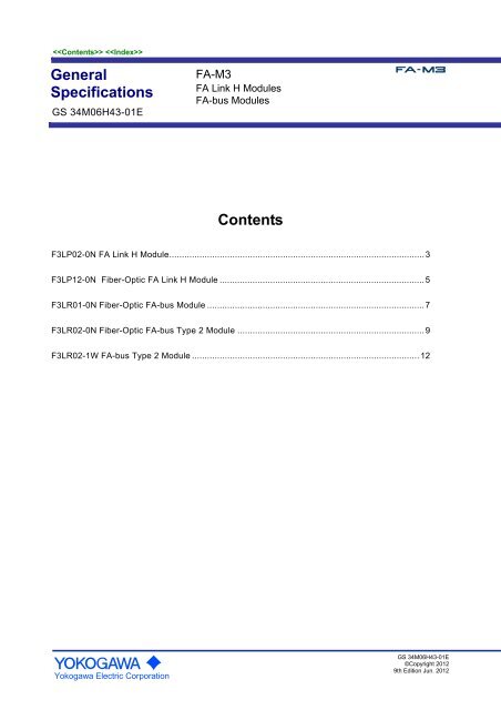
GeneralSpecificationsGS 34M06H43-01E<strong>FA</strong>-M3<strong>FA</strong> <strong>Link</strong> H <strong>Modules</strong><strong>FA</strong>-<strong>bus</strong> <strong>Modules</strong>ContentsF3LP02-0N <strong>FA</strong> <strong>Link</strong> H Module ..................................................................................................... 3F3LP12-0N Fiber-Optic <strong>FA</strong> <strong>Link</strong> H Module ................................................................................. 5F3LR01-0N Fiber-Optic <strong>FA</strong>-<strong>bus</strong> Module ...................................................................................... 7F3LR02-0N Fiber-Optic <strong>FA</strong>-<strong>bus</strong> Type 2 Module .......................................................................... 9F3LR02-1W <strong>FA</strong>-<strong>bus</strong> Type 2 Module .......................................................................................... 12<strong>Yokogawa</strong> Electric CorporationGS 34M06H43-01E©Copyright 20129th Edition Jun. 2012
Blank Page
3GeneralSpecificationsF3LP02-0N<strong>FA</strong> <strong>Link</strong> H ModuleGeneralThe F3LP02-0N <strong>FA</strong> <strong>Link</strong> H Module provides a high-speednetwork that allows information exchange between the<strong>FA</strong>-M3 Range-free Multi-controllers.The F3LP02-0N is an <strong>FA</strong> link H interface module thatprovides a maximum of 32 stations of data link (one moduleis counted as one station).- It allows a maximum of eight modules to be installed in asingle <strong>FA</strong>-M3 main unit, to make up a multi-layer datalink. The module can be accessed only from adesignated CPU.- The number of link points can be specified arbitrarily foreach CPU.- Bus-type communication channels are employed tofacilitate the expansion of modules.- <strong>FA</strong> <strong>Link</strong> H <strong>Modules</strong> can be connected easily using atwo-twisted-pair (4-wire) shielded cable.SpecificationsItemSpecificationNumber of stations 32 max.<strong>Link</strong> relays2048 per module- F3SP05/08 and F3SP21: 2048- F3SP22/25/28/35/53/66 and F3SP71-4S:8192 (non-continuous)- F3SP38/58/59/67 and F3SP76-7S:16,384 (non-continuous)<strong>Link</strong> register2048 per module- F3SP05/08 and F3SP21: 2048- F3SP22/25/28/35/53/66 and F3SP71-4S:8192 (non-continuous)- F3SP38/58/59/67 and F3SP76-7S: 16,384(non-continuous)Maximum. Number oflinks per stationSame as above.<strong>Link</strong> relay and linkregister assignments<strong>Link</strong> relay: on 16-relay basis<strong>Link</strong> register: on per register basisNumber of modules F3SP05/08 and F3SP21: 2 max.F3SP22, F3SP25, F3SP28, F3SP35, F3SP38,F3SP53, F3SP58/59, F3SP66/67,F3SP71-4S and F3SP76-7S:8 max.Transmission speed 125 K, 250 K, 625 K or 1.25 Mbps(switch selectable)Transmission channel type 1-<strong>bus</strong> typeTermination resistance 110 Ω at both ends (specified by a built-in switchwhen the line is terminated)Transmission distance 1 km, 500 m, 250 m or 100 m(depends on transmission speed)Communication system Token-<strong>bus</strong> systemSynchronization Frame synchronizationTransmission format Conforms to HDLC.Modulation andencoding systemNRZI systemError detection CRC-CCITT, timeoutRAS features Error detection through local loopback,hardware self-diagnostics, special relay andregister functionsTransmission media Two-twisted-pair (4-wire) shielded cable(AWG20)Current consumption 470 mAExternal connection 4-point terminal block, M3.5 screwsExternal dimensions 28.9 (W) x 100 (H) x 83.2 (D) mm (Note)Weight120 gSurrounding air Operating :0 to 55°Ctemperature range Storage :-20°C to 75°CSurrounding humidity Operating :10 to 90% RH (non-condensing)rangeStorage :10 to 90% RH (non-condensing)SurroundingatmosphereMust be free of corrosive gases, flammablegases or heavy dust.Note: The given dimensions exclude protrusions (See “ExternalDimensions” for details).Note: F3LP02-0N is not compatible with F3SP71-4N and F3SP76-7N.Components and Functions• Front ViewRDYSNDERRLP02-0NSTATION NO.TERMINATOROFF ONAB11SG2233SHIELD44• Right Side ViewIndicatorsRDY: Lit when the internal circuit isfunctioning normally.SND: Lit when the module is sendingdata normally.ERR: Lit when an error occurs.Station No. switch (STATION No.):Sets a station number (01 to 32).The factory setting is 01.Terminator switch (TERMINATOR):ON : Terminator is enabled.OFF: Terminator disabled.The factory setting is OFF.<strong>FA</strong> link H terminal block(4 terminals, M3.5 screws)ParameterswitchesNote: This figure is drawn with the panel cover removed.FactoryNo. 2No. Parameter OFF ONSwitchsettingOFF ON1 Transmission See table OFFNo.1 OFF 1.25 Mbps 250 Kbps2 speed to the right. OFF ON 625 Kbps 125 KbpsOperationHigh3Normal OFFmodespeed4 (Not used) — — OF<strong>FA</strong>ll Rights Reserved. Copyright © 2012, <strong>Yokogawa</strong> Electric Corporation GS 34M06H43-01E Jun., 2012-00
4System Configuration Example1. Connecting between <strong>FA</strong>-M3 ControllersThe F3LP02-0N can be used to configure a system inwhich communication speed can be as high as 1.25Mbps.<strong>FA</strong>-M3F3LP02-0N<strong>FA</strong> <strong>Link</strong> H module<strong>FA</strong> <strong>Link</strong> H modules(1.25 Mbps max., 1 km max., 32 stations)<strong>FA</strong>-M3 <strong>FA</strong>-M3 <strong>FA</strong>-M32. Connecting between <strong>FA</strong>-M3 Controllers, <strong>FA</strong>500 andµ<strong>FA</strong>20<strong>FA</strong>-M3F3LP02-0N<strong>FA</strong> <strong>Link</strong> H Module<strong>FA</strong>-M3F3LP02-0N <strong>FA</strong> <strong>Link</strong> H ModuleLP01-0N<strong>FA</strong> <strong>Link</strong> Module<strong>FA</strong>500for <strong>FA</strong>500µ<strong>FA</strong>20<strong>FA</strong> link 250 kbps (500 m max., 32 stations)- Set the transmission speed of the <strong>FA</strong> <strong>Link</strong> H moduleto 250 kbps.External Connection DiagramTerminatingresistor<strong>FA</strong> link HmoduleABSGSHIELD<strong>FA</strong> link HmoduleABSGSHIELDMaximum total cable length: S m<strong>FA</strong> link HmoduleABSGSHIELDTerminatingresistor1. The maximum total cable length (S) varies dependingon the transmission speed used.2. The SHIELD terminal of this module is internallyconnected to the FG terminal of the <strong>FA</strong>-M3 powersupply module.3. This module has a built-in terminator. Whenconfiguring the module at the end of the cable, set theterminator switch to ON.CablesUse two-pair (4-wire) shielded cable (impedance 100 Ω )when connecting <strong>FA</strong> <strong>Link</strong> H modules.Recommended cables: KM80-□□□/KM81-□□□ (tobe purchased separately).* For details on KM80-□□□and KM81-□□□, see“<strong>FA</strong>-M3 YHLS Master Module, YHLS Slave Units andYHLS Communication Cables (for implementinghigh-speed remote I/O) (GS 34M06H46-03E).Operating Environment- The table below lists the CPU modules that can beused with this module.CPU ModuleF3SP21, F3SP25 and F3SP35F3SP05/ 08, F3SP22, F3SP28, F3SP38,F3SP53/58/59, F3SP66/67,F3SP71-4S, F3SP76-7SStyle No. and ROM Rev.S1 Rev. 8 or laterNote: For the revision number of a CPU module, see the revision numberlabel on the side panel.- The following table summarizes the requirements forthe Ladder Diagram Support Program M3, which canbe used to set up the communications conditions ofthis module. All versions of the Ladder ProgrammingTool WideField3, WideField2 and WideField can beused with this module.Ladder Diagram SupportRevisionProgram M3SF510-E3Rev. 1.08 or laterModel and Suffix CodesModelSuffixCodeStyleCodeOptionCodeF3LP02 -0N . . . . . . . . . .External Dimensions—Description32 stations max.125 k, 250 k, 625 k or 1.25 Mbps1 km, 500 m, 250 m or 100 m83.2 12.128.92Unit:mm100FB0251.VSDAll Rights Reserved. Copyright © 2012, <strong>Yokogawa</strong> Electric Corporation GS 34M06H43-01E Jun., 2012-00
5GeneralSpecificationsF3LP12-0NFiber-optic <strong>FA</strong> <strong>Link</strong> H ModuleGeneralThe F3LP12-0N Fiber-optic <strong>FA</strong> <strong>Link</strong> H Module is ahigh-speed network that allows information exchangebetween the <strong>FA</strong>-M3 Range-free Multi-controllers.The F3LP12-0N is a Fiber-optic <strong>FA</strong> link H interfacemodule that provides a maximum of 32 stations of datalink (one module is counted as one station).- It allows a maximum of eight modules to be installedin a single <strong>FA</strong>-M3 main unit, to making up amulti-layer data link. The module can only beaccessed from a designated CPU.- The number of link points can be specified arbitrarilyfor each CPU.- It supports daisy-chain configuration using fiber-opticcables.- It does not guarantee normal data link in the entirenetwork if any one station on the network is poweredoff.SpecificationsItemSpecificationNumber of stations 32 max.2048 per module- F3SP05/08 and F3SP21: 2048<strong>Link</strong> relays- F3SP22/25/28/35/53, 66 and F3SP71-4S:8192 (non-continuous)- F3SP38/58/59/67 and F3SP76-7S:16,384(non-continuous)2048 per module- F3SP05/08 and F3SP21: 2048<strong>Link</strong> registers- F3SP22/25/28/35/53/66 and F3SP71-4S:8192 (non-continuous)- F3SP38/58/59/67 and F3SP76-7S: 16,384(non-continuous)Max. number of linksper stationSame as above.<strong>Link</strong> relay and link <strong>Link</strong> relay: on 16-relay basisregister assignments <strong>Link</strong> register: on per register basisF3SP05/08 and F3SP21: 2 max.Number of modulesF3SP22, F3SP25, F3SP28, F3SP35, F3SP38,F3SP53, F3SP58/59, F3SP66/67, F3SP71-4S,F3SP76-7S: 8 max.Transmission speed 1.25 MbpsTransmission channelDaisy chaintypeTransmission Maximum total distance: 10 kmdistanceMaximum distance between stations: 1 kmCommunicationsystemToken ringSynchronization Frame synchronizationTransmission format Conforms to HDLC.Modulation andencoding systemNRZI systemError detection CRC-CCITTRAS featureSelf-diagnosticsTransmission media2-core optical fiber (hard plastic clad quartzfiber-optic H-PCF)Current consumption 495 mAExternal dimensions 28.9 (W) x 100 (H) x 83.2 (D) mmWeight110 gSurrounding air Operating :0 to 55°Ctemperature range Storage :-20°C to 75°CSurrounding humidity Operating :10 to 90% RH (non-condensing)rangeStorage :10 to 90% RH (non-condensing)SurroundingatmosphereMust be free of corrosive gases, flammablegases or heavy dust.Note: F3LP12-0N is not compatible with F3SP71-4N and F3SP76-7N.Components and Functions• Front ViewRDYSNDERRSTATION NO.121234• Right Side ViewIndicatorsRDY: Lit when the internal circuit isfunctioning normally.SND: Lit when the module is sendingdata normally.ERR: Lit when an error occurs.Station No. switch (STATION No.):Sets a station number (01 to 32).The factory setting is 01.Fiber-optic connectorOFF1234ParameterswitchesNote: This figure is drawn with the panel cover removed.No. Parameter OFF ON Factory setting1Intermediate Terminal Intermediatestation station stationOFF2 (Not used) — — OFF3 Operation mode Normal High speed OFF4 (Not used) — — OF<strong>FA</strong>ll Rights Reserved. Copyright © 2012, <strong>Yokogawa</strong> Electric Corporation GS 34M06H43-01E Jun., 2012-00
6Configuration ExampleExternal Dimensions• Daisy-chain configurationUnit: mmF3LP12-0NFiber-optic <strong>FA</strong> <strong>Link</strong> H moduleFiber-optic <strong>FA</strong> <strong>Link</strong> H1. The maximum distance between stations is 1 km andthe maximum total distance is 10 km.2. The attached blank cover must be placed on anyunused port of the terminating station.Operating Environment- There is no restriction on the type of CPU modulesthat can be used with this module.CPU ModuleStyle No. and ROM Rev.F3SP21, F3SP25 and F3SP35S1 Rev. 8 or laterF3SP05, F3SP 08, F3SP22, F3SP28,F3SP38, F3SP53/58/59,F3SP66/67,—F3SP71-4S, F3SP76-7SNote: For the revision number of a CPU module, see the revision numberlabel on the side panel.- The following table summarizes the requirements forthe Ladder Diagram Support Program M3, which canbe used to set up the communications conditions ofthis module. All versions of the Ladder ProgrammingTool WideField3, WideField2 and WideField can beused with this module.Ladder Diagram SupportRevisionProgram M3SF510-E3Rev. 1.08 or laterModel and Suffix CodesModelSuffixCodeStyleCodeOptionCodeF3LP12 -0N . . . . . . . . . .Description32 stations max.Maximum total distance: 10 kmMaximum distance betweenstations: 1km1.25MbpsOptional AccessoriesThe customer should prepare fiber-optic cablessatisfying the requirements listed below when connectingbetween Fiber-optic <strong>FA</strong> <strong>Link</strong> H modules. See Fiber-opticCables (GS34M06C92-01E) for details on fiber-opticcables.• Specifications for Fiber-optic Cable Cores<strong>Yokogawa</strong> CableModel NumberKM60KM60,KM61,KM62,KM65Fiber-optic CableModel No.(Size)DK-HPF200/230 2×CCV-HC-20/07Fiber-optic CabletypeSI type※1SI type※1VendorSWCC Showa Sumitomo ElectricCable SystemIndustriesCore diameter200±5μmClad diameter 230 + 0-10 μmTransmission loss7.0dB/km Max.7dB/km Max.(λ=0.85μm,Ta=25℃) (λ=0.81μm,Ta=25℃)※1:Step-index optical fiber• Specifications for Fiber-optic CableConnectors<strong>Yokogawa</strong> CableModel NumberOptical connectorsModel No.VendorSpecificationsKM60KF-07SWCC ShowaCableSystemsBi-directional,lever lockbonding,polishedKM65CF-2011CF-2071SumitomoElectricIndustriesBi-directional,lever lock,crimping, cutKM60,KM61KM62CF-2001HCF-2071HSumitomoElectricIndustriesBi-directional,lever lockbonding,polishedAll Rights Reserved. Copyright © 2012, <strong>Yokogawa</strong> Electric Corporation GS 34M06H43-01E Jun., 2012-00
7GeneralSpecificationsF3LR01-0NFiber-optic <strong>FA</strong>-<strong>bus</strong> ModuleGeneralThe F3LR01-0N is an interface module for constructing asystem that requires distributed placement of multiplemodules. The user can build up an efficient remote I/Osystem by installing F3LR01-0N modules in the <strong>FA</strong>-M3main- and sub-units and connecting them via afiber-optic <strong>FA</strong>-<strong>bus</strong> (fiber-optic cable).- With the 10-Mbps high-speed communicationscapability of the F3LR01-0N, the user does not haveto worry about the I/O refresh time in ladderprogramming.- All I/O module types and most special module types*can be installed in sub-units and accessed just likemodules installed in the main unit.*:See "Restrictions on System Configuration"- No specific communications setup (environmentsetup) is required.- The optical transmission system makes theF3LR01-0N highly immune to noise.SpecificationsItemTransmission speedTransmission mediaTransmissiondistanceTransmissionconfigurationMaximum number ofsub-units (systems)Specification10 Mbps2-core optical fiber (hard plastic cladquartz fiber-optic H-PCF)Maximum total distance: 200 mMaximum distance between stations: 200 mStar7 (systems)Shutdown I/O contact output on transmissionRAS features channel error, reporting of transmissionchannel error locationCurrent consumption 220 mAExternal dimensions 28.9 (W) x 100 (H) x 83.2 (D) mmWeight100 gSurrounding air Operating :0 to 55°Ctemperature range Storage :-20°C to 75°CSurrounding humidity Operating :10 to 90% RH (non-condensing)rangeStorage :10 to 90% RH (non-condensing)SurroundingatmosphereMust be free of corrosive gases, flammablegases or heavy dust.Note: The maximum number of systems when µ-<strong>bus</strong> master stationmodule are used is 1 system less than the value above for eachµ-<strong>bus</strong> master station.Components and Functions• Front ViewRDYERRLR01-0N1 234REMOTESUB UNITNO.• Right Side ViewIndicatorsRDY: Lit when the internal circuitis functioning normally.ERR: Lit when the module fails todetect an input signal froma port.Unit No. switch (SUB UNIT No.)Sets a unit number (0 to 7).0 : Unit number of the main unit1-7: Unit number of the sub-units8,9: Cannot be used.Fiber-optic connectorOFF1234Condition switches(4-pole DIP switch)No. ON OFFFactorySettingShutdown1output234HoldoutputOFFON*: Valid only for outputmodules installed in a subunit.Note: This figure is drawn with the panel cover removed.All Rights Reserved. Copyright © 2012, <strong>Yokogawa</strong> Electric Corporation GS 34M06H43-01E Jun., 2012-00
8System Configuration Example• Star Configuration<strong>FA</strong>-M3 Unit No. 0Main unit<strong>FA</strong>-M3 <strong>FA</strong>-M3 <strong>FA</strong>-M3Unit No. 1Unit No. 2Unit No. 3Operating EnvironmentThere is no restriction on the type of CPU modules thatcan be used with this module.Model and Suffix CodesModelSuffixCodeStyleCodeOptionCodeF3LR01 -0N . . . . . . . . . .DescriptionMaximum total distance:200 mMaximum distancebetween stations: 200 mSub-units*F3LR01-0N Fiber-optic <strong>FA</strong>-<strong>bus</strong> modulefor <strong>FA</strong>-M3External DimensionsUnit: mm• Daisy-chain + Star Configuration<strong>FA</strong>-M3 Unit No. 0Main unit<strong>FA</strong>-M3 <strong>FA</strong>-M3 <strong>FA</strong>500Unit No. 1Unit No. 2Unit No. 3Sub-units*<strong>FA</strong>-M3<strong>FA</strong>500Unit No. 5*: Maximum number of sub-units: 7Unit No. 4F3LR01-0N Fiber-optic <strong>FA</strong>-<strong>bus</strong> modulefor <strong>FA</strong>-M3LR20-0N Fiber-optic <strong>FA</strong>-<strong>bus</strong> modulefor <strong>FA</strong>500Restrictions on System ConfigurationItemMaximum total distanceNumber of connectablesub-unitsNumber of fiber-optic <strong>FA</strong>-<strong>bus</strong>modules installable in a mainunitNumber of fiber-optic <strong>FA</strong>-<strong>bus</strong>modules installable in asub-unit<strong>Modules</strong> installable in asub-unit200 m7 max.Description7 max.(no restrictions on the installationlocation)1(no restrictions on the installationlocation)All I/O modules, and special modulesexcept F3LP , F3LE01, F3LX0and F3NX01 modules.Optional AccessoriesPrepare fiber-optic cables satisfying the requirementslisted below when connecting Fiber-optic <strong>FA</strong>-<strong>bus</strong>modules for extension. See Fiber-optic Cables(GS 34M06C92-01E) for details on fiber-optic cables.• Specifications for Fiber-optic Cable Cores<strong>Yokogawa</strong> CableModel NumberKM60KM60,KM61,KM62,KM65Fiber-optic CableModel No. (Size)DK-HPF200/230 2×CCV-HC-20/07Fiber-optic CabletypeSI type※1SI type※1VendorSWCC Showa Sumitomo ElectricCable SystemIndustriesCore diameter200±5μmClad diameter 230 + 0-10 μmTransmission loss7.0dB/km Max.7dB/km Max.(λ=0.85μm,Ta=25℃) (λ=0.81μm,Ta=25℃)※1:Step-index optical fiber• Specifications for Fiber-optic Cable Connectors<strong>Yokogawa</strong> CableModel NumberOptical connectorsModel No.VendorSpecificationsKM60KF-07SWCC ShowaCableSystemsBi-directional,lever lockbonding,polishedKM65CF-2011CF-2071SumitomoElectricIndustriesBi-directional,lever lock,crimping, cutKM60,KM61KM62,KM67CF-2001HCF-2071HSumitomoElectricIndustriesBi-directional,lever lockbonding,polishedAll Rights Reserved. Copyright © 2012, <strong>Yokogawa</strong> Electric Corporation GS 34M06H43-01E Jun., 2012-00
9GeneralSpecificationsF3LR02-0NFiber-optic <strong>FA</strong>-<strong>bus</strong> Type 2 ModuleGeneralThe F3LR02-0N is an interface module for constructing asystem that requires distributed placement of multiplemodules. The user can build up an efficient remote I/Osystem by installing F3LR02-0N modules in the <strong>FA</strong>-M3main- and sub-units and connecting them via afiber-optic <strong>FA</strong>-<strong>bus</strong> (fiber-optic cable).- With the 10-Mbps high-speed communicationcapability of the F3LR02-0N, the user does not haveto worry about the I/O refresh time in ladderprogramming.- All I/O module types and most special module types*can be installed in sub-units and accessed just likemodules installed in the main unit.*:See "Restrictions on System Configuration"- No specific communication setup (environmentsetup) is required.- The optical transmission system makes theF3LR02-0N highly immune to noise.- A single sub-unit can be segmented into a maximumof 8 stations.- A 2-port (send/receive) system allows daisy-chainconfiguration.- The loop system is switched into two pairs ofdaisy-chain systems when a disconnection occurs inthe system, thereby improving system reliability.SpecificationsItemTransmission speedTransmission mediaTransmissiondistanceTransmissionconfigurationMaximum number ofsub-stationsMaximum number ofsystemsMaximum number ofsub-stations persystemMaximum totaldistance per systemMaximum distancebetween stationsSpecification10 Mbps2-core optical fiber (hard plastic clad quartzfiber-optic H-PCF)Maximum distance between stations: 500 mMaximum total distance: 1.4 km (3 stations)Star, daisy chain, loop567 (Note)321.4 km (3 stations)500 mShutdown I/O contact output on transmissionRAS features channel error, reporting of transmissionchannel error locationCurrent consumption 460 mAExternal dimensions 28.9 (W) x 100 (H) x 83.2 (D) mmWeight120 gSurrounding air Operating :0 to 55°Ctemperature range Storage :-20°C to 75°CSurrounding humidity Operating :10 to 90% RH (non-condensing)rangeStorage :10 to 90% RH (non-condensing)SurroundingatmosphereMust be free of corrosive gases, flammablegases or heavy dust.Note: The maximum number of systems when µ-<strong>bus</strong> master stationmodule are used is 1 system less than the value above for eachµ-<strong>bus</strong> master station.Components and Functions• Front ViewRDYERR1ERR2LR02-0N REMOTE12SUB UNITNO.LEFT SLOTNO.IndicatorsRDY: Lit when the internal circuitis functioning normally.ERR1, ERR2 : Lit when the module fails todetect an input signal froma port.Unit No. switch (SUB UNIT No.):Sets a unit number (0 to 7).0 : Unit number of the main unit1-7 : Unit number of sub-units8, 9 : Cannot be used.First slot number switch(LEFT SLOT NO.)Used to set the first slot number(hexadecimal) of the base module.Fiber-optic connectorCondition SwitchesNo. Meaning OFF ON Factory setHold/reset1 *1 output oncommunicationerrorHold *2outputShutdownoutputON2 Port used Port 1 Both ports *3 OFFDaisyChannel3chain or LoopOFFconfigurationstar4 Reserved — — OFF*1: Valid only for output modules installed in a sub-unit.*2: Continues operation if transmission channel has been secured andsystem operation is continued.*3: Both port 1 and port 2 are used.Light Power Setup SwitchesDistance between stationsNo. Meaning(Fiber-optic cable length) (m)5 Port 1 OFF ON0 - 200 200 - 300 OFF 300 - 400 ON 400 - 5006 intensity OFF OFF ON ON7 Port 2 OFF ON0 - 200 200 - 300 OFF 300 - 400 ON 400 - 5008 intensity OFF OFF ON ON• Right Side View1 O2 F3 F45 O6 F7 F8Note: This figure is drawn with the panel cover removed.All Rights Reserved. Copyright © 2012, <strong>Yokogawa</strong> Electric Corporation GS 34M06H43-01E Jun., 2012-00
10System Configuration Example• Daisy-chain configuration<strong>FA</strong>-M3main unitF3LR02-0NFiber-optic <strong>FA</strong>-<strong>bus</strong> Type 2moduleFiber-optic <strong>FA</strong>-<strong>bus</strong> 2Substation Configuration- Substation Configuration ExampleThe user can configure two or more sub-stations bysplitting a sub-unit using the fiber-optic <strong>FA</strong>-<strong>bus</strong> type 2. Asub-unit logically consists of 16 slots.A maximum of 7 sub-units can be used with the mainunit.Main unit<strong>FA</strong>-M3<strong>FA</strong>-M3Slot 116Sub-stationSub-station32 stationsmax.Sub-unit 1Sub-unit 2Sub-station Sub-station Sub-station Sub-stationSub-station Sub-station Sub-station Sub-station<strong>FA</strong>-M3Sub-unit 7Sub-station Sub-station Sub-station Sub-stationSub-station• Loop configuration<strong>FA</strong>-M3Sub-station<strong>FA</strong>-M3Sub-station<strong>FA</strong>-M3Sub-station<strong>FA</strong>-M3main unitF3LR02-0NFiber-optic <strong>FA</strong>-<strong>bus</strong> Type 2moduleFiber-optic <strong>FA</strong>-<strong>bus</strong> 2<strong>FA</strong>-M3Sub-station<strong>FA</strong>-M3Sub-station32 stationsmax.Restrictions on System ConfigurationItemNumber of Fiber-optic <strong>FA</strong>-<strong>bus</strong>Type 2 modules installable in amaster stationNumber of Fiber-optic <strong>FA</strong>-<strong>bus</strong>Type 2 modules installable in asub-station<strong>Modules</strong> installable in asub-station15 Max.1DescriptionAll I/O modules, and special modulesexcept F3LP, F3LE01, F3LX0and F3NX01 modules.- Subunit Split PatternsSub-units can be split in several patterns. Select anappropriate pattern according to the configuration of yoursystem.SplitpatternF3BU06F3BU06F3BU04F3BU04F3BU09F3BU04F3BU04Slot No.F3BU06F3BU04F3BU06F3BU04F3BU04F3BU04F3BU04FreeFreeFreeFreeF3BU04 F3BU04 F3BU04 F3BU04F3BU04 Free F3BU04 Free F3BU04 Free F3BU04Numberofsub-stations223348FreeWhen pattern (3) is used, for example, it is possible toconnect together up to 7 sub-units, providing a maximumof 21 stations. A 32-station system (maximumconfigurable system) can be configured by combining 6sets of pattern (5) and 1 set of pattern (6). The number ofI/O modules that can be installed in pattern (6) is 1module per sub-station.All Rights Reserved. Copyright © 2012, <strong>Yokogawa</strong> Electric Corporation GS 34M06H43-01E Jun., 2012-00
11Number of Sub-stations and MaximumTotal Distance (m)MaximumTotal Distance (m)NumberofDaisy-chain LoopSubconfigurationconfiguration stations1 500 1000 17 8802 1000 1500 18 8403 1420 19 8004 1380 20 7605 1340 21 7306 1300 22 6907 1260 23 6508 1230 24 6109 1190 25 57010 1150 26 53011 1110 27 50012 1070 28 46013 1030 29 42014 1000 30 38015 960 31 34016 920 32 300NumberofSubstationsMaximumTotal Distance (m)Daisy-chain・LoopconfigurationDo not lay cables such that the actual fiber-optic cable length exceeds theMaximum total distance, or the distance between two stations exceedsthe maximum distance allowed between stations (500 m).External DimensionsUnit: mmOperating Environment- The following table lists the type of CPU modules thatcan be used with this module.CPU Module Style No. and ROM Rev. *1F3SP21, F3SP25 and F3SP35 S1 Rev. 8 or later *2F3SP05/08, F3SP22, F3SP28, F3SP38,F3SP53/58/59, F3SP66/67, F3SP71/76—F3BP20, F3BP30 and F3FP36 —*1: For the revision number of a CPU module, see the revision numberlabel on the side panel.*2: Supports logging of transmission channel error location.- The following table summarizes the requirements forthe Ladder Diagram Support Program M3, which canbe used to set up the communications conditions ofthis module. All versions of the Ladder ProgrammingTool WideField2 and WideField3 can be used withthis module.Ladder Diagram Support Program M3RevisionSF510-E3Rev. 1.08 or later*: Supports logging of transmission channel error location.- The following table lists the type of base modules thatcan be used with this module.Base ModuleID MarkF3BU04R 01 or laterF3BU05 —F3BU06R 01 or laterF3BU09 —F3BU13 —F3BU16 —Model and Suffix CodesModelSuffixCodeStyleCodeOptionCodeF3LR02 -0N . . . . . . . . . .DescriptionMaximum total distance:1.4 kmMaximum distancebetween stations: 500 mOptional AccessoriesPrepare fiber-optic cables satisfying the requirementslisted below when connecting Fiber-optic <strong>FA</strong>-<strong>bus</strong> Type 2modules for extension. See Fiber-optic Cables(GS 34M06C92-01E) for details on fiber-optic cables.• Specifications for Fiber-optic Cable Cores<strong>Yokogawa</strong>Cable ModelNumberFiber-opticCable ModelNo. (Size)Fiber-opticCable typeVendorCore diameterKM60KM60,KM61,KM62,KM65KM67DK-HPF200/230 2×CCV-HC-20/07 2×CCV-HG-20/08SI type※1 SI type※1 GI type※2SWCC ShowaSumitomo ElectricCable SystemIndustries200±5μmClad diameter 230 + 0-10 μm7.0dB/km Max. 7dB/km Max.Transmission8dB/km Max.(λ=0.85μm, (λ=0.81μm,loss(λ=0.81μm,Ta=25℃) Ta=25℃) Ta=25℃)※1:Step-index optical fiber※2:Graded-index optical fiber• Specifications for Fiber-optic Cable Connectors<strong>Yokogawa</strong> CableModel NumberOptical connectorsModel No.VendorSpecificationsKM60KF-07SWCC ShowaCableSystemsBi-directional,lever lockbonding,polishedKM65CF-2011CF-2071SumitomoElectricIndustriesBi-directional,lever lock,crimping, cutKM60,KM61KM62,KM67CF-2001HCF-2071HSumitomoElectricIndustriesBi-directional,lever lockbonding,polishedAll Rights Reserved. Copyright © 2012, <strong>Yokogawa</strong> Electric Corporation GS 34M06H43-01E Jun., 2012-00
05 12GeneralSpecificationsF3LR02-1W<strong>FA</strong>-<strong>bus</strong> Type 2 ModuleGeneralThe F3LR02-1W is an interface module for constructinga system that requires distributed placement of multiplemodules. The user can build up an efficient remote I/Osystem by installing F3LR02-1W modules in the <strong>FA</strong>-M3main- and sub-units and connecting them via a <strong>FA</strong>-<strong>bus</strong>.- With the 10-Mbps high-speed communicationcapability of the F3LR02-1W, the user does not haveto worry about the I/O refresh time in ladderprogramming.- All I/O module types and most special module types*can be installed in sub-units and accessed just likemodules installed in the main unit.*:See "Restrictions on System Configuration"- Both daisy-chain and loop configuration options aresupported.- The loop system is switched into two pairs ofdaisy-chain systems when a disconnection occurs inthe system.SpecificationsItemSpecificationTransmission speed 10 Mbpstwo-pair (4-wire) shielded cableTransmission media(impedance 100Ω)Maximum total distance:Daisy-chain configuration:70mTransmission distanceLoop configuration:80mMaximum distance between stations: 10 mTransmission configuration Star, daisy chain, loopMaximum number ofsubunits (systems)7 (Note)Shutdown I/O contact output on transmissionRAS featureschannel error, reporting of transmissionchannel error locationMust be installed inside panel enclosure orInstallation locationsystemCurrent consumption 320 mAExternal dimensions 28.9 (W) x 100 (H) x 83.2 (D) mmWeight105 gSurrounding air temperature Operating :0 to 55°CrangeStorage :-20°C to 75°CSurrounding humidity range Operating :10 to 90% RH (non-condensing)SurroundingatmosphereStorage :10 to 90% RH (non-condensing)Must be free of corrosive gases, flammablegases or heavy dust.Note: The maximum number of systems when µ-<strong>bus</strong> master stationmodules are used is 1 system less than the value above for eachµ-<strong>bus</strong> master station.The combined maximum number of systems is 7 when <strong>FA</strong> <strong>bus</strong>-2modules are used with Fiber-optic <strong>FA</strong> <strong>bus</strong>-2 modules andFiber-optic <strong>FA</strong> <strong>bus</strong> modules.Components and Functions• Front ViewRDYERR1ERR2LR02-1W REMOTE01981 2R-R+T-T+23746SHIELDSUB UNITNO.R-R+T-T+• Right Side ViewFrontIndicatorsRDYERR1, ERR2: Lit when the internal circuit isfunctioning normally.: Lit when the module fails todetect an input signal from aport.Unit No. Indicator0 : Unit number of the main unit1-7 : Unit number of sub-unitsCommunication portOFF1234RearThis figure is drawn with thepanel cover removed.Parameter switchesCondition SwitchesSWNo.Meaning OFF ONFactorysetting*11Hold/reset output oncommunication error*2Hold outputShutdownoutputON2 Port used Port 1 Both ports *3 OFF3ChannelconfigurationDaisy chainor starLoop OFF4 Reserved — — OFF*1: Valid only for output modules installed in a sub-unit.*2: Continues operation if transmission channel has been secured andsystem operation is continued.*3: Both port 1 and port 2 are used.All Rights Reserved. Copyright © 2012, <strong>Yokogawa</strong> Electric Corporation GS 34M06H43-01E Jun., 2012-00
13System Configuration Example• Daisy-chain configuration<strong>FA</strong>-M3<strong>FA</strong>-M3Main unitF3LR02-1W<strong>FA</strong>-<strong>bus</strong> Type 2module<strong>FA</strong>-<strong>bus</strong> Type 2<strong>FA</strong>-M3Operating Environment- The following table lists the type of CPU modules thatcan be used with this module.CPU Module Style No. and ROM Rev. *1F3SP21, F3SP25 and F3SP35 S1 Rev. 8 or later *2F3SP05, F3SP08, F3SP22,F3SP28, F3SP38, F3SP53,F3SP58/59, F3SP66/67,F3SP71/76F3BP20, F3BP30 and F3FP36 —*1: For the revision number of a CPU module, see the revision numberlabel on the side panel.*2: Supports logging of transmission channel error location.—SubunitSubunit<strong>FA</strong>-M3• Loop configurationSubunitSubunit<strong>FA</strong>-M3<strong>FA</strong>-M3<strong>FA</strong>-M3<strong>FA</strong>-M3Main unitSubunitSubunitSubunitSubunitSubunit<strong>FA</strong>-M3<strong>FA</strong>-M3F3LR02-1W<strong>FA</strong>-<strong>bus</strong> Type 2module<strong>FA</strong>-<strong>bus</strong> Type 2<strong>FA</strong>-M3<strong>FA</strong>-M37 stationsmax.7 stationsmax.- The following table summarizes the requirements forthe Ladder Diagram Support Program M3 that can beused with the module. All versions of the LadderProgramming Tool WideField3, WideField2 andWideField can be used with this module.Ladder Diagram Support Program M3RevisionSF510-E3 Rev. 1.08 or later *3*3: Supports logging of transmission channel error location.- All versions of the Ladder Programming ToolWideField2 can be used with this module.Model and Suffix CodesModelSuffixCodeStyleCodeOptionCodeF3LR02 -1W . . . . . . . . . .External DimensionsDescriptionMaximum total distance:80 m(Loop configuration)Maximum distancebetween stations: 10 mSubunitRestrictions on System ConfigurationItemDescriptionNumber of <strong>FA</strong>-<strong>bus</strong> Type 2 modules7installable in a main unitNumber of <strong>FA</strong>-<strong>bus</strong> Type 2 modules1installable in a subunitAll I/O modules, and specialmodules except F3LP,<strong>Modules</strong> installable in a subunitF3LE01, F3LX0 and F3NX01modules,CablesUse two-pair (4-wire) shielded cable (impedance 100Ω)when connecting <strong>FA</strong>-<strong>bus</strong> Type 2 modules.Recommended cable: KM80- (tested for noiseimmunity, to be purchased separately)* For details on KM80-, see GS34M6H46-03E.All Rights Reserved. Copyright © 2012, <strong>Yokogawa</strong> Electric Corporation GS 34M06H43-01E Jun., 2012-00


