FA Link H Modules FA-bus Modules - Yokogawa
FA Link H Modules FA-bus Modules - Yokogawa
FA Link H Modules FA-bus Modules - Yokogawa

You also want an ePaper? Increase the reach of your titles
YUMPU automatically turns print PDFs into web optimized ePapers that Google loves.
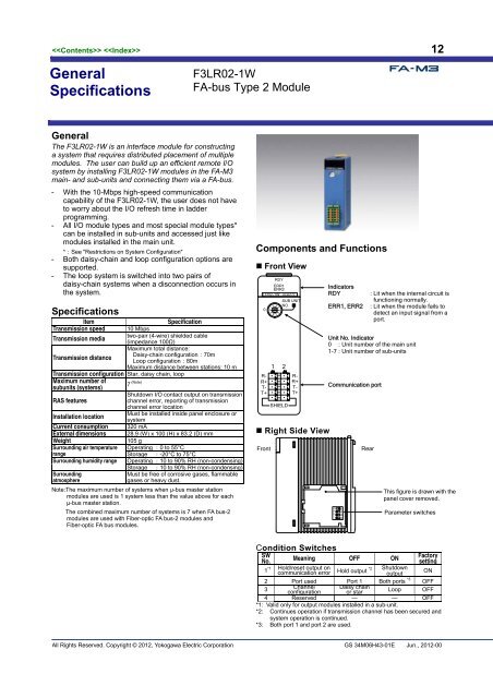
05 12GeneralSpecificationsF3LR02-1W<strong>FA</strong>-<strong>bus</strong> Type 2 ModuleGeneralThe F3LR02-1W is an interface module for constructinga system that requires distributed placement of multiplemodules. The user can build up an efficient remote I/Osystem by installing F3LR02-1W modules in the <strong>FA</strong>-M3main- and sub-units and connecting them via a <strong>FA</strong>-<strong>bus</strong>.- With the 10-Mbps high-speed communicationcapability of the F3LR02-1W, the user does not haveto worry about the I/O refresh time in ladderprogramming.- All I/O module types and most special module types*can be installed in sub-units and accessed just likemodules installed in the main unit.*:See "Restrictions on System Configuration"- Both daisy-chain and loop configuration options aresupported.- The loop system is switched into two pairs ofdaisy-chain systems when a disconnection occurs inthe system.SpecificationsItemSpecificationTransmission speed 10 Mbpstwo-pair (4-wire) shielded cableTransmission media(impedance 100Ω)Maximum total distance:Daisy-chain configuration:70mTransmission distanceLoop configuration:80mMaximum distance between stations: 10 mTransmission configuration Star, daisy chain, loopMaximum number ofsubunits (systems)7 (Note)Shutdown I/O contact output on transmissionRAS featureschannel error, reporting of transmissionchannel error locationMust be installed inside panel enclosure orInstallation locationsystemCurrent consumption 320 mAExternal dimensions 28.9 (W) x 100 (H) x 83.2 (D) mmWeight105 gSurrounding air temperature Operating :0 to 55°CrangeStorage :-20°C to 75°CSurrounding humidity range Operating :10 to 90% RH (non-condensing)SurroundingatmosphereStorage :10 to 90% RH (non-condensing)Must be free of corrosive gases, flammablegases or heavy dust.Note: The maximum number of systems when µ-<strong>bus</strong> master stationmodules are used is 1 system less than the value above for eachµ-<strong>bus</strong> master station.The combined maximum number of systems is 7 when <strong>FA</strong> <strong>bus</strong>-2modules are used with Fiber-optic <strong>FA</strong> <strong>bus</strong>-2 modules andFiber-optic <strong>FA</strong> <strong>bus</strong> modules.Components and Functions• Front ViewRDYERR1ERR2LR02-1W REMOTE01981 2R-R+T-T+23746SHIELDSUB UNITNO.R-R+T-T+• Right Side ViewFrontIndicatorsRDYERR1, ERR2: Lit when the internal circuit isfunctioning normally.: Lit when the module fails todetect an input signal from aport.Unit No. Indicator0 : Unit number of the main unit1-7 : Unit number of sub-unitsCommunication portOFF1234RearThis figure is drawn with thepanel cover removed.Parameter switchesCondition SwitchesSWNo.Meaning OFF ONFactorysetting*11Hold/reset output oncommunication error*2Hold outputShutdownoutputON2 Port used Port 1 Both ports *3 OFF3ChannelconfigurationDaisy chainor starLoop OFF4 Reserved — — OFF*1: Valid only for output modules installed in a sub-unit.*2: Continues operation if transmission channel has been secured andsystem operation is continued.*3: Both port 1 and port 2 are used.All Rights Reserved. Copyright © 2012, <strong>Yokogawa</strong> Electric Corporation GS 34M06H43-01E Jun., 2012-00