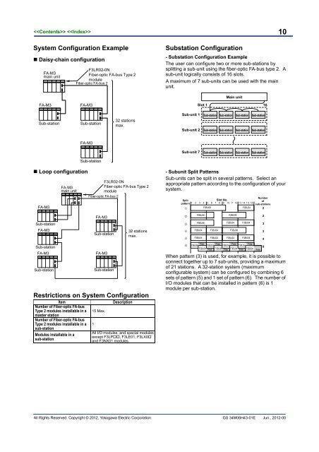
10System Configuration Example• Daisy-chain configuration<strong>FA</strong>-M3main unitF3LR02-0NFiber-optic <strong>FA</strong>-<strong>bus</strong> Type 2moduleFiber-optic <strong>FA</strong>-<strong>bus</strong> 2Substation Configuration- Substation Configuration ExampleThe user can configure two or more sub-stations bysplitting a sub-unit using the fiber-optic <strong>FA</strong>-<strong>bus</strong> type 2. Asub-unit logically consists of 16 slots.A maximum of 7 sub-units can be used with the mainunit.Main unit<strong>FA</strong>-M3<strong>FA</strong>-M3Slot 116Sub-stationSub-station32 stationsmax.Sub-unit 1Sub-unit 2Sub-station Sub-station Sub-station Sub-stationSub-station Sub-station Sub-station Sub-station<strong>FA</strong>-M3Sub-unit 7Sub-station Sub-station Sub-station Sub-stationSub-station• Loop configuration<strong>FA</strong>-M3Sub-station<strong>FA</strong>-M3Sub-station<strong>FA</strong>-M3Sub-station<strong>FA</strong>-M3main unitF3LR02-0NFiber-optic <strong>FA</strong>-<strong>bus</strong> Type 2moduleFiber-optic <strong>FA</strong>-<strong>bus</strong> 2<strong>FA</strong>-M3Sub-station<strong>FA</strong>-M3Sub-station32 stationsmax.Restrictions on System ConfigurationItemNumber of Fiber-optic <strong>FA</strong>-<strong>bus</strong>Type 2 modules installable in amaster stationNumber of Fiber-optic <strong>FA</strong>-<strong>bus</strong>Type 2 modules installable in asub-station<strong>Modules</strong> installable in asub-station15 Max.1DescriptionAll I/O modules, and special modulesexcept F3LP, F3LE01, F3LX0and F3NX01 modules.- Subunit Split PatternsSub-units can be split in several patterns. Select anappropriate pattern according to the configuration of yoursystem.SplitpatternF3BU06F3BU06F3BU04F3BU04F3BU09F3BU04F3BU04Slot No.F3BU06F3BU04F3BU06F3BU04F3BU04F3BU04F3BU04FreeFreeFreeFreeF3BU04 F3BU04 F3BU04 F3BU04F3BU04 Free F3BU04 Free F3BU04 Free F3BU04Numberofsub-stations223348FreeWhen pattern (3) is used, for example, it is possible toconnect together up to 7 sub-units, providing a maximumof 21 stations. A 32-station system (maximumconfigurable system) can be configured by combining 6sets of pattern (5) and 1 set of pattern (6). The number ofI/O modules that can be installed in pattern (6) is 1module per sub-station.All Rights Reserved. Copyright © 2012, <strong>Yokogawa</strong> Electric Corporation GS 34M06H43-01E Jun., 2012-00
11Number of Sub-stations and MaximumTotal Distance (m)MaximumTotal Distance (m)NumberofDaisy-chain LoopSubconfigurationconfiguration stations1 500 1000 17 8802 1000 1500 18 8403 1420 19 8004 1380 20 7605 1340 21 7306 1300 22 6907 1260 23 6508 1230 24 6109 1190 25 57010 1150 26 53011 1110 27 50012 1070 28 46013 1030 29 42014 1000 30 38015 960 31 34016 920 32 300NumberofSubstationsMaximumTotal Distance (m)Daisy-chain・LoopconfigurationDo not lay cables such that the actual fiber-optic cable length exceeds theMaximum total distance, or the distance between two stations exceedsthe maximum distance allowed between stations (500 m).External DimensionsUnit: mmOperating Environment- The following table lists the type of CPU modules thatcan be used with this module.CPU Module Style No. and ROM Rev. *1F3SP21, F3SP25 and F3SP35 S1 Rev. 8 or later *2F3SP05/08, F3SP22, F3SP28, F3SP38,F3SP53/58/59, F3SP66/67, F3SP71/76—F3BP20, F3BP30 and F3FP36 —*1: For the revision number of a CPU module, see the revision numberlabel on the side panel.*2: Supports logging of transmission channel error location.- The following table summarizes the requirements forthe Ladder Diagram Support Program M3, which canbe used to set up the communications conditions ofthis module. All versions of the Ladder ProgrammingTool WideField2 and WideField3 can be used withthis module.Ladder Diagram Support Program M3RevisionSF510-E3Rev. 1.08 or later*: Supports logging of transmission channel error location.- The following table lists the type of base modules thatcan be used with this module.Base ModuleID MarkF3BU04R 01 or laterF3BU05 —F3BU06R 01 or laterF3BU09 —F3BU13 —F3BU16 —Model and Suffix CodesModelSuffixCodeStyleCodeOptionCodeF3LR02 -0N . . . . . . . . . .DescriptionMaximum total distance:1.4 kmMaximum distancebetween stations: 500 mOptional AccessoriesPrepare fiber-optic cables satisfying the requirementslisted below when connecting Fiber-optic <strong>FA</strong>-<strong>bus</strong> Type 2modules for extension. See Fiber-optic Cables(GS 34M06C92-01E) for details on fiber-optic cables.• Specifications for Fiber-optic Cable Cores<strong>Yokogawa</strong>Cable ModelNumberFiber-opticCable ModelNo. (Size)Fiber-opticCable typeVendorCore diameterKM60KM60,KM61,KM62,KM65KM67DK-HPF200/230 2×CCV-HC-20/07 2×CCV-HG-20/08SI type※1 SI type※1 GI type※2SWCC ShowaSumitomo ElectricCable SystemIndustries200±5μmClad diameter 230 + 0-10 μm7.0dB/km Max. 7dB/km Max.Transmission8dB/km Max.(λ=0.85μm, (λ=0.81μm,loss(λ=0.81μm,Ta=25℃) Ta=25℃) Ta=25℃)※1:Step-index optical fiber※2:Graded-index optical fiber• Specifications for Fiber-optic Cable Connectors<strong>Yokogawa</strong> CableModel NumberOptical connectorsModel No.VendorSpecificationsKM60KF-07SWCC ShowaCableSystemsBi-directional,lever lockbonding,polishedKM65CF-2011CF-2071SumitomoElectricIndustriesBi-directional,lever lock,crimping, cutKM60,KM61KM62,KM67CF-2001HCF-2071HSumitomoElectricIndustriesBi-directional,lever lockbonding,polishedAll Rights Reserved. Copyright © 2012, <strong>Yokogawa</strong> Electric Corporation GS 34M06H43-01E Jun., 2012-00