catalogo DE40 rev.01 07 - Chiller
catalogo DE40 rev.01 07 - Chiller
catalogo DE40 rev.01 07 - Chiller

Create successful ePaper yourself
Turn your PDF publications into a flip-book with our unique Google optimized e-Paper software.
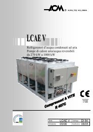
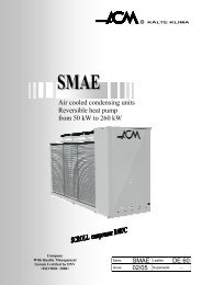
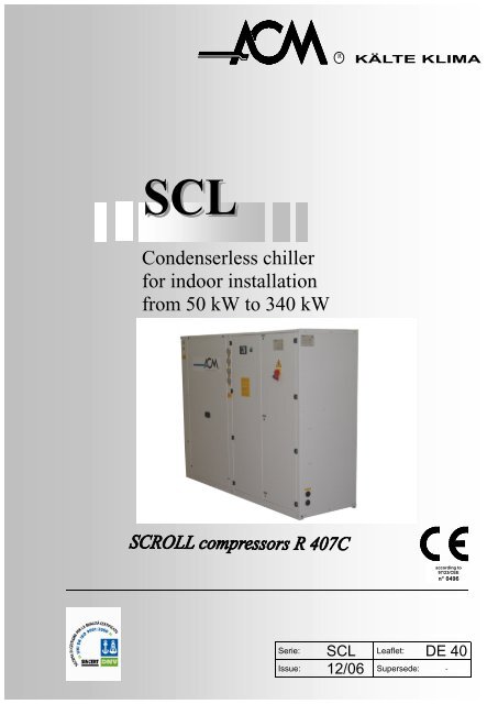
RCondenserless chillerfor indoor installationfrom 50 kW to 340 kWaccording to97/23/CEEn° 0496____________________________________________________________Serie: SCL Leaflet: DE 40Issue: 12/06 Supersede: -
RSCLCondenserless chiller for indoor installationGeneral featuresFRAMESCL/P : self-supporting, galvanized steel frame coatedwith polyester paint.SCL/F e SCL/F…PAC stell frame.COMPRESSORSHermetic “scroll” type with crankcase heater andklixon for overload protection.EVAPORATORSCL/P: braze welded plate to plate type.SCL/F: shell and tube type.Both series are with two independent refrigerant circuitsand one water circuit. The insulation is with a flexibleclosed-cell lining. A differential pressure switch is fittedas a protection which will stop the unit in case there isno water circulation on the plate to plate evaporator.REFRIGERANT CIRCUITEach unit is supplied with one or two independentrefrigerant circuits; each one includes: filter dryer, sightglass, thermostatic expansion valve, service valve.To protect the refrigerant circuit the following devicesare fitted: manual reset high pressure switch, automaticreset low pressure switch, antifreeze thermostat.Besides, only on the size from mod. 111 to 352: manualreset safety pressure switch.ELECTRICAL BOARDIt includes: main circuit automatic breaker switch withdoor locking device, main fuses, compressor contactor ,auxiliary circuits transformer.Microprocessor to automatically control the unit with adisplay to indicate the functions as well as alarmconditions.VersionsDSPartial condensing heat recovery. Each refrigerantcircuit includes a desuperheater insulated and installedin series between the compressors and the condenser.RCSCondensing heat recovery from 70% to 90%. Eachrefrigerant circuit includes: a heat exchanger insulatedand mounted in parallel to the condenser betweencompressor and condenser.RCP100% condensing heat recovery. Each refrigerantcircuit includes: a heat exchanger insulated andmounted in parallel to the condenser and the relevantsolenoid valves.PACAvailable as SCL/F version only. It includes hydraulic kitand storage tank installed on the return line. Thisincludes: insulated storage tank, one or two pumps(one as stand-by), expansion vessel, safety valve, airrelease valve, shut-off valves and, in case of twopumps, non return valve. Relevant electrical circuit. Asan option, pumps with higher ESP are available.LNLow noise version equipped with soundproof materialcovering the compressors.VLNOn request.Options- Power factor condensino capacitors.- Oversized evaporator.- Flowswitch (standard mounted onSCL/F….PAC).- Water pumps with higher ESP.- Compressor suction and discharge shut-offvalves.- Gauges with shut-off valves.- Programmable clock.- Remote control panel.- Evaporator electric heater.- Electric heater for PAC version.- Rubber shock absorbers.- Wooden crate packing.
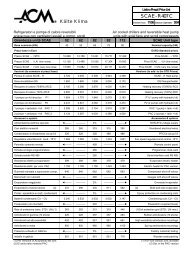
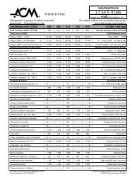
SCL technical dataRSIZE 51 61 81 91 111 131 151 161Cooling capacity (1) kW 48 56 69 84 98 110 136 153Abs. power (2) kW 14.3 16.4 20.4 24.6 28.5 32.4 40.2 44.1COMPRESSORS (scroll)Quantity n° 2Refrigerant circuit n° 1Capacity steps n° 2Refrigerant (4)R 4<strong>07</strong>CEVAPORATOR PLATE-TO-PLATE SCL/PWater flow m 3 /h 8.3 9.6 11.8 14.4 16.8 18.9 23.4 26.3Pressure drop kPa 41 42 42 38 30 38 46 47Water volume l 1,7 2 2,2 2,6 3 3 6,6 6,8Water connections Ø 1½” 1½” 1½” 2½” 2½” 2½” 2½” 2½”Refrigerant (4) kg 1,1 1,1 1,1 2,2 2,7 2,7 2 3,2EVAPORATOR SHELL AND TUBE SCL/FWater flow m 3 /h 8.3 9.6 11.8 14.4 16.8 18.9 23.4 26.3Pressure drop kPa 29 26.5 34.5 27 34 43 43 19.5Water volume l 12 15 16 18.5 29.5 29.5 38 52Water connections PN 10 1½” 2½” 2½” 2½” 3” 3” 3” 3”Refrigerant (4) kg 2,4 2,8 3,2 3,4 4,2 4,2 4,7 5,7CONNECTIONS REFRIGERANT SIDEOutlet (discharge line) Ø 22 22 28 28 35 35 35 42Inlet (liquid line) Ø 18 18 22 22 28 28 28 35UNIT ELECTRICAL DATA (2)Max abs. current A 43 47 57 67 76 85 1<strong>07</strong> 118Max LRC A 148 155 197 235 260 269 330 365Electrical supply V/f/Hz 400/3/50PAC VERSION SHELL AND TUBE EVAPORATORStorage tank water volume l 290 290 470 470 470 470 660 660Water pump nominal power kW 0,9 0,9 1.1 1,1 1,5 1.5 2.2 2.2Water pump nominal current A 2,6 2,6 2,7 2,7 3,5 3,5 5,1 5,1ESP pump kPa 150 160 135 125 125 185 175 150DS VERSION (3)Heating capacity kW 11 12 16 18 21 24 33 37Water flow m 3 /h 0,95 1,0 1,4 1,6 1,8 2,0 2,8 3,2Pressure drop kPa 10 10 15 15 15 15 15 16SOUND PRESSURE at 1 m (2)STD version dB(A) 65 65 68 70 72 73 73 73LN version dB(A) 60 60 63 65 67 68 68 68VLN version dB(A) On request1) Evaporator: water temp. 12 °C / 7 °C; condensing temp. 50 °C (dew point), subcooling 5K2) Compressors only, except pumps.3) Water temperature 40°C / 45°C.4) This data has only to be considered to charge the system as the unit leaves the factory with nitrogen.
RCOOLING CAPACITY AND ABSORBED POWEREVAP. Condensing temperature °CMOD. Tw °C 46 48 50 52 54 56 58out. kWf kWa kWf kWa kWf kWa kWf kWa kWf kWa kWf kWa kWf kWa5 47 13 46 14 45 14,2 43 15 42 16 41 16 40 176 49 13 47 14 46 14,3 45 15 44 16 42 16 41 177 50 13 49 14 48 14,3 47 15 46 16 44 16 43 17518 52 13 51 14 50 14,3 49 15 47 16 46 16 44 179 54 13 53 14 52 14,3 50 15 49 16 48 16 46 1710 56 13 55 14 53 14,3 52 15 51 16 49 16 48 175 55 15 54 16 52 16,3 51 17 49 18 48 19 46 206 57 15 55 16 54 16,4 53 17 51 18 50 19 48 2<strong>07</strong> 58 15 57 16 56 16,4 55 17 53 18 51 19 50 20618 61 15 59 16 58 16,4 57 17 55 18 54 19 52 209 63 15 62 16 60 16,4 59 17 57 18 56 19 54 2010 65 15 64 16 62 16,4 61 17 59 18 58 19 56 205 68 19 66 19 64 20,3 62 21 61 22 59 23 57 246 70 19 68 19 67 20,3 65 21 63 22 61 23 59 247 72 19 71 20 69 20,4 67 21 65 22 63 23 61 24818 75 19 73 20 72 20,4 70 21 68 22 66 23 64 259 78 19 76 20 74 20,4 72 21 71 22 69 23 66 2510 80 19 79 20 77 20,4 75 21 73 22 71 23 69 255 82 22 80 23 78 24,5 76 26 74 27 72 28 69 306 85 22 83 23 81 24,5 79 26 77 27 74 28 72 3<strong>07</strong> 88 22 86 24 84 24,6 82 26 80 27 77 28 74 30918 91 22 89 24 87 24,6 85 26 83 27 80 28 78 309 95 23 92 24 90 24,6 88 26 86 27 83 28 81 3010 98 23 96 24 93 24,6 91 26 89 27 86 28 83 305 96 26 94 27 91 28,4 89 30 86 31 83 33 81 346 99 26 97 27 95 28,4 92 30 90 31 87 33 84 347 102 26 100 27 98 28,5 95 30 93 31 90 33 87 341118 106 26 104 27 102 28,5 99 30 97 31 94 33 91 349 110 26 108 27 105 28,5 103 30 100 31 97 33 94 3410 114 26 112 27 109 28,6 1<strong>07</strong> 30 104 31 101 33 97 345 108 30 105 31 102 32,2 100 34 97 35 94 37 91 396 111 30 109 31 106 32,3 103 34 101 35 97 37 94 397 115 30 112 31 110 32,4 1<strong>07</strong> 34 104 35 101 37 97 391318 119 30 117 31 114 32,4 111 34 109 35 105 37 102 399 124 30 121 31 118 32,4 116 34 113 35 109 37 106 3910 128 30 125 31 122 32,5 120 34 117 36 113 37 109 395 133 37 130 38 126 40,0 123 42 120 44 116 46 112 486 138 37 135 38 131 40,1 128 42 124 44 120 46 116 487 142 37 139 38 136 40,2 132 42 129 44 125 46 120 481518 147 37 144 38 141 40,2 138 42 134 44 130 46 126 489 153 37 150 39 146 40,2 143 42 139 44 135 46 131 4810 158 37 155 39 151 40,3 148 42 144 44 140 46 135 485 150 40 146 42 142 43,9 138 46 135 48 130 50 126 536 155 40 151 42 148 44,0 144 46 140 48 135 51 131 537 160 40 156 42 153 44,1 149 46 145 48 140 51 136 531618 166 40 162 42 159 44,1 155 46 151 48 146 51 141 539 172 40 168 42 164 44,1 161 46 157 48 152 51 147 5310 178 40 174 42 170 44,2 166 46 162 48 157 51 152 53Tw - Evaporator leaving water temperature (delta T 5°C)kWf - Cooling capacitykWa – Absorbed powerCondensing temperature (Dew Point) °C – Subcooling 5K
SCL technical dataRSIZE 181 212 242 262 292 322 352Cooling capacity (1) kW 170 195 216 245 268 305 340Abs. power (2) kW 48 57 64,8 72,6 80,4 88,2 96COMPRESSORS (scroll)Quantity n° 2 4Circuit circuit n° 1 2Capacity steps n° 2 4Refrigerant (4)R 4<strong>07</strong>CEVAPORATOR PLATE TO PLATE SCL/PWater flow m 3 /h 29,3 33,5 37,1 42,1 46 52,4 58,5Pressure drop kPa 47 48 59 53 63 63 65Water volume l 8,2 9,8 9,8 13 13 21 23Water connections Ø 2½” 2½” 2½” 2½” 2½” 2½” 2½”Refrigerant (4) kg 3,5 2x2,5 2x2,5 2x2,9 2x2,9 2x3,4 2x3,9EVAPORATOR SHELL AND TUBE SCL/FWater flow m 3 /h 29,3 33,5 37,1 42,1 46 52,4 58,5Pressure drop kPa 23,5 30,5 31 30,5 36 29,5 35Water volume l 51,4 55 55 105 105 99 99Water connections PN 10 DN 100 DN 100 DN 100 DN 125 DN 125 DN 125 DN 125Refrigerant (4) kg 5,7 2x3,8 2x3,8 2x4,8 2x4,8 2x5,3 2x5,3CONNECTIONS REFRIGERANT SIDEOutlet (discharge line) Ø 42 2*35 2*35 2*35 2*35 2*42 2*42Inlet (liquid line) Ø 35 2*28 2*28 2*28 2*28 2*35 2*35UNIT ELECTRICAL DATA (2)Max abs. current A 129 151 169 191 213 235 257Max LRC A 376 335 353 414 436 482 504Electrical supply V/f/Hz 400/3/50PAC VERSION SHELL AND TUBE EVAPORATORStorage tank water volume l 660 660 660 660 660 660 660Water pump nominal power kW 1,85 2,2 2,2 3 3 3 3Water pump nominal current A 5 5 5 6,5 6,5 6,5 6,5ESP pump kPa 120 128 144 136 125 105 85DS VERSION (3)Heating capacity kW 42 50 55 62 66 79 85Water flow m 3 /h 3,6 4,3 4,7 5,3 5,6 6,8 7,3Pressure drop kPa 16 16 18 18 20 20 20SOUND PRESSURE at 1 m (2)STD Version dB(A) 77 75 76 78 79 79 79LN Version dB(A) 72 70 71 73 74 74 74VLN VersiondB(A)On request1) Evaporator: water temp. 12 °C / 7 °C; condensing temp. 50 °C (dew point), subcooling 5K2) Compressors only, except pumps.3) Water temperature 40°C / 45°C.4) This data has only to be considered to charge the system as the unit leaves the factory with nitrogen.
RCOOLING CAPACITY AND ABSORBED POWEREVAP. Condensing temperature °CMOD. Tw °C 46 48 50 52 54 56 58out. kWf kWa kWf kWa kWf kWa kWf kWa kWf kWa kWf kWa kWf kWa5 167 44 163 46 158 47,8 154 50 150 52 145 55 140 586 172 44 168 46 164 47,9 160 50 156 52 150 55 145 587 177 44 174 46 170 48,0 166 50 161 53 156 55 151 581818 184 44 180 46 176 48,0 172 50 168 53 163 55 157 589 191 44 187 46 183 48,0 179 50 174 53 169 55 164 5810 198 44 193 46 189 48,1 185 50 181 53 175 55 169 585 191 52 186 54 181 56,7 176 59 172 62 166 65 160 686 197 52 193 54 188 56,8 183 60 178 62 173 65 167 687 204 52 199 54 195 57,0 190 60 185 62 179 65 173 682128 211 52 2<strong>07</strong> 54 202 57,0 197 60 192 62 186 65 180 699 219 52 215 55 210 57,0 205 60 200 62 194 66 188 6910 227 52 222 55 217 57,1 212 60 2<strong>07</strong> 63 200 66 194 695 212 59 206 62 201 64,5 195 68 190 71 184 74 178 786 219 59 214 62 208 64,6 203 68 198 71 191 74 185 787 226 59 221 62 216 64,8 210 68 205 71 198 74 191 782428 234 59 229 62 224 64,8 219 68 213 71 206 74 200 789 243 59 238 62 232 64,8 227 68 221 71 214 75 208 7810 251 59 246 62 240 64,9 235 68 229 71 222 75 214 785 240 66 234 69 228 72,2 222 76 216 79 209 83 202 876 248 66 242 69 236 72,4 230 76 224 79 217 83 209 877 256 66 250 69 245 72,6 239 76 233 79 225 83 217 872628 266 66 260 69 254 72,6 248 76 242 79 234 83 226 879 276 67 270 70 263 72,6 257 76 251 79 243 83 236 8710 285 67 279 70 273 72,7 267 76 260 80 252 84 243 875 263 73 256 77 249 80,0 243 84 236 88 228 92 221 966 271 73 265 77 259 80,2 252 84 245 88 237 92 229 967 280 73 274 77 268 80,4 261 84 254 88 246 92 237 962928 291 73 284 77 278 80,4 271 84 265 88 256 92 248 979 302 74 295 77 288 80,4 281 84 275 88 266 92 258 9710 312 74 305 77 298 80,6 292 84 285 88 276 93 266 975 299 80 292 84 284 87,8 276 92 268 96 260 101 251 1066 309 80 302 84 294 87,9 287 92 279 96 270 101 261 1067 318 80 312 84 305 88,2 297 92 289 97 280 101 270 1063228 331 81 324 84 316 88,2 309 92 301 97 292 101 282 1069 343 81 336 84 328 88,2 320 92 313 97 303 101 293 10610 355 81 347 85 339 88,4 332 93 324 97 314 102 303 1065 334 88 325 92 316 95,5 308 100 299 105 290 110 280 1156 344 88 336 92 328 95,7 320 100 311 105 301 110 291 1157 355 88 347 92 340 96,0 331 101 323 105 312 110 301 1153528 369 88 361 92 353 96,0 344 101 336 105 325 110 314 1159 383 88 374 92 366 96,0 357 101 349 105 338 110 327 11610 395 88 387 92 378 96,2 370 101 361 105 350 110 338 116Tw - Evaporator leaving water temperature (delta T 5°C)kWf - Cooling capacitykWa – Absorbed power (Compressor only)Condensing temperature (Dew Point) °C – Subcooling 5K
RRefrigerant circuit SCL1= Compressor2= Condenser3= Evaporator4= Antifreeze probe5= Thermostatic valve6= Dryer7= Shut-off valve, liquid line **8= Shut-off valve, suction line **9= Shut-off valve, discharge line **10= Sight glass11= Service valve12= Low pressure switch13= High pressure switch14= Gauges **15= Probe16= Safety valve (not included)Hydraulic circuit SCL… . . PAC 2 ( PAC 1 )1= Bleed valve2= Expansion vessel3= Gauge4= Shut-off valve5= Pump6= Flowswitch7= Safety valve8= Drain cock9= Indoor exchanger with water tank10= Probe11= Antifreeze probe12= Non return valve(on PAC2-version only)PAC 1 : 1 pump - PAC 2 : 2 pumpsOperating rangeEVAPORATOR INLET WATER TEMPERATUREEVAPORATOR OUTLET WATER TEMPERATURECONDENSING TEMPERATURE (Dew point)Max °C 17Min °C 9Max °C 10Min °C 5Max °C 64Min °C 35
RPRESSURE DROP PLATE-TO-PLATE EVAPORATOR9080618191111/13116118170511516050kPa4030201006 8,5 11 13,5 16 18,5 21 23,5 26 28,5 31 33,5 36WATER FLOW m3/h908<strong>07</strong>0212/242262/2923223526050kPa40302010032 34,5 37 39,5 42 44,5 47 49,5 52 54,5 57 59,5WATER FLOW m3/h
RPRESSURE DROP SHELL AND TUBE EVAPORATOR8<strong>07</strong>051 8161111/131151609150kPa4030161201008 10 12 14 16 18 20 22 24 26 28 30WATER FLOW m3/h6050212/242262/292322/35240181kPa302010028 30 32 34 36 38 40 42 44 46 48 50 52 54 56 58 60 62WATER FLOW m3/hCORRECTION FACTORSEthylene glycol persentage by weight (%) 10 20 30 40 50Freezing point (°C) -3,6 -8,7 -15,3 -23,5 -35,5Cooling capacity 0,986 0,980 0,973 0,966 0,960Abs. power 1,000 0,995 0,990 0,985 0,975Mixture flow 1,023 1,054 1,092 1,140 1,200Pressure drop 1,061 1,114 1,190 1,244 1,310
RFig. AWEIGHT (kg)VERSIONS STD LNMod. 51 61 81 91 111 131 151 161 51 61 81 91 111 131 151 161Fig. A A A A A A A A A A A A A A A AOperation (1) 350 380 395 430 550 600 665 745 375 420 440 500 590 635 690 760Transport 350 380 395 430 550 600 665 745 375 420 440 500 590 635 690 760Vers. “P”Operation (1) 360 395 420 453 588 634 698 778 385 433 465 536 627 678 732 803Transport 360 395 420 453 588 634 698 778 385 433 465 536 627 678 732 803(1) The data has to be added to the evaporator water volume with regards to the selected model.VERSIONS STD LNMod. 182 212 242 262 292 322 352 182 212 242 262 292 322 352Fig. A A A A A A A A A A A A A AOperation (1) 785 910 1035 1060 1130 1170 1210 805 945 1068 1101 1197 1210 1250Transport 785 910 1035 1060 1130 1170 1210 805 945 1068 1101 1197 1210 1250Vers. “P”Operation (1) 810 945 1062 1099 1168 1210 1250 835 975 1098 1136 1238 1250 1290Transport 810 945 1062 1099 1168 1210 1250 835 975 1098 1136 1238 1250 1290(1) The data has to be added to the evaporator water volume with regards to the selected model.NOTE: VLN versions available on request.
RFig. BWEIGHT (kg)VERSIONS STD LNMod. 51 61 81 91 111 131 151 161 51 61 81 91 111 131 151 161Fig. B B B B B B B B B B B B B B B BOperation (1) 510 585 620 700 875 920 1<strong>07</strong>5 1095 530 600 640 720 895 940 1095 1115Transport 510 585 620 700 875 920 1<strong>07</strong>5 1095 530 600 640 720 895 940 1095 1115Vers. “P”Operation (1) 565 645 680 760 930 1040 1125 1185 585 665 700 780 950 1060 1145 1205Transport 545 625 660 740 910 1020 1105 1165 565 645 680 760 930 1040 1125 1185(1) The data has to be added to the evaporator water volume with regards to the selected model.VERSIONS STD LNMod. 182 212 242 262 292 322 352 182 212 242 262 292 322 352Fig. B B B B B B B B B B B B B BOperation (1) 1310 1440 1590 1710 1830 1880 1930 1320 1460 1610 1730 1850 1900 1950Transport 1310 1440 1590 1710 1830 1880 1930 1320 1460 1610 1730 1850 1900 1950Vers. “P”Operation (1) 1390 1520 1670 1790 1910 1960 2020 1410 1540 1690 1810 1930 1980 2040Transport 1350 1480 1630 1750 1870 1920 1980 1370 1500 1650 1770 1890 1940 2000(1) The data has to be added to the evaporator water volume with regards to the selected model.NOTE: VLN versions available on request
Fig. CRWEIGHT (kg)VERSIONS STD LNMod. 51 61 81 91 111 131 151 161 51 61 81 91 111 131 151 161Fig. C C C C C C C C C C C C C C C COperation (1) 790 965 1100 1180 1355 1655 1710 1750 796 970 1105 1185 1360 1675 1720 1770Transport 490 565 600 680 855 900 1055 1<strong>07</strong>5 496 570 605 685 760 906 1064 1<strong>07</strong>5Vers. “P”Operation (1) 805 985 1120 1200 1370 1680 1740 1810 806 990 1125 1205 1380 1695 1740 1830Transport 505 585 620 700 870 980 1<strong>07</strong>5 1125 496 590 625 705 780 926 1084 1145(1) The data has to be added to the evaporator water volume with regards to the selected model.VERSIONI STD LNMod. 182 212 242 262 292 322 352 182 212 242 262 292 322 352Fig. C C C C C C C C C C C C C COperation (1) 1800 2040 2208 2340 2450 2500 2550 1820 2050 2218 2350 2460 2540 2590Transport 1250 1401 1548 1680 1790 1840 1890 1270 1411 1558 1689 1800 1890 1930Vers. “P”Operation (1) 1930 2060 2228 2360 2470 2580 2630 1850 2<strong>07</strong>0 2238 2370 2480 2620 2670Transport 1280 1421 1568 1700 1810 1880 1930 1300 1431 1578 1710 1820 1920 1970(1) The data has to be added to the evaporator water volume with regards to the selected model.Technical data shown in this booklet are not binding. ACM Kälte Klima S.r.l. reserves the right to modify data without pririor notice.ACM Kälte Klima S.r.l. Via dell’Industria, 17 – 35020 ARZERGRANDE (PD) - ITALYTel. +39 049 5800981 Fax +39 049 5800997 e-mail info@acmonline.it - www.acmonline.it