

The 1950's minimitter deluxe transmitter - VMARSmanuals
The 1950's minimitter deluxe transmitter - VMARSmanuals
The 1950's minimitter deluxe transmitter - VMARSmanuals

Create successful ePaper yourself
Turn your PDF publications into a flip-book with our unique Google optimized e-Paper software.
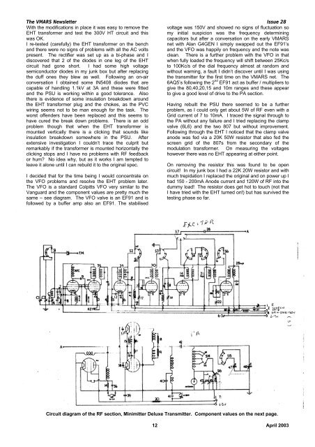
<strong>The</strong> VMARS Newsletter Issue 28With the modifications in place it was easy to remove the voltage was 150V and showed no signs of fluctuation soEHT transformer and test the 300V HT circuit and this my initial suspicion was the frequency determiningwas OK.capacitors but after a conversation on the early VMARSI re-tested (carefully) the EHT transformer on the bench net with Alan G4GEN I simply swapped out the EF91’sand there were no signs of problems with all the AC volts and the VFO was happily on frequency and the note waspresent. <strong>The</strong> rectifier was set up as a bi-phase and I clean. <strong>The</strong>re is a further problem with the VFO in thatdiscovered that 2 of the diodes in one leg of the EHTcircuit had gone short. I had some high voltagesemiconductor diodes in my junk box but after replacingthe duff ones they blew as well. Following an on-airconversation I obtained some IN5408 diodes that arecapable of handling 1.1kV at 3A and these were fittedand the PSU is working within a good tolerance. Alsothere is evidence of some insulation breakdown aroundthe EHT transformer plug and the chokes, as the PVCwiring seems not to be man enough for the task. <strong>The</strong>worst offenders have been replaced and this seems tohave cured the break down problems. <strong>The</strong>re is an oddproblem though that when the EHT transformer ismounted vertically there is a clicking that sounds likeinsulation breakdown somewhere in the PSU. Afterextensive investigation I couldn’t trace the culprit butremarkably if the transformer is mounted horizontally theclicking stops and I have no problems with RF feedbackor hum? No idea why, but as it works I am tempted toleave it alone until I can rebuild it to the original spec.I decided that for the time being I would concentrate onthe VFO problems and resolve the EHT problem later.<strong>The</strong> VFO is a standard Colpitts VFO very similar to theVanguard and the component values are pretty much thesame – see diagram. <strong>The</strong> VFO valve is an EF91 and isfollowed by a buffer amp also an EF91. <strong>The</strong> stabilisedwhen fully loaded the frequency will shift between 25Kc/sto 100Kc/s of the dial frequency almost at random andwithout warning, a fault I didn’t discover until I was usingthe <strong>transmitter</strong> for the first time on the VMARS net. <strong>The</strong>6AQ5’s following the 2 nd EF91 act as buffer / multipliers togive the 80,40,20,15 and 10m ranges and these appearto give a good level of drive to the PA section.Having rebuilt the PSU there seemed to be a furtherproblem, as I could only get about 5W of RF even with aGrid current of 7 to 10mA. I traced the signal through tothe PA without any failure and I tried replacing the clampvalve (6L6) and the two 807 but without improvement.Following through the EHT I noticed that the clamp valveanode was fed via a 20K 50W resistor that also fed thescreen grid of the 807s from the secondary of themodulation transformer. On measuring the voltageshowever there was no EHT appearing at either point.On removing the resistor this was found to be opencircuit! In my junk box I had a 22K 20W resistor and withmuch trepidation I replaced the original and on power up Ihad 150 - 200mA Anode current and 120W of RF into thedummy load! <strong>The</strong> resistor does get hot to touch (not thatI have tried with the EHT turned on!) but has survived thetesting phase so far.Circuit diagram of the RF section, Minimitter Deluxe Transmitter. Component values on the next page.12 April 2003


