Parker NFPA Pneumatic Cylinder - Series MA - Wainbee Limited
Parker NFPA Pneumatic Cylinder - Series MA - Wainbee Limited
Parker NFPA Pneumatic Cylinder - Series MA - Wainbee Limited
- No tags were found...

You also want an ePaper? Increase the reach of your titles
YUMPU automatically turns print PDFs into web optimized ePapers that Google loves.
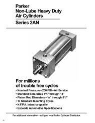
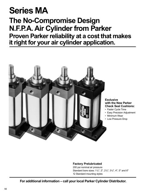
<strong>Series</strong> <strong>MA</strong>The No-Compromise DesignN.F.P.A. Air <strong>Cylinder</strong> from <strong>Parker</strong>Proven <strong>Parker</strong> reliability at a cost that makesit right for your air cylinder application.Exclusivewith the New <strong>Parker</strong>Check Seal Cushions:• Faster Cycle Time• Easy Precision Adjustment• Minimum Wear• Low Pressure DropFactory Prelubricated200 psi nominal air pressureStandard bore sizes: 1 1 /2", 2", 2 1 /2", 3 1 /4", 4", 5" and 6"12 Standard mounting stylesFor additional information – call your local <strong>Parker</strong> <strong>Cylinder</strong> Distributor.56
<strong>Parker</strong> <strong>Series</strong> <strong>MA</strong>N.F.P.A. Industrial Air <strong>Cylinder</strong>s<strong>Parker</strong> <strong>Series</strong> <strong>MA</strong> air cylinders meet or exceed N.F.P.A.<strong>Pneumatic</strong> Standards and except for Tie Rod MountStyles conform to ANSI Standard B93.15-1981 for mountingdimensions of Square Head Industrial Fluid Power<strong>Cylinder</strong>s.For heavy-duty applications see <strong>Parker</strong> <strong>Series</strong> 2A cylinderpage 17.Standard SpecificationsA• Seven bore sizes – 1 1 / 2 " through 6"• Three rod diameters – 5 / 8 ", 1" and 1 3 / 8 "• Twelve mounting styles• Choice of three rod end styles• Cushions at head, cap or both endsAVAILABLE MOUNTINGS• Double rod models in six mounting styles• JIC interchangeable• Temperature Range – 10° F. to 165° F.**See Section C for higher temperature service, operatingfluids, and temperature range.For complete ordering information, see Page 69.For Single Rod Styles, see Pages 60 through 63.Tie Rods Extended Head End Tie Rods Extended Cap End Tie Rods Extended Both Ends Cap Fixed ClevisStyle TB Style TC Style TD Style BB<strong>NFPA</strong> MX2<strong>NFPA</strong> MP1Cap Detachable Clevis Head Rectangular Flange Side Lugs Cap Rectangular FlangeStyle BC Style J Style C Style H<strong>NFPA</strong> MP2 <strong>NFPA</strong> MF1 <strong>NFPA</strong> MS2 <strong>NFPA</strong> MF2Side Tapped Head Trunnion Cap Trunnion Intermediate TrunnionStyle F Style D Style DB Style DD<strong>NFPA</strong> MS4 <strong>NFPA</strong> MT1 <strong>NFPA</strong> MT2 <strong>NFPA</strong> MT4Double Rod <strong>Cylinder</strong>sStyle KTBFor Double Rod Styles, see Page 65.For <strong>Cylinder</strong> Division Plant Locations – See Page II.57
<strong>Parker</strong> <strong>Series</strong> <strong>MA</strong>N.F.P.A. Industrial Air <strong>Cylinder</strong>sThe inside story on the no-compromise designHere’s an inside look at the solid design and construction that makes <strong>Parker</strong><strong>Series</strong> <strong>MA</strong> the high performing, longer-lasting, economical choice for your aircylinder applications.PortsN.P.T.F. ports arestandard.Rugged square steel heads and capsresist shock and provide maximum strengthwithin minimum space. Factory-treated toresist corrosion.Piston rod lipseal/wiper combination iscompletely self-compensating for zeroleakage at all pressures. Keeps pressure in,contamination out.High strength piston rod end stud(125,000 psi minimum yield steel) with rolledthreads for 52% greater strength at thiscritical fatigue point. Choice of male orfemale thread at no extra cost. Anaerobicadhesive is used to permanently lock thestud to the rod.Bolt-on, high strength, rod gland removesscrewdriver-easy on all mountingstyles and bore sizes for fast, on-the-job rodseal replacement if needed.Extra long inboard bearing surfaceinsures lubrication from within the cylinderfor longer life.Factory prelubrication of rod and pistonseal surfaces (rod bearing and cylinderbore surfaces).Tie rods are 100,000 psi minimum yieldsteel with rolled threads for added strength.High strength nuts provide extra margin ofsafety.<strong>Parker</strong>'s New ExclusiveCheck Seal Cushions*For Increased Productivity andMaximum PerformanceThe <strong>Parker</strong> check seal cushion is new and different fromordinary cushion designs. It combines the sealing capabilitiesof a lipseal for efficient capture of air for effective cushioningwith check valve action for quick stroke reversal.The lipseal design also provides “floating cushions” to assurecushion repeatability and long life. At the start of the stroke ineach direction, the check valve design allows full fluid flow topiston face with a minimum pressure drop for maximumpower stroke.Additional benefits of the new check seal cushions areincreased productivity and top performance for faster cycletime, minimum wear, easy adjustment and low pressure drop.*Patent pendingThe basic cushion design is optional and available on eitherthe head end, cap end or both ends without change inenvelope or mounting dimensions. A cushion adjustingneedle is supplied for easy, precise adjustment on all boresizes.At the head end of the cylinder, the check seal is assembledinto a groove in the central bore of the head, with the groovebeing slightly wider and larger in diameter than the checkseal, so that it floats laterally and radially within predeterminedlimits. The check seal has four grooves molded into theface to provide flow passages; the assembly is put togetherwith the lip of the seal facing toward the inside of the cylinder.A cushion sleeve is mounted on the piston rod, so that as therod extends, air ahead of the piston flows freely out the headendport. When the end of the cushion sleeve reaches the lipof the check seal, it seals on the wall of the groove, trappingair for cushioning.As pressure is applied to the head-end port on retraction, theair forces the seal towards the inside of the cylinder. The airFor additional information – call your local <strong>Parker</strong> <strong>Cylinder</strong> Distributor.58
Hard chrome-plated and polished piston rod of100,000 psi yield, high tensile strength steel for reliableperformance and long rod seal life, less friction.<strong>Cylinder</strong> body O-ring seals are pressure-actuatedfor positive sealing. Commercially available and easilyreplaced, if necessary.Unique “check seal” cushions with molded flowpassages combine the benefits of floating cushionswith check valve action, provides effective cushioningand quick stroke reversal for more cycles per hour andhigher production rates. Cushion needle valves makeprecise adjustment quick and easy.ALongest standard cushions in the industry formaximum cushioning capability.Fully dynamic, self-compensating Lipseal ® pistonseals designed for no-leak service at all operatingpressures; easily replaced, if needed, without removingpiston from rod.One-piece, nodular iron piston, positively locked torod – retains lubrication and provides a wide bearingsurface. An anaerobic adhesive is used to permanentlylock and seal the piston to the rod.Piston-to-rod thread diameter increases with roddiameter for added strength and is equal to outer endStyle 4 thread on all rod sizes.Aluminum Alloy cylinder body with corrosion resistantsmooth hard coated bore on 1 1 / 2 " and 2" bores.Chrome Plated Steel Tubing honed to a 15 micro inchfinish on 2 1 / 2 ", 3 1 / 4 ", 4", 5" and 6" bores (cylinderssupplied with reed switches are equipped with aluminumbarrels).then flows around the OD of the seal and through the flutesof the seal washer. Full-flow, quick starts with little or nopressure drop is just one of the major benefits of the design.At the cap end of the cylinder, the check seal is assembledinto a cavity in the face of the cap with four beads molded onthe OD to provide a flow passage. A fluted washer andretaining ring, rather than a groove, and a cushion spearwhich extends from the rear face of the piston complete thecap end assembly. When the rounded, tapered portion of thecushion spear reaches the lip of the seal, the seal seatsagainst the rear wall of the cavity, trapping air for cushioning.The configuration of the check-seal lip, and the controlledshape of the cushion sleeve together prevent the lip fromrolling over or extruding. A check seal used at both endsprovides the benefits of floating cushions with check valveaction for maximum cushion effectiveness and quick strokereversal. This new check-seal design has been tested inmillions of cycles, in the lab and in the field.<strong>Series</strong> <strong>MA</strong> cushions are the longest in the industry and aredesigned for maximum customer benefit.For <strong>Cylinder</strong> Division Plant Locations – See Page II.59
Tie Rod MountingsSingle Rod<strong>Series</strong> <strong>MA</strong><strong>NFPA</strong> Industrial Air <strong>Cylinder</strong>sBasic <strong>Cylinder</strong> Style T (<strong>NFPA</strong> Style MX0)Rod end Style 4 is standardper dimension KK. Styles 8 or9 are optional at no extracharge. A high strength rodend stud is standard on Styles4 and 8 for all rod sizes.For special rod ends such asnonstandard threads, rodextensions, blanks, etc.,specify Style 3 and furnishdesired dimensions for CC,KK, A, WF, LA and LAF.If rod end is not specified,Style 4 will be supplied.E RDRR4AA1E3RCR2RKKD ACROSSFLATSNAStyle 9 Rod End<strong>NFPA</strong> SFACWFRHMM BD ACROSSFLATSCC or KKMMNAACLAFYWFRHBGZB + STROKEP + STROKELF + STROKEEEStyle 4 & 8 Rod End<strong>NFPA</strong> SM & IMJKRod End Dimensions – Styles 9 (<strong>NFPA</strong> SF), 4 (<strong>NFPA</strong> SM) and 8 (<strong>NFPA</strong> IM)ThreadBasic Envelope andMounting DimensionsRod Style Style +.000Rod Dia. 8 4 & 9 -.002 (NPTF)Add StrokeBore No. MM CC KK A B C D LA LAF NA RC RD RH RR V W WF Y AA E EE G J K LF P ZB1 1 / 2 1 5/ 8 1/ 2-20 7 / 16-20 3 / 4 .999 3 / 8 1/ 2 1 3 / 8 1 3 / 4 9/ 16 1 11 / 16 1 5 / 16 3/ 1611/ 64 1/ 4 5/ 8 1 1 15 / 16 2.02 2 3/ 8 1 1 / 2 1 1/ 4 3 5 / 8 2 1 / 4 4 7 / 821 5/ 8 1/ 2-20 7 / 16-20 3 / 4 .999 3 / 8 1/ 2 1 3 / 8 1 3 / 4 9/ 16 1 11 / 16 1 5 / 16 3/ 16 11/ 64 1/ 4 5/ 8 1 1 15 / 16 42.6 2 1 / 2 3/ 8 1 1 / 2 1 5/ 16 3 5 / 8 2 1 / 15 / 1643 1 7/8-14 3/4-16 1 1 /8 1.499 1 /2 7/8 2 1 /8 2 1 /2 15/16 2 3 /16 1 13 /16 3/16 11 /64 1 /2 1 1 3 /8 2 5 /16 5 5 /161 5/ 8 1/ 2-202 1 / 7 / 16-20 3 / 4 .999 3 / 8 1/ 2 1 3 / 8 1 3 / 4 9/ 16 1 11 / 16 1 5 / 16 3/ 1611/ 64 1/ 4 5/ 8 1 1 15 / 16 52 3.1 3 3/ 8 1 1 / 2 1 5/ 16 3 3 / 4 2 3 / 1 / 1683 1 7/ 8-14 3/ 4-16 1 1 / 8 1.499 1 / 2 7/ 8 2 1 / 8 2 1 / 2 15/ 16 2 3 / 16 1 13 / 16 3/ 16 11/ 64 1/ 2 1 1 3 / 8 2 5 / 16 5 7 / 161 1 7/8-14 3/4-16 13 1 / 1 /8 1.499 1 /2 7/8 1 7 /8 2 1 /2 15/16 2 3 /16 1 13 /16 3/16 11 /64 1 /4 3/4 1 3 /8 2 7 /1664 3.9 3 3 / 4 1/ 2 1 3 / 4 1 1 / 4 3/ 8 4 1 / 4 2 5 / 83 1 3 / 8 1 1 / 4-12 1-14 1 5 / 8 1.874 5 / 8 1 1 / 8 2 5 / 8 3 1 / 4 1 5 / 16 2 11 / 16 2 15 / 64 7/ 3213/ 64 3/ 8 1 1 5 / 8 2 11 / 16 6 1 / 41 1 7/ 8-14 3/ 4-16 141 / 8 1.499 1 / 2 7/ 8 1 7 / 8 2 1 / 2 15/ 16 2 3 / 16 1 13 / 16 3/ 16 11/ 64 1/ 4 3/ 4 1 3 / 8 2 7 / 16 64.7 4 1 / 2 1/ 2 1 3 / 4 1 1 / 4 3/ 8 4 1 / 4 2 5 / 83 1 3 /8 1 1 /4-12 1-14 1 5 /8 1.874 5 /8 1 1 /8 2 5 /8 3 1 /4 1 5 /16 2 11 /16 2 15 /64 7/32 13 /64 3 /8 1 1 5 /8 2 11 /16 6 1 /41 1 7/ 8-14 3/ 4-16 151 / 8 1.499 1 / 2 7/ 8 1 7 / 8 2 1 / 215/ 16 2 3 / 16 1 13 / 16 3/ 1611/ 64 1/ 4 3/ 4 1 3 / 8 2 7 / 16 65.8 5 1 / 2 1/ 2 1 3 / 4 1 1 / 4 7/ 16 4 1 / 2 2 7 / 5 / 1683 1 3 / 8 1 1 / 4-12 1-14 1 5 / 8 1.874 5 / 8 1 1 / 8 2 5 / 8 3 1 / 4 1 5 / 16 2 11 / 16 2 15 / 64 7/ 32 13/ 64 3/ 8 1 1 5 / 8 2 11 / 16 6 9 / 16Tie Rod Mounted Styles TB, TC, TDStyle TBStyle TC<strong>NFPA</strong>(MX2)Style TDGDDStyle TB, Tie Rods Extended, is illustrated at right. Style TC, Cap Tie Rods Extended, andStyle TD, Both Ends Tie Rods Extended, can be dimensioned from Style TB drawing.Dimensions for Specific <strong>Series</strong> <strong>MA</strong> Mounting Styles H, J, C, F, BB and BCRod +.000Rod Dia. -.002Bore No. MM BB CB CD CW DD F FB L LR M MR ND NT R SB*1 1 / 2 1 5/ 8 1 3/ 4 .501 1/ 2 1/ 4-28 3/ 8 5/ 16 3/ 4 3/ 4 1/ 2 5/ 8 5/ 16 1/ 4-20 1.43 7/ 161 5/ 821 1 / 8 3/ 4 .501 1/ 2 5/ 16-24 3/ 8 3/ 8 3/ 4 3/ 4 1/ 2 5/ 8 11/ 32 5/ 16-18 1.84 7/ 163 11 5/2 1 8/ 2 1 1 / 8 3/ 4 .501 1/ 2 5/ 16-24 3/ 8 3/ 8 3/ 4 3/ 4 1/ 2 5/ 8 7/ 16 3/ 8-16 2.19 7/ 163 11 13 1 /41 3 /8 1 1 /4 .751 5/8 3/8-24 5/8 7/16 1 1 /4 1 3/4 15/16 1/2 1/2-13 2.76 9/163 1 3 / 81 141 3 / 8 1 1 / 4 .751 5/ 8 3/ 8-24 5/ 8 7/ 16 1 1 / 4 1 3/ 4 15/ 16 5/ 8 1/ 2-13 3.32 9/ 163 1 3 / 81 151 13 / 16 1 1 / 4 .751 5/ 8 1/ 2-20 5/ 8 9/ 16 1 1 / 4 1 3/ 415/ 16 3/ 4 5/ 8-11 4.10 13/ 163 1 3 / 8*Upper surface spotfaced for socket head screws.For additional information – call your local <strong>Parker</strong> <strong>Cylinder</strong> Distributor.BB60
<strong>Series</strong> <strong>MA</strong><strong>NFPA</strong> Industrial Air <strong>Cylinder</strong>sTie Rod MountingsSingle RodFlange Mountings Styles H, JYWFRHZF + STROKEP + STROKELF + STROKEEEUF1UF1D ACROSSFLATSDACROSS FLATSYVZB + STROKEP + STROKELB + STROKEEEMMLAFBKGXF+STROKEJFRFB4 HOLESKK2 4 EE4 2 RRDRR NA3ETF3RCETFFB4 HOLESCWFB MMFCC or KKMMBNACWLA F GJKAStyle H (<strong>NFPA</strong> MF2) Style 9 Rod End J Mount Only Style J (<strong>NFPA</strong> MF1)Side Mountings Styles C, FUSYWFRHZB + STROKEP + STROKELF + STROKEEEE1YWFRHZB + STROKEP + STROKELF + STROKEEEESWSW4RD3RCETS2E.0052 .010STSB4 HOLESSWSWMMBLAF GSW SUXSSS + STROKESUJKSWE 4RDMM3TNRCNT THREAD ND DEEP4 TAPED MTG HOLES2E .0052 .010BLAF GXTSN + STROKEJKStyle C (<strong>NFPA</strong> MS2)Style F (<strong>NFPA</strong> MS4)Pivot Mountings Styles BB, BCYWFRHZC + STROKEP + STROKELF + STROKEEECDPIVOT PINE11ZD + STROKEY P + STROKEWFLB + STROKERH EE CDPIVOT PINMMLAFBKGXC + STROKEJLRLMMR2 4 E42 MMBCW3CBCWStyle BB (<strong>NFPA</strong> MP1)Style BC (<strong>NFPA</strong> MP2)Tie Rods thread into Cap on 1 1 / 2", 2", 2 1 / 2" & 3 1 / 4" bore sizes as shown. Larger sizes have Tie Rod Nuts at both ends.Add StrokeST SU SW TF TN TS UF US LB SN SS XC XD XF XS XT ZC ZF ZD1/ 215/ 16 3/ 8 2 3 / 4 5/ 8 2 3 / 4 3 3 / 8 3 1 / 2 4 2 1 / 4 2 7 / 8 5 3 / 8 5 3 / 4 4 5 / 8 1 3 / 8 1 15 / 16 5 7 / 8 5 6 1 / 451/ 2 15/ 16 3/ 8 3 3 / 8 7/ 8 3 1 / 4 4 1 / 8 4 4 2 1 / 4 2 7 / 3 / 8 5 3 / 4 4 5 / 8 1 3 / 8 1 15 / 16 5 7 / 8 5 6 1 / 485 3 / 4 6 1 / 8 5 1 3 / 4 2 5 / 16 6 1 / 4 5 3 / 8 6 5 / 81/ 215/ 16 3/ 8 3 7 / 8 1 1 / 4 3 3 / 4 4 5 / 8 4 1 / 2 4 1 / 8 2 3 / 8 35 1 / 2 5 7 / 8 4 3 / 4 1 3 / 8 1 15 / 16 6 5 1 / 8 6 3 / 85 7 / 8 6 1 / 4 5 1 / 8 1 3 / 4 2 5 / 16 6 3 / 8 5 1 / 2 6 3 / 43/4 1 1 /4 1/2 4 11 /16 1 1 /2 4 3 /4 5 1 /2 5 3 /4 4 7 /8 2 5 /8 3 1 /46 7 / 8 7 1 / 2 5 5 / 8 1 7 / 8 2 7 / 16 7 5 / 8 6 1 / 4 8 1 / 47 1 / 8 7 3 / 4 5 7 / 8 2 1 / 8 2 11 / 16 7 7 / 8 6 1 / 2 8 1 / 23/ 4 1 1 / 4 1/ 2 5 7 / 16 2 1 / 16 5 1 / 2 6 1 / 4 6 1 / 2 4 7 / 8 2 5 / 8 3 1 / 46 7 / 8 7 1 / 2 5 5 / 8 1 7 / 8 2 7 / 16 7 5 / 8 6 1 / 4 8 1 / 47 1 / 8 7 3 / 4 5 7 / 8 2 1 / 8 2 11 / 16 7 7 / 8 6 1 / 2 8 1 / 21 1 9 / 1611/ 16 6 5 / 8 2 11 / 16 6 7 / 8 7 5 / 8 8 1 / 4 5 1 / 8 2 7 / 8 3 1 / 87 1 / 8 7 3 / 4 5 7 / 8 2 1 / 16 2 7 / 16 7 7 / 8 6 1 / 2 8 1 / 27 3 / 8 8 6 1 / 8 2 5 / 16 2 11 / 16 8 1 / 8 6 3 / 4 8 3 / 43KGXD + STROKELRJ F L MMRFor <strong>Cylinder</strong> Division Plant Locations – See Page II.61
Trunnion Mountings<strong>Series</strong> <strong>MA</strong><strong>NFPA</strong> Industrial Air <strong>Cylinder</strong>sHead Trunnion Mounting Style D (<strong>NFPA</strong> Style MT1)UT1D ACROSSFLATSRHD ACROSSFLATSCC OR KKYWFRHZB + STROKEP+STROKELF+STROKEEEE 4RD.125 R2 TDKKAMM BMMBNANARRTL3RCRETLCWFStyle 9 Rod End(<strong>NFPA</strong> SF)CA XGLAFGStyle 4 & 8 Rod End(<strong>NFPA</strong> SM & IM)JKCap Trunnion Mounting Style DB (<strong>NFPA</strong> Style MT2)E 4RDUT1.125 R2 TDD ACROSSFLATSKKARHMM BD ACROSSFLATSCC OR KKMMYWFRHBZB + STROKEP+STROKELF+STROKEEENANARRTL3RCRETLCWFStyle 9 Rod End(<strong>NFPA</strong> SF)CALAFGXJ + STROKEStyle 4 & 8 Rod End(<strong>NFPA</strong> SM & IM)JKIntermediate Fixed Trunnion MountingStyle DD (<strong>NFPA</strong> Style MT4)RRUVE 4TLRDUM13RCRETMTL.125 R2 TDD ACROSSFLATSKKNAACWFStyle 9 Rod End(<strong>NFPA</strong> SF)For additional information – call your local <strong>Parker</strong> <strong>Cylinder</strong> Distributor.RHMM BD ACROSSFLATSCC OR KKMMNACALAFYWFRHBGXIZB + STROKEP+STROKELF+STROKEEEBDStyle 4 & 8 Rod End(<strong>NFPA</strong> SM & IM)Note: For Rod End Dimensions See Page 60.ThreadBasic Envelope and Mounting DimensionsRodRodDia.Style8Style4 & 9 (NPTF)+.000TD Min.Add StrokeBore No. MM CC KK BD E EE G J K -.001 TL TM UM UT UV XG XI▲ LF P XJ ZB1 1 / 2 1 5/ 8 1/ 2-20 7 / 16-20 1 1 / 4 2 3/ 8 1 1 / 2 1 1/ 4 1.000 1 2 1 / 2 4 1 / 2 4 2 1 / 2 1 3 / 4 3 3 / 16 3 5 / 8 2 1 / 4 4 1 / 8 4 7 / 821 5/ 8 1/ 2-20 7 / 16-201 1 / 2 2 1 / 2 3/ 8 1 1 / 2 1 5/ 16 1.000 1 3 5 4 1 1/ 2 3/ 4 3 5 / 163 5 / 8 2 1 4/ 1 / 8 4 15 / 163 1 7/ 8-14 3/ 4-16 2 1 / 4 8 3 11 / 16 4 1 / 2 5 5 / 162 1 1 5/ 8 1// 2-20 7 / 16-202 1 1 / 2 3 3/ 8 1 1 / 2 1 5/ 16 1.000 1 3 1 / 2 5 1 / 2 5 3 1 1/ 3 / 4 3 5 / 16 2 3 3 / 4 2 3 4/ 1 / 4 5 1 / 163 1 7/ 8-14 3/ 4-16 2 1 / 8 8 3 11 / 16 4 5 / 8 5 7 / 163 1 1 1 7// 8-14 3/ 4-164 2 3 3 / 4 1/ 2 1 3 / 4 1 1 / 4 3/ 8 1.000 1 4 1 / 2 6 1 / 2 5 3 / 4 4 1 2/ 1 / 4 4 3 / 16 4 4 1 / 4 2 5 5 6/3 1 3 / 8 8 1 1 / 4-12 1-14 2 1 / 2 4 7 / 16 5 1 / 4 6 1 / 441311 3 / 87/ 8-141 1 / 4-123/ 4-161-142 4 1 / 2 1/ 2 1 3 / 4 1 1 / 4 3/ 8 1.000 1 5 1 / 4 7 1 / 4 6 1 / 2 52 1 / 42 1 / 24 3 / 164 7 / 164 1 / 4 2 5 / 8 55 1 / 466 1 / 451 1 7/ 8-14 3/ 4-162 5 1 / 2 1/ 2 1 3 / 4 1 1 / 4 7/ 16 1.000 1 6 1 / 4 8 1 / 4 7 1 2/ 2 6/ 4 4 3 / 164 1 / 2 2 7 5/ 1 / 4 6 5 / 163 1 3 / 8 8 1 1 / 4-12 1-14 2 1 / 2 4 7 / 16 5 1 / 2 6 9 / 16▲ Dimension XI to be specified by customerJK62
<strong>Series</strong> <strong>MA</strong>, 6" Bore<strong>NFPA</strong> Industrial Air <strong>Cylinder</strong>sTie Rod and Flange Mountings6" Bore SizeBasic <strong>Cylinder</strong> Style T (<strong>NFPA</strong> Style MX0)Rod end Style 4 is standardper dimension KK. Styles 8 or9 are optional at no extracharge. A high strength rodend stud is standard on Styles4 and 8 for all rod sizes.For special rod ends such asnonstandard threads, rodextensions, blanks, etc.,specify Style 3 and furnishdesired dimensions for CC,KK, A, WF, LA and LAF.If rod end is not specified,Style 4 will be supplied.See Table 3 for rod enddimensions.E 4RDRRAAE13RCR2RKKD ACROSSFLATSNAACWFRHMM BD ACROSSFLATSCC or KKMMNACWFALAFYRHBGZB + STROKEP + STROKELF + STROKEEEJKATie Rod Mounted Styles, TB, TC, TDWFDDBBStyle TB, Tie Rods Extended, is illustrated at right. Style TC, Cap Tie Rods Extended, andStyle TD, Both Ends Tie Rods Extended, can be dimensioned from Style TB drawing.Flange Mountings Styles H, JZF + STROKEZB + STROKERHWFYP + STROKELF + STROKEEEUF1UF1D ACROSSFLATSD ACROSSFLATSYVP + STROKELB + STROKEEECC or KKMMBR24EE 4RD2 RRRKKNABMMMMNABLAFKGXF + STROKEJFFB4 HOLES3ETF3RCETFFB4 HOLESCWFFCWLA FGJKStyle H (<strong>NFPA</strong> MF2) Style 9 Rod End (<strong>NFPA</strong> SF) Style J (<strong>NFPA</strong> MF1)Side Mountings Styles C, FYWFUSRHZB + STROKEP + STROKELF + STROKEEEE1WFYRHZB + STROKEP + STROKELF + STROKEEE1E4RD2E .0052 .010MMB4E RD2E .0052 .010MMBSWSWST3SBLAFRC4 HOLESESWSWTSSWXSStyle C (<strong>NFPA</strong> MS2)GSUSS + STROKESUJKSW3TNRCNT THREAD. ND DEEP4 TAPED MTG. HOLESLAF GXTStyle F (<strong>NFPA</strong> MS4)SN + STROKEJKFor <strong>Cylinder</strong> Division Plant Locations – See Page II.63
Pivot, Cap Trunnion, HeadTrunnion, Intermediate FixedTrunnion Mountings, 6" Bore Size<strong>Series</strong> <strong>MA</strong>, 6" Bore<strong>NFPA</strong> Industrial Air <strong>Cylinder</strong>sPivot Mountings Styles BB, BCYWFRHZC + STROKEP+ STROKELF + STROKEEECDPIVOT PINE11ZD + STROKEY P + STROKEWFLB + STROKERH EE CDPIVOT PINMMB24 E42 MMBMRMRLAFKGXC + STROKEJLRL MCW3CBCW3KGXD + STROKELRJ F L MStyle BB (<strong>NFPA</strong> MP1)Style BC (<strong>NFPA</strong> MP2)Trunnion Mountings Styles D, DBUT1D ACROSSFLATSCC OR KKYWFRHZB + STROKEP + STROKELF+ STROKEEED ACROSSFLATSCC OR KKYWFRHZB + STROKEP + STROKELF + STROKEEE.125 RE 4RD2 TDMMBMMBNANARRTL3RCRETLCA XGLAF GStyle D (<strong>NFPA</strong> MT1)JKCALAFGXJ + STROKEStyle DB (<strong>NFPA</strong> MT2)JKTrunnion Mounting Style DDUM1D ACROSSFLATSCC OR KKYWFRHZB + STROKEP+STROKELF+STROKEEEBD.125 RUVE 4RD2 TDMMBNARRTL3RCRETMStyle DD (<strong>NFPA</strong> MT4)Table 3 Rod End Dimensions—Styles 9 (<strong>NFPA</strong> SF), 4 (<strong>NFPA</strong> SM) and 8 (<strong>NFPA</strong> IM)ThreadRod Style Style +.000Rod Dia. 8 4 & 9 -.002 MIN.Bore No. MM CC KK A B C D LA LAF NA RC RD RH RR V W WF Y6 1 1 3 /8 1 1 /4-12 1-14 1 5 /8 1.874 5/8 1 1 /8 2 1 /2 3 1 /4 1 5 /16 2 11 /16 2 15 /64 7/32 13/64 1/4 7/8 1 5 /8 2 13 /16Table 4 Basic Envelope and Mounting DimensionsRod +.000Rod Dia. -.002 (NPTF)Bore No. MM AA BB BD CB CD CW DD E EE F FB G J K L LR M MR ND NT R SB• ST SU SW6 1 1 3 / 8 6.9 1 13 / 16 2 1 / 2 1 1 / 2 1.001 3 / 4 1/ 2-20 6 1 / 2 3/ 4 3/ 4 9/ 16 2 1 1 / 2 7/ 16 1 1 / 2 1 1 / 4 1 1 3 / 16 7/ 8 3/ 4-10 4.88 13 / 16 1 1 9 / 16 11/ 16Basic Envelope and Mounting Dimensions (cont.)Rod +.000MIN.ADD STROKERod Dia. TD XIBore No. MM -.002 TF TL TM TN TS UF UM US UT UV XG ▲ LB LF P SN SS XC XD XF XJ XS XT ZB ZC ZF6 1 1 3 / 8 1.375 7 5 / 8 1 3 / 8 7 5 / 8 3 1 / 4 7 7 / 8 8 5 / 8 10 3 / 8 9 1 / 4 9 1 / 4 7 2 5 / 8 4 15 / 16 5 3 / 4 5 3 1 / 8 3 1 / 8 3 5 / 8 8 1 / 8 8 7 / 8 6 5 / 8 5 7 / 8 2 5 / 16 2 13 / 16 7 1 / 16 9 1 / 8 7 3 / 8• Upper surface spotfaced for socket head screws. ▲ Dimension XI to be specified by customer.TLFor additional information – call your local <strong>Parker</strong> <strong>Cylinder</strong> Distributor.CALAFGXIJK64
<strong>Series</strong> <strong>MA</strong><strong>NFPA</strong> Industrial Air <strong>Cylinder</strong>sTo dimension double rod cylinders, select the desired mountingstyle and refer to corresponding single rod model on pages 60-Tie Rods Extended<strong>Parker</strong> Style KTTie Rods Extended Head End, Style KTB.Tie Rods Extended Both Ends, Style KTD.1WFYZM + 2 x STROKEP + STROKELG + STROKEEEDouble Rod Models1" to 6" bore sizes64. After obtaining necessary dimensions from that drawing,supplement those with the drawings and tables below.Side Lug Mounting<strong>Parker</strong> Style KC1A42MMB42MMDD3BBG G K3WFXSSSK + STROKESide Tapped Mounting<strong>Parker</strong> Style KFRectangular Flange Mounting<strong>Parker</strong> Style KJ1142MMB42MM3WF3WLE + STROKEXTSNK + STROKEHead Trunnion Mounting<strong>Parker</strong> Style KDIntermediate Fixed Trunnion Mounting<strong>Parker</strong> Style KDD4413132MM2MMWFWFXGXIDouble Rod <strong>Cylinder</strong> DimensionsRod Rod Add Stroke Add 2xBore Dia. No. LG LE SS KSN KStroke ZM1 1 / 2 5/ 8 1 4 1 / 8 4 1 / 2 3 3 / 8 2 1 / 4 6 1 / 85/8 1264 1 / 8 4 1 / 2 3 3 / 8 2 1 / 1 /841 3 6 7 / 82 1 /25/ 8 164 1 /4 4 5 /8 3 1 /2 2 / 43 /81 3 71 173 1 / 4 4 3 / 4 5 3 / 8 3 3 / 4 2 5 / 1 / 281 3 / 8 3 841 174 3 / 4 5 3 / 8 3 3 / 4 2 5 / 1 /281 3 / 8 3 851 175 5 5 /8 3 5 /8 2 / 47 /81 3 /8 3 8 1 /46 1 3 / 8 1 5 1 / 2 6 1 / 4 4 1 / 8 3 1 / 8 8 3 / 4REPLACES DIMENSION LF LB SS SN –ON SINGLE RODMOUNTING STYLEST, TB, TC,C, F, D & DDJ C F ALLOn a double rod cylinder where the two rod ends will be different, besure to state very clearly which rod end is to go at which end of thecylinder.NOTE: For Rod End Dimensions, see pages 60 and 64.For <strong>Cylinder</strong> Division Plant Locations – See Page II.65
Accessories<strong>Cylinder</strong> Accessories<strong>Parker</strong> offers a range of heavy-duty cylinder accessories for convenientmounting of pivot mount cylinders or for use at rod end offixed mount types. All are load capacity rated for use at 4:1 designfactor in tension or compression (pivot pin is rated in shear)<strong>Series</strong> <strong>MA</strong><strong>NFPA</strong> Industrial Air <strong>Cylinder</strong>swhen used on bore sizes recommended in tables below. Selectrod clevises or knuckles by bore and thread size along withmating parts shown. Pivot pin must be ordered as separate item,if needed.MountingPlate1 2Mounting PlatesMounting plates for Style BB and Style BC(clevis mounted) cylinders are offered. Toselect proper part number for your application,refer to Chart below.MountingPlate<strong>Series</strong> “<strong>MA</strong>”Part No.Bore Size69195 1 1 / 2", 2", 2 1 / 2"69196 3 1 / 4", 4", 5"▲85361 6"Dimensions for Rod Clevis and Mating PartsKKBore Rod Thread Rod Eye PivotSize Dia. Size Clevis Brkt. Pin A CB CD CE CL CW DD E ER F FL LR M MR R1 1 / 2 5/ 8 7/ 16-20 50940 69195 68368 3 / 4 3/ 4 1/ 2 1 1 / 2 1 7 / 8 1/ 2 13/ 32 2 1 / 2 1/ 2 3/ 8 1 1 / 8 3/ 4 1/ 2 9/ 16 1.6325/8 7/16-20 50940 69195 68368 3 /4 3/4 1/2 1 1 /2 1 7 /8 1/2 13/32 2 1 /2 1/2 3/8 1 1 /8 3/4 1/2 9/16 1.635094221 3/ 4-16 69196 68369 1 1 / 8 1 1 / 4 3/ / 81332844 2 3 / 2 5 / 8 5/ 8 17/ 32 3 1 / 2 3/ 4 5/ 8 1 7 / 8 1 1 8/ 4 3/ 4 7/ 8 2.551 3/ 4-1650942133284 69196 68369 1 1 / 8 1 1 / 4 3/ 42 1 / 82 3 / 82 5 / 8 5/ 8 17/ 32 3 1 / 2 3/ 4 5/ 8 1 7 / 8 1 1 / 4 3/ 4 7/ 8 2.552 /5/ 8 7/ 16-20 50940 69195 68368 3 / 4 3/ 4 1/ 2 1 1 / 2 1 7 / 8 1/ 2 13/ 32 2 1 / 2 1/ 2 3/ 8 1 1 / 8 3/ 4 1/ 2 9/ 16 1.631 2 5 / 8 5/ 8 17/ 32 3 1 / 2 3/ 4 5/ 8 1 7 / 8 1 1 / 4 3/ 4 7/ 8 2.553 1 /8/ 45094421 3 / 8 1-14 85361▲ 68370 1 5 / 8 1 1 / 2 1 /161332853 1 3 1 / 8 3/ 4 21/ 32 4 1 / 2 1 7/ 8 2 3 / 8 1 1 / 2 1 1 1 / 4 3.25/85094221 3/ 4-16 69196 68369 1 1 / 8 1 1 / 4 3/ / 81332844 2 2 5 / 8 5/ 8 17/ 32 3 1 / 2 3/ 4 5/ 8 1 7 / 8 1 1 / 4 3/ 4 7/ 8 2.554 & 5/ 85094421 3 / 8 1-14 85361▲ 68370 1 5 / 8 1 1 / 2 1 / 161332853 1 / 3 1 / 8 3/ 4 21/ 32 4 1 / 2 1 7/ 8 2 3 / 8 1 1 / 2 1 1 1 8/ 4 3.25509423/ 4-16 133284 69196 68369 1 1 / 8 1 1 / 4 3/ 42 1 /82 3- 1 3 / 8 1-1450944133285 85361▲ 68370 1 5 / 8 1 1 / 2 12 15 / 163 1 / 83 1 / 8 3/ 4 21/ 32 4 1 / 2 1 7/ 8 2 3 / 8 1 1 / 2 1 1 1 / 4 3.25Dimensions for Rod Knuckle and Mating PartsKKBore Rod Thread Clevis PivotSize Dia. Size Knuckle Brkt. Pin A CA CB CD CL CW DD E ER F FL LR M MR R1 1 / 25/ 87/ 16-20 69089 69205 68368 3 / 4 1 1 / 23/ 41/ 2 1 7 / 81/ 213/ 32 3 1 / 223/ 321/ 2 1 1 / 23/ 41/ 25/ 8 2.5525/ 87/ 16-20 69089 69205 68368 3 / 4 1 1 / 23/ 41/ 2 1 7 / 81/ 213/ 32 3 1 / 223/ 321/ 2 1 1 / 23/ 41/ 25/ 8 2.551 3/ 4-16 69091 69206 68369 1 1 / 8 2 1 / 16 1 1 / 43/ 4 2 5 / 85/ 817/ 32 5 1 1 / 165/ 8 1 7 / 8 1 3 / 163/ 429/ 32 3.822 1 /25/8 7/16-20 69089 69205 68368 3 /4 1 1 /2 3/4 1/2 1 7 /8 1/2 13/32 3 1 /2 23/32 1/2 1 1 /2 3/4 1/2 5/8 2.551 3/4-16 69091 69206 68369 1 1 /8 2 1 /16 1 1 /43/4 2 5 /85/817/32 5 1 1 /165/8 1 7 /8 1 3 /163/429/32 3.821 3/ 4-16 69091 69206 68369 13 1 / 1 / 8 2 1 / 16 1 1 / 43/ 4 2 5 / 85/ 817/ 32 5 1 1 / 165/ 8 1 7 / 8 1 3 / 163/ 429/ 32 3.8241 3 / 8 1-14 69093 69207 68370 1 5 / 8 2 13 / 16 1 1 / 2 1 3 1 / 83/ 421/ 32 6 1 / 2 1 7 / 163/ 4 2 1 / 4 1 1 / 2 1 1 1 / 4 4.954 & 51 3/ 4-16 69091 69206 68369 1 1 / 8 2 1 / 16 1 1 / 4 3/ 4 2 5 / 8 5/ 8 17/ 32 5 1 1 / 16 5/ 8 1 7 / 8 1 3 / 16 3/ 4 29/ 32 3.821 3 / 8 1-14 69093 69207 68370 1 5 / 8 2 13 / 16 1 1 / 2 1 3 1 / 8 3/ 4 21/ 32 6 1 / 2 1 7 / 16 3/ 4 2 1 / 4 1 1 / 2 1 1 1 / 4 4.956 1 3 /8 1-14 69093 69207 68370 1 5 /8 2 13 /16 1 1 /2 1 3 1 /8 3/4 21/32 6 1 /2 1 7 /16 3/4 2 1 /4 1 1 /2 1 1 1 /4 4.95▲<strong>Cylinder</strong> accessory dimensions conform to <strong>NFPA</strong> recommended standard <strong>NFPA</strong>/T3.6.8 R1-1984, <strong>NFPA</strong> recommended standard fluid power systems – cylinder –dimensions for accessories for cataloged square head industrial types. <strong>Parker</strong> adopted this standard in April, 1985. Eye brackets or mounting plates shipped before this datemay have different dimensions and will not necessarily interchange with the <strong>NFPA</strong> standard. For dimensional information on older style eye brackets or mounting platesconsult Drawing #144805.For additional information – call your local <strong>Parker</strong> <strong>Cylinder</strong> Distributor.66
NOTESAFor <strong>Cylinder</strong> Division Plant Locations – See Page II.67
How to OrderHow to Order <strong>Series</strong> “<strong>MA</strong>” <strong>Cylinder</strong>sWhen ordering <strong>Series</strong> <strong>MA</strong> cylinders, please review the following:Note: Duplicate cylinders can be ordered by giving the SERIALNUMBER from the nameplate of the original cylinder. Factory recordssupply a quick positive identification.Piston Rods: Specify rod code number based on diameter. Givethread style number for a standard thread or specify dimensions. See“Style 3 Rod End” below.Cushions: If cushions are required specify according to the modelnumber on the next page. If the cylinder is to have a double rod andonly one cushion is required, be sure to specify clearly which end ofthe cylnder is to be cushioned.<strong>Series</strong> <strong>MA</strong><strong>NFPA</strong> Industrial Air <strong>Cylinder</strong>sSpecial Modifications: Additional information is required onorders for cylinders with special modifications. This is besthandled with descriptive notes. For further information, consultfactory.Fluid Medium: <strong>Series</strong> <strong>MA</strong> hydraulic cylinders are equipped withseals for use with lubricated air.Class 1 SealsClass 1 seals are the seals provided as standard in a cylinderassembly unless otherwise specified. For further information on fluidcompatibility or operating limitations of all components, see section C.For the <strong>MA</strong> series cylinders the following make-up Class 1 Seals:Primary Piston Rod Seal – Nitrile with PTFE back-up washersPiston Rod Wiper – NitrilePiston Seals – Nitrile with polymyte back-up washersO-Rings – NitrileCombination MountingsSingle Rod End The first mounting is the one called out on the headend of the cylinder. The second or subsequent mountings are calledout as they appear in the assembly moving away from the rod end.Exception: When tie rod mountings are part of a combination, themodel number should contain an “S” (Special) in the model code anda note in the body of the order clarifying the mounting arrangement.The ”P” is used to define a thrust key and is not considered to be amounting. However, it is located at the primary end.Example: 4.00 CCBB<strong>MA</strong>LTS14AC x 10.000Combination “C” mounting head only. “BB” mounting cap endThis cylinder is also cushioned at both ends.Double Rod End In general, the model number is read left to rightcorresponding to the cylinder as viewed from left to right with theprimary end at rod end #1. See Double Rod Models information pagein this section. For this option the piston rod number, piston rodend, and piston rod threads are to be specified for both ends. Thesimplest are for symmetric cylinders such as: TD, C, E, F, G, andCB mounts. All other mounting styless, the description of the firstrod end will be at the mounting end. In the case of multiplemounts, the description of the first rod end will be at the primarymounting end. For “DD” mounts, the description of the first rodend will be the same location as the “XI” dimension.Example: 4.00 KDD<strong>MA</strong>LT24A/18A x 10.000 XI=8This is a center trunnion mounting cylinder with the XI dimensionmeasured from the code 2 rod side of the cylinder which has thestyle 4 thread. The opposite end code 1 rod with the style 8thread.Style 3 Rod EndA style 3 rod end indicates a special rod end configuration. All specialpiston rod dimensions must have all three: KK; A; W/WF or LA/LAFspecified with the rod fully retracted. A sketch or drawing should besubmitted for rod ends requiring special machining such as snap ringgrooves, keyways, tapers, multiple diameters, etc. It is good designpractice to have this machining done on a diameter at least 0.065inches smaller than the piston rod diameter. This allows the piston rodto have a chamfer preventing rod seal damage during assembly ormaintenance. Standard style 55 rod ends with a longer than standardWG dimension should call out a style 3 rod end and the note:same as 55 except WG=____. A drawing should be submitted forspecial 55 rod ends that have specific tolerances or special radii.Special rod ends that have smaller than standard male threads,larger than standard female threads, or style 55 rod ends withsmaller than standard AF or AE dimensions are to be reviewed byEngineering for proper strength at operating pressure.Service PolicyOn cylinders returned to the factory for repairs, it is standard policy forthe <strong>Cylinder</strong> Division to make such part replacements as will put thecylinder in as good as new condition. Should the condition of the returnedcylinder be such that expenses for repair would exceed the costs of anew one, you will be notified.Address all correspondence and make shipments to, ServiceDepartment at your nearest regional plant listed in the pages of thiscatalog.Certified Dimensions<strong>Parker</strong> <strong>Cylinder</strong> Division guarantees that all cylinders ordered fromthis catalog will be built to dimensions shown. All dimensions arecertified to be correct, and thus it is not necessary to requestcertified drawings.For additional information – call your local <strong>Parker</strong> <strong>Cylinder</strong> Distributor.68
<strong>Series</strong> <strong>MA</strong><strong>NFPA</strong> Industrial Air <strong>Cylinder</strong>sModel Numbers<strong>Series</strong> <strong>MA</strong> Model Numbers – How to Develop Them – How to “Decode” Them<strong>Parker</strong> <strong>Series</strong> <strong>MA</strong> cylinders can be completely and accuratelydescribed by a model number consisting of coded symbols. To developa model number, select only those symbols that represent the cylinderrequired, and place them in the sequence indicated below.Note: Page numbers with a letter prefix, ie: C77, are located insection C of this catalog.Feature Description Page No. SymbolBoreCushion HeadDouble RodMountingStyle<strong>Series</strong>PistonPortsSpecialModificationsPiston RodNumberPiston RodEndPiston RodAlternateThreadsPiston RodThreadsCushion CapStroke•Specify in inchesUsed only if cushion head is requiredUsed only if double rod cylinder isrequiredHead Tie Rods ExtendedCap Tie Rods ExtendedBoth End Tie Rods ExtendedHead Rectangular FlangeCap Rectangular FlangeSide LugSide TappedCap Fixed ClevisCap Detachable ClevisHead TrunnionCap TrunnionIntermediate Fixed TrunnionUsed in all <strong>MA</strong> Model NumbersLipseal ® Piston standard.No need for symbol in model number.NPTF (Dry Seal) Ports are standard.Used only if special modifications arerequired:Oversize PortsPort Position ChangeStop Tube•Stroke AdjusterFluorocarbon SealsFor Single Rod <strong>Cylinder</strong>s, Select onlyone. Check chart on Page C96 forminimum piston rod diameter.Select:Style 4 Small MaleStyle 8 Intermediate MaleStyle 9 Short FemaleStyle 3 Special (Specify)Used only for two times longer thanstandard.UNF StandardBSF (British Fine)MetricUsed only if cushion cap is requiredSpecify in inches*Required for Basic <strong>Cylinder</strong> Model Number •In case of stop tube, call out gross stroke length.Dark Arrows Indicate Basic Minimum Model Number—586560, 6162, 63,64 & 65––C89-91C89-91C89-91C95C93C8360 & 6560, 62, 64, 65C92C9258C93—CKTBTCTDJHCFBBBCDDBDD<strong>MA</strong>––S1348932AWMC–5" C K F – <strong>MA</strong> S 1 4 2 A C x 12"Use symbol S to designate anyspecial modification except piston rod endStyles 4, 8 & 9 are catalog standardsSpecify Style 3 for any special piston rod endExample<strong>Cylinder</strong> serial numbers are factory production record numbers and areassigned to each cylinder, in addition to the model number.Double Rod<strong>Cylinder</strong>sFor double rodcylinders, specify rodnumber and rod endsymbols for bothpiston rods. A typicaldouble rod modelnumber would be:6" KJ-2AU14A/14AX12"AFor <strong>Cylinder</strong> Division Plant Locations – See Page II.69
Switches<strong>Series</strong> <strong>MA</strong><strong>NFPA</strong> Industrial Air <strong>Cylinder</strong>sMagnetically Actuated SwitchesThe <strong>MA</strong> adjustable switch has been designed for use on <strong>Series</strong> <strong>MA</strong> <strong>Pneumatic</strong><strong>Cylinder</strong>s. It is a normally open switch. The compact design of the switch causes aminimum interference with cylinder envelope dimensions. The <strong>MA</strong> switch will sensethe magnetic piston through a non-ferrous cylinder barrel. Several <strong>MA</strong> switches maybe mounted on a single cylinder to control or sequence several functions.The <strong>MA</strong> switch is mounted on a single tie rod with an aluminum extrusion for easyadjustment. Its rugged construction will provide millions of trouble free cycles. It isideally suited as an input to programmable controllers or to activate an industrialrelay.SWITCHOPENSWITCHCLOSED<strong>MA</strong>GNETPISTON SEALReed Switch Assembly<strong>MA</strong>R-2 L074480000Switch SpecificationsSolid State Switch Assembly<strong>MA</strong>S-3 PNP Sourcing L074490000<strong>MA</strong>S-4 NPN Sinking L074500000Switching Logic Normally Open, SPST NPN or PNPSupply Voltage Range 5 to 125 V AC/DC 5 TO 30 VDCMax. Switching Power 10 Watts (Resistive) 5 Watts (Inductive) 6 WattsMax. Switching Current 300 mA (Resistive) 150 mA (Inductive) 200 mA at 24 VDCCircuit Current Consumption — Max 14 mA at 24 VDCShort Circuit Interruption Current — 370 mALeakage Current — 10 µA MaximumResidual Voltage Maximum 3 V 1.5 V Maximum"On" State Voltage Drop 1.7V Maximum See BelowResponse 1000 Hz Maximum 1000 Hz MaximumShock Resistance 30G Non-Repeated Shock 30G Non-Repeated ShockDegree Of Protection IEC IP 67 IEC IP 67Reed Switch Assembly Solid State Switch Assembly<strong>MA</strong>R-2 L074480000 <strong>MA</strong>S-3 PNP Sourcing L074490000<strong>MA</strong>S-4 NPN Sinking L074500000Operating Temperature 14° to 140°F (-10° to 60°C) 14° to 158°F (-10° to 70°C)Storage Temperature -4° to 158°F (-20° to 70°C) -4° to 176°F (-20° to 80°C)LED Indicator Red, Target Present When On Red, Target Present When OnMinimum Current To Light LED 18 mA 1 mALead Wire Lengths 39 Inches, 1 Meter 39 Inches, 1 Meter1 Polarity is restricted to DC operation: (+) to Brown (-) to BlueIf these connections are reversed the contacts will close, but the LED will not light.Note: For switches with connectors and cordsets, see Section C.CircuitsReed Switch (<strong>MA</strong>S-2)Part No. ................ L074480000NOTE: Polarity must be observed forDC operation only.BrownBlueLoadDCorACNPN Sinking Output (<strong>MA</strong>S-4)Part No. ................................................... L074500000Color of Cable ................................................... Black“On” State Voltage Drop ...................... 0.7V MaximumBrownBlackBlueLOAD(+)5 to 30 VDC(-)PNP Sourcing Output (<strong>MA</strong>S-3)Part No. ...................................................L074490000Color of Cable .................................................... Gray“On” State Voltage Drop .................... 0.2V MaximumBrownBlackBlueLOAD(+)5 to 30VDC(-)Circuit for Switching Contact Protection (Inductive Loads)(Required for proper operation 24V DC)Put Diode parallel to loads following polarity as shown below.BrownBlueLoadDD: Diode: select a Diode with the breakdown voltage and current rating according tothe load.Typical Example—100 Volt, 1 Amp DiodeLoad: Relay coil (under 0.5W coil rating) (Recommended for longer life 125 VAC)Caution– Use an ampmeter to test reed switch current. Testing devices such asincandescent light bulbs may subject the reed switch to high in-rush loads.– NOTE: When checking an unpowered reed switch for continuity with adigital ohmmeter the resistance reading will change from infinity to a verylarge resistance (2 M ohm) when the switch is activated. This is due tothe presence of a diode in the reed switch.– Anti-magnetic shielding is recommended for reed switches exposed tohigh external RF or magnetic fields.– The magnetic field strength of the piston magnet is designed to operatewith our switches. Other manufacturers’ switches or sensors may notoperate correctly in conjunction with these magnets.DCPut a resistor and capacitor in parallel with the load. Select the resistor andcapacitor according to the load.Typical Example:Load: Relay coil (under 2W coil rating)R: Resistor 1 KΩ - 5 KΩ, 1/4 WC: Capacitor 0.1 µF, 600 VFor additional information – call your local <strong>Parker</strong> <strong>Cylinder</strong> Distributor.BrownBlueLoad– Current capabilities are relative to operational temperatures.– Use relay coils for reed switch contact protection.– The operation of some 120 VAC PLC's (especially some older Allen-Bradley PLC's) can overload the reed switch. The switch may fail to releaseafter the piston magnet has passed. This problem may be corrected bythe placement of a 700 to 1K OHM resistor between the switch and thePLC input terminal. Consult the manufacturer of the PLC for appropriatecircuit.– Switches with long wire leads (greater than 15 feet) can cause capacitancebuild-up and sticking will result. Attach a resistor in series with the reedswitch (the resistor should be installed as close as possible to the switch).The resistor should be selected such that R (ohms) >E/0.3.RCAC70
<strong>Series</strong> <strong>MA</strong><strong>NFPA</strong> Industrial Air <strong>Cylinder</strong>s<strong>MA</strong> Switch Mounting DataA1.00Switch Mounting DataBMINIMUM ACTIVATION DISTANCEPISTON TRAVEL ATFROM END OF STROKEMIDSTROKEBore A B (SWITCH ON) (±.01) Head Cap1 1 /2 1.90 2.71 .37 .20 .202 2.10 3.25 .37 .20 .202 1 /2* 2.20 3.60 .37 .13 .133 1 /4* 2.70 4.25 .37 .13 .134* 2.90 4.90 .37 .13 .135*† 3.20 5.85 .37 0 06*† 3.82 6.70 .37 0 0NOTE:* To maintain minimumactivation distanceswitch can only bemounted with “LED”against end platebecause of cableinterference on ‘End ofStroke’ applications.† On 5.0" and 6.0" borecylinders, end of strokeactivation will occurwithout the switchphysically touching thehead or cap.AStandard <strong>MA</strong> Switch AssemblyConsists of:1. 0106280032 (2) #8-32 Sh. Cap Screw2. 0108850008 (2) Lockwasher3. 0854530000 (1) Bracket Clamp4. (1) Switch & Bracket Sub-Assembly<strong>MA</strong>R-2 – 0862580000<strong>MA</strong>S-3 – 0862590000<strong>MA</strong>S-4 – 08626000001234How to Order:<strong>MA</strong> switches are not mounted to the cylinder prior to shipment.When ordering a cylinder to accommodate a <strong>MA</strong> switch:1. Derive a proper model number as shown in the table below.2. Place an “S” in the special features column.3. Underneath the model number specify:1) <strong>Cylinder</strong> prepared for <strong>MA</strong> switch.4. As a separate item specify the number of switch assembliesrequired.EXAMPLEPISTONCUSHION PISTON PISTON ROD CUSHIONBORE HEAD DOUBLE MOUNTING SPECIAL ROD ROD ALTERNATE THREAD CAPSIZE END ROD STYLE SERIES FEATURES NO. END THREADS TYPE END STROKE6 C K J <strong>MA</strong> S 1 4 2 A C X12Specify1 1 /2" thru6"Specifyonly ifcushionhead endisrequiredUse onlyif DoubleRod<strong>Cylinder</strong>isrequiredSpecifyMountingStyle: T,TB, TC,TD, J, H,C, F, BB,BC, D, DBor DDSpecify<strong>Series</strong><strong>MA</strong>Specify forcylinderprepared forswitchesand/or othermodificationsSpecifyRodCodeNo.Specify Style4 Small MaleStyle 8IntermediateMaleStyle 9 ShortFemaleStyle 3SpecialSpecify KK, A,LA, LAF, W,WF Dim.Use onlyfor 2xlongerthanstandardrod endthreadSpecify:A = UNFW = BSFM =METRICFor <strong>Cylinder</strong> Division Plant Locations – See Page II.Specifyonly ifCushionCapEnd isrequiredSpecifyininches.ShowSymbol“X” justahead ofstrokelengthExample: To order a 2 1 /2" x 10" <strong>MA</strong> cylinder with <strong>MA</strong> switches to sense the end of stroke at both the head and cap end specify:Item Qty. DescriptionA (1) 2.50 C J <strong>MA</strong>S 14A C x 10.000(1) <strong>Cylinder</strong> prepared for <strong>MA</strong> SwitchB (2) (*) Switch Assemblies* #L074480000 – <strong>MA</strong>R-2#L074490000 – <strong>MA</strong>S-3#L074500000 – <strong>MA</strong>S-471
Magnet Actuated Switches with Quick ConnectCordset with Female Quick ConnectL07486000CL07487000CL07525000CL07526000CL07527000CL07480000CSwitch ConnectorsMagnet Actuated Switches with Quick ConnectMagnet Actuated Switches are available for <strong>Series</strong> SRM, P,2<strong>MA</strong>, MP, and RC cylinders. Refer to the appropriate Catalog Switches with 6" Lead and Quick Connect Male Endinformation for electrical specifications on each switch. Thestandard lead wire length is 39" (1 meter).Switches for the above cylinders are also offered with a 6(six) inch lead with a male quick connect option.Quick ConnectOption(Switch shown withoutmounting brackets)1 BROWN4 BLACK3 BLUE6" leadSwitches are supplied with the bracket to mount the switchto the cylinder. Refer to the switch information for each seriesfor bracket dimensions.<strong>Series</strong> Reed NPN Sinking PNP Sourcing145903000C 146714000C 146715000CL07448000C L07450000C L07449000CSR, P<strong>MA</strong>2<strong>MA</strong>(1 1 /2"-2 1 /2", 5",6")(3 1 /4", 4",8")MP32mm, 40mm50mm, 63mm80mm, 100mmRCL07488000CL07490000CL07528000CL07529000CL07530000CL07481000CL07491000CL07492000CL07531000CL07532000CL07533000CL07482000CCordset with Female Quick Connect(Order Separately)A female connector is available for all switches with the malequick connect option. The male plug will accept a snap-on orthreaded connector. <strong>Cylinder</strong> Division cordset part numbers andother manufacturer’s part numbers are listed below:Snap-OnThreadedManufacturer Version Version<strong>Parker</strong> 086620S005 086620T005Cordset Specifications:Connector: Oil resistant polyurethane body material,PA 6 (Nylon) contact carrier, spacings toVDE 0110 Group C, (150 VAC / DC)Contacts: Gold plated beryllium copper, machinedfrom solid stockCoupling Method: Snap-Lock or chrome plated brass nutCord Construction: Oil resistant black PUR jacket, nonwicking,non-hygroscopic, 300V. Cableend is stripped and tinned.Conductors: Extra high flex stranding, PVC insulationTemperature: -40° to 185°F (-40° to 85°C)Protection: NE<strong>MA</strong> 1, 3, 4, 6P and IEC IP67Cable Length: 6.56 ft (2m) or 16.4 ft (5m)Snap-OnStraight PlugThreadedStraight PlugM8x1fl .3188.1fl .3789.6fl .1774.5 1.110fl .22428.25.71.18130.0fl .1774.51.2632.0.2767.0For additional information – call your local <strong>Parker</strong> <strong>Cylinder</strong> Distributor.72