Refrigerant 410A - HVAC.Amickracing
Refrigerant 410A - HVAC.Amickracing
Refrigerant 410A - HVAC.Amickracing
Create successful ePaper yourself
Turn your PDF publications into a flip-book with our unique Google optimized e-Paper software.
An Alternative to R-22Background<strong>Refrigerant</strong> Characteristics<strong>Refrigerant</strong> SafetySystem Charging Using R-<strong>410A</strong><strong>Refrigerant</strong> <strong>410A</strong> DataR-<strong>410A</strong> Temperature & Pressure ChartRequired Liquid Line TemperatureApplication NotesPUB. # 34-4066-04
REFRIGERANT <strong>410A</strong>BackgroundThe traditional refrigerants, which have been used in central air conditioning systems for thepast fifty years, have been declared to be a threat to the environment. This is due to the presenceof Chlorine in their chemical make-up. As a consequence, the air conditioning industryhas been required to search for a suitable replacement for the most popular of the currentrefrigerants, <strong>Refrigerant</strong> 22.Since there are concerns of efficiency and service use, as well as the environmental issues,the job has not been easy. To locate a replacement and qualify it for use in the products wemanufacture has taken years of work. The refrigerant chosen at this time is <strong>Refrigerant</strong> <strong>410A</strong>.Continuing study will be conducted into other alternates.<strong>Refrigerant</strong> CharacteristicsThe refrigerants developed in the nineteen twenties, using chlorine, such as <strong>Refrigerant</strong> 22,were uniform in their chemical make-up. Such refrigerants are called compounds. Eachmolecule of the refrigerant is like every other molecule. There is no way in the field to separatethe elements of a compound once it has been made. Only the most sophisticated laboratoryequipment can break the building blocks of the refrigerant apart. They contained Hydrogen,Chlorine, Fluorine, and Carbon. These refrigerants were called HCFC’s.The alternative refrigerants are different in the materials used to make them. They are alsodifferent in the manner in which they are made. <strong>Refrigerant</strong>s like <strong>Refrigerant</strong> <strong>410A</strong> are mixturesof chemicals. This means its components are not as tightly bonded together and mayseparate when released from pressure. It is said to be near AZEOTROPIC in its construction.This word means that it is a mixture, not a compound. It is manufactured by combining <strong>Refrigerant</strong>32 and <strong>Refrigerant</strong> 125. Both of these refrigerants are made of Hydrogen, Fluorine, andCarbon and are referred to as HFC’s.The most important reason for using an alternate refrigerant is that it does not contain anyChlorine.Under Federal law, no release of refrigerant is allowed beyond the minimum required to doservice to the products. This “DE MINIMUS” or “least possible” loss must be closely observedduring service to avoid being subject to possible fines and worse. Even the alternative refrigerantscannot be released to atmosphere. The EPA (Environmental Protection Agency) requiresthey must be collected and handled as the existing refrigerants are handled. The issue here isnot Ozone Depletion but the contribution to Global Warming and the waste of a valuable resource.The alternative refrigerant R-<strong>410A</strong> is not a “drop-in” replacement for R-22. Since they usedifferent oils, different drier construction materials and different expansion devices, they requirethe greatest caution in replacement situations. At this time, R-<strong>410A</strong> is intended for use in newequipment.2
The service tools that are used for the alternative refrigerant are not the same as the toolsused for the current refrigerants and this will be explained in this manual. Please read andheed the warnings included in the material in this manual and the manufacturers’ literatureincluded with the products containing this alternative refrigerant.REFRIGERANT SAFETYThe alternative refrigerant, R-<strong>410A</strong>, like R-22 is a safe product. The same precautions mustbe observed when using either one. However, the technician must be aware of several differencesin the handling of R-<strong>410A</strong>.When the cylinders containing <strong>Refrigerant</strong> <strong>410A</strong> are sitting upright, the valve will releaseliquid refrigerant. As you can see in Figure 1, there is a dip tube in the tank reachingto near the bottom of the cylinder. To charge with vapor, turn the cylinder upside down asshown in Figure 2. For cylinders made after 2/99, turn the cylinder upside down as shown inFigure 1A for liquid and upright for vapor as shown in Figure 2A.<strong>Refrigerant</strong> cylinders containing <strong>Refrigerant</strong> <strong>410A</strong> are ROSE colored for identification.<strong>Refrigerant</strong> cylinders should never be stored at 125°F or higher temperatures.Never charge any refrigerant cylinder to greater than 80% of its capacity. This was true for<strong>Refrigerant</strong> 22 and is also true for <strong>Refrigerant</strong> <strong>410A</strong>.<strong>Refrigerant</strong> <strong>410A</strong> boils at -62.9°F. when released to atmosphere. This is twenty degrees colderthan <strong>Refrigerant</strong> 22. The danger of frostbite is much greater on exposed skin. Wear glovesand protect your eyes with safety glasses at all times.This refrigerant, like <strong>Refrigerant</strong> 22, is low in toxicity but it can still be harmful to humans as itdisplaces oxygen. Since it is heavier than air, it will form puddles in low places. Use adequateventilation near equipment that is leaking.<strong>Refrigerant</strong> <strong>410A</strong> is classified as non-flammable. Like <strong>Refrigerant</strong> 22, when mixed with airunder pressure it can ignite. Make sure the system is without pressure before using a torch fora repair.SAFETY AND HANDLINGDOT <strong>Refrigerant</strong> Cylinder InformationStorage and handling limitations are set by the chemical manufacturers to meet Department ofTransportation regulations.R-22 and R-<strong>410A</strong> refrigerant cylinders will have different pressure rating requirements. Theseratings establish the safe pressure ranges that cylinders may be exposed to.The BA400 cylinder is rated for R-<strong>410A</strong>. This cylinder has a service pressure rating of 400PSIG. A BA300 cylinder is rated for R-22. This cylinder has a service pressure rating of 300PSIG. A DOT 39 cylinder is also rated for R-22 and has a service pressure rating of 260 PSIG.3
The Test Pressure of cylinders is defined as 2 times the rated service pressure. Example, aBA400 is rated at 2 times 400 or 800 PSIG. A BA300 is 2 times 300 or 600 Test Pressure. ADOT 39 is 260 times 2 or 520 PSIG Test Pressure.The Department of Transportation requires these cylinders to have a safety device which willrelieve containers contents between 75% and 100% of the test pressure. Minimum relief pressuresettings for BA400 cylinders is 600 PSIG up to a maximum of 800 PSIG. Minimum reliefpressure settings for a BA300 cylinder is 450 PSIG up to a maximum of 600 PSIG. Minimumrelief pressure settings for a DOT 39 is 420 PSIG up to a maximum of 560 PSIG.The Department of Transportation specifies that no product with a saturated pressure at 130°Fbe placed into a cylinder where the refrigerant pressure is greater than 5/4 of the servicepressure. For example, a BA400 cylinder has a service pressure rating of 400 PSIG divided by4 times 5 has a pressure rating of 500 PSIG. R-<strong>410A</strong> at 130 degrees has a pressure of 473PSIG. This pressure is below the 500 PSIG DOT requirement.The BA300 cylinder has service pressure rating of 300 PSIG. 300 PSIG divided by 4 times fivegives us a pressure rating of 375. R-22 has a pressure of 296 PSIG at 130°F making it safe fora BA300 cylinder to contain R-22.The DOT 39 cylinder has a service pressure rating of 260 PSIG. 260 divided by 4 times fiveequals 325 PSIG. This pressure is still above the R-22 pressure of 296 PSIG at 130 degrees.Therefore, R-22 can be stored in a DOT 39 cylinder.OK, so what does all of this mean? Follow the manufacturers recommended storage andhandling information for refrigerants. These requirements include:• Never expose refrigerants to temperatures in excess of 125°F.• Keep refrigerant cylinders out of direct sunlight.• Do not ever overfill your recovery cylinders or try to refill disposable refrigerant cylinders.• Always properly secure refrigerant bottles when transporting.• And most importantly, stay informed by always referring to the latest Material Safety andHandling information as provided by the chemical manufacturers.4
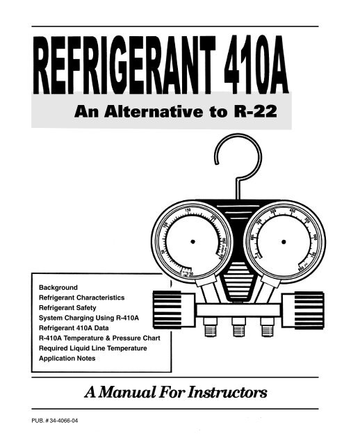
Recovery cylinders used with <strong>Refrigerant</strong> <strong>410A</strong> are not the same cylinders used for<strong>Refrigerant</strong> 22. <strong>Refrigerant</strong> <strong>410A</strong> recovery cylinders are constructed and tested tohigher pressures, 400 PSIG (Pounds to the Square Inch Gauge).Since the vapor pressure of <strong>Refrigerant</strong> <strong>410A</strong> is from 50% to 70% higher than <strong>Refrigerant</strong>22 at the same temperature, service hoses, manifolds and gauges are allconstructed to withstand higher pressures. See Figure 3 for the gauge faces.The oils used with the alternative refrigerant are also different. The oil used withthe HCFC refrigerants such as 22 was mineral oil based. The oil used with<strong>Refrigerant</strong> <strong>410A</strong> is a synthetic oil called POLYOLESTER, abbreviated POE. Thisoil requires special handling. Since it is hygroscopic in nature, (it picks up moisturefrom the air), it must be kept sealed until used. Liquid line driers must be changedwhenever the system is opened for service. A good vacuum cannot adequatelyremove the moisture from the synthetic oil as it did from a mineral oil basedlubricant.The only system additive that may be used is AcidAway. This additive has ONLYbeen approved for <strong>Refrigerant</strong> 22, when used in accordance with themanufacturers’ instructions. All other additives are discouraged and are not recommended.The last caution will seem unusual to the technician. Synthetic oil will attack manymaterials used in roofing. When service is required on equipment mounted on aroof, the surrounding roof must be protected from oil spray or spills. A plasticcovering or tarp must be spread around the work area. This caution must be takenseriously! Wiping up spilled oil will not stop it from causing long term damage toroofing materials.SYSTEM CHARGING USING R-<strong>410A</strong>Charging systems with refrigerants which are classified as AZEOTROPIC, such asR-<strong>410A</strong>, require special technique. The blended refrigerants may tend to separatewhen charging is done with only the vapor. This may lead to FRACTIONATION,when the refrigerants in the blend do not boil off at the exact same temperature.Fortunately, R-<strong>410A</strong> has a well-matched pair of refrigerants. The difference inboiling points is less than a degree. This means that for our purposes therefrigerant does not require you to calculate the temperature difference known asGLIDE. - For all our work, the refrigerant will have a single boiling point for eachpressure.The use of liquid in charging is not new. We have charged the high side of thesystem with liquid for many years. Charging the low side with liquid will require theuse of a special charging metering device. A Chargefaster (CH200) by Watsco or9
its equivalent must be used. This device allows the refrigerant to be taken from the cylinder asliquid but puts it into the system as a vapor. Remember, the refrigerant cylinder will dispenseliquid when it is upright because of the cylinder dip tube on cylinders manufactured before Feb.1999. The cylinder must be inverted, if manufactured after Feb. 1999, to obtain liquid forcharging. To dispense vapor directly, you must turn the cylinder on its top.The subcooling method will be used when an expansion valve (TXV) is installed in the system.In this method of charge adjustment, an accurate reading of the temperature of one of therefrigerant lines is required. The standard service thermometer is not accurate or fast enoughto properly react. An electronic temperature tester, such as an Annie A-8 or equivalent, shouldbe used. The sensing element must be tightly connected to the tubing and insulated from theambient air. The charts for charge adjustment will be found in the equipment and the serviceliterature for the product.While charging the system, allow sufficient time for the system to react to the adjustmentbefore adding or removing charge.REFRIGERANT <strong>410A</strong> DATAThe charts to be used with <strong>Refrigerant</strong> <strong>410A</strong>, (Figure 4), will show the dramatic difference inpressure from the <strong>Refrigerant</strong> 22 pressures.• The typical pressure for 41°F with R-22 is 70 PSIG (Pounds per Square Inch Gauge). WithR-<strong>410A</strong>, it is 120 PSIG. This would be representative of the temperature in the evaporatorof a properly functioning air conditioner.• The pressure for 130°F of R-22 is 300 PSIG. For R-<strong>410A</strong>, it is 475.6 PSIG. This temperaturewould be representative of the conditions in the condenser of an air conditioner on ahot day.If you bring your refrigerant cylinder into the house overnight to check your gauges, with atemperature of 74°F, you will read 130 PSIG for R-22 but 216 PSIG for R-<strong>410A</strong>.At the same temperatures, the pressures for R-<strong>410A</strong> are 50% to 70% higher than theR-22 pressures.The Subcooling chart shown in Figure 5 will help you to make the decisions when chargingunits equipped with thermostatic expansion valves (TXV). Since the valve controlsthe superheat, subcooling must be used to determine the correct charge level.10
R-<strong>410A</strong> Temperature & Pressure ChartTEMP R410 TEMP R410 TEMP R410-60 1.2-55 3.4-50 5.8-45 8.6-40 11.6-35 14.9-30 18.5-25 22.5-20 26.9-15 31.7-10 36.8-5 42.50 48.61 49.92 51.23 52.54 53.85 55.26 56.67 58.08 59.49 60.910 62.311 63.812 65.413 66.914 68.515 70.016 71.717 73.318 75.019 76.620 78.321 80.122 81.823 83.624 85.425 87.326 89.127 91.028 92.929 94.930 96.831 98.832 100.833 102.934 105.035 107.136 109.237 111.438 113.639 115.840 118.041 120.342 122.643 125.044 127.345 129.746 132.247 134.648 137.149 139.650 142.255 155.560 169.665 184.670 200.675 217.480 235.385 254.190 274.195 295.1100 317.2105 340.5110 365.0115 390.7120 417.7125 445.9130 475.6135 506.5140 539.0145 572.8150 608.1155 645.0Pub No. 34-3400-01FIGURE 412
185413
R-<strong>410A</strong> <strong>Refrigerant</strong>It is recommended that charging be done in the liquid phase. When adding liquid refrigerantinto the low side of the system, a charge-metering device is recommended (WATSCO CH200,or equivalent). Allow ample time when adding refrigerant for the system to balance out, toavoid having to recover refrigerant.Existing Halide leak detectors do not work with R-<strong>410A</strong>. Existing acid test kits do not work withR-<strong>410A</strong>. (New kits are being developed.) Existing driers do not work with R-<strong>410A</strong>. Note thatalthough R-<strong>410A</strong> does not deplete the ozone layer, all refrigerants must be recovered.R-<strong>410A</strong> systems use POE oil, which is not compatible with the oils used in R-22 systems. Ifexisting refrigerant lines are to be used with a R-<strong>410A</strong> system (assuming that the line sizes areacceptable), they must be thoroughly blown out with dry nitrogen to remove the old oil. Blowvertical sections from top to bottom.POE oils absorb moisture very quickly. Keep container tightly closed, whenever possible, andexpose the system to the atmosphere as little as possible. POE oils can also damage a roof, ifspilled.Vacuum pumps cannot remove all of the moisture from POE oils. Change the liquid linedrier anytime the system is opened to the atmosphere.Suction line driers are to be left in the system for no more than 72 hours. Use only liquidand suction line driers approved for R-<strong>410A</strong>.Since all current R-<strong>410A</strong> systems are expansion valve systems, the refrigerant charge is to bechecked by the subcooling method.Maximum liquid line pressure drop with R-<strong>410A</strong> systems is 50 PSI (10° subcooling). Recommendedsuction line pressure drop (2°F) is 4.8 PSI (Round up to 5.0).At this time, only matched systems are permitted with R-<strong>410A</strong>. Both indoor and outdoorunits must be changed in a unit replacement.R-<strong>410A</strong> boils at -62.9° at atmospheric pressure, so beware of frostbite!Line set lengths and lift restrictions will be similar to those found in R-22 systems, as long asthe rise is limited to 60 feet and the length is 200 feet or less. Tables on the following pagesshow the line sizes.14
Retrofitting R-22 to R-<strong>410A</strong> Indoor CoilRetrofitting Existing R-22 Systems to R-<strong>410A</strong>We have always recommended installing complete <strong>HVAC</strong> systems regardless of refrigeranttype. The benefits of installing new approved indoor and outdoor split system combinationsare: maximum efficiency, optimum performance, and the best overall system reliability.If you sell a retrofit job and the indoor section (air handler and coil) cannot be changed, someof the previously installed indoor section components may be modified to be compatible withR-<strong>410A</strong>. Refer to Tables 1 and 2 for approved air handlers and coils. Refer to Table 3 forTXV kits.When replacing any <strong>HVAC</strong> system, the existing refrigerant lines must be evaluated to determineif they are properly sized for the new system.Line set lengths and lift restrictions will be similar to those found in R-22 systems. This tableis shown for training only, and must be used only for that purpose. For line sizing, use Pub #32-3009 latest edition. Part of this publication is in the Application Guide section of thispublication.5 Ton 4 Ton 3.5 Ton 3 Ton 2.5 Ton 2 Ton 1.5 Ton 1 TonR-22 1 1/8, 7/8 1 1/8, 7/8 7/8 7/8 3/4 3/4 5/8 5/8R-<strong>410A</strong> 7/8 7/8 3/4 3/4 3/4 5/8 1/2 1/2Liquid Line 3/8 3/8 3/8 3/8 5/16 5/16 1/4 1/4NOTES:This chart illustrates the difference in required size of lines between R-22 and R-<strong>410A</strong>. You willnote the liquid line is unchanged, but the suction line size may change.EvacuationProper evacuation to 500 microns will remove moisture from an R-22/mineral oils system. However,evacuation to 500 microns will not sufficiently remove moisture from a system using POEoils such as used with R-<strong>410A</strong>. To facilitate moisture removal with an R-<strong>410A</strong> systems utilizingPOE oil, the liquid filter drier must be replaced any time the refrigeration system is opened forservice.Liquid Line DrierAll R-<strong>410A</strong> units require a liquid line filter drier. The driers used with R-22 and R-<strong>410A</strong> systemsare different from one another. Specifically, R-<strong>410A</strong> systems use liquid line driers rated for minimumworking pressures of 60OPSIG. Desiccant material must be compatible with POE oils andR-<strong>410A</strong>. Use of the wrong filter drier in R-<strong>410A</strong> systems may result in higher than acceptablemoisture levels.15
Leak DetectionWarning! Never leak test a system with air and R-<strong>410A</strong> under pressure! At pressures above 1atmosphere, just like R-22, mixtures of R-<strong>410A</strong> and air can be combustible. R-<strong>410A</strong> and airshould never be mixed in tanks or supply lines, or be allowed to accumulate in storage tanks.Leak checking can be performed safely with nitrogen or a mixture of R-<strong>410A</strong> and nitrogen. Usea leak detector capable of detecting an HFC gas. Halide leak detectors will not work with R-<strong>410A</strong> systems.Commercially AvailableSolders and Brazing MaterialsDesignationCompositionTemperatureMeltingFlowTIN-LEAD SOLDERSFifty-FiftySixty-FortyEutecticStay-BriteStay-Brite No.850% lead, 50% tin60% lead, 40% tin37% lead, 63% tin——360OF360OF360OF430OF415O F459OF360OF400OF535OFTIN-ANTIMONY SOLDERSNinety-five-Five— 450O F 465O FOMaterialsabove having melting points below 700 F should not be used for refrigerant connections.Easy-Flo (45)Mueller (122)Safety Silv No. 1200Stay-Silv No. 45Easy-Flow (Original)Sil-FosPhos-Copper45% silver—75% silver45% silver50% silver15% silver, 80% copper,5% phosphorous93% copper, 7% phosphorous1120OF1160OF1185OF1317OF1145OF1145OF1160OF1175OF1300OF1470OFSil-Fos and Easy-Flo are tradenames of Handy and Harman.Phos-Copper is a tradename of Westinghouse Electric Company.NOTES:Copper to Copper:Sil-Fos is probably the best material to use copper to copper as it requires no flux. It should notbe used for any joints that involve iron or steel as the phosphorous reacts with the iron to formiron phosphate which is extremely brittle.Copper to Steel:Copper to steel requires the use of Easy-Flo 35 or 45 and a flux. The joint after brazing shouldbe wire brushed and tapped to break away any slag or scale that may form that has only temporarybonding strength.16
Retrofitting R-22 to R-<strong>410A</strong> Indoor Coil1. Run an acid test using the appropriate test kit for R-22/Mineral oil systems.2. If the acid test shows good, then proceed with installing the new outdoor unit and retrofittingthe indoor coil. (Go to cleaning mineral oil section below)3. If the acid test indicates acid, then treat this system as a burnout. (The indoor coil in thiscase must be replaced in order to reduce opportunities for contaminants. If possible replaceline set and there will be no need for a suction line dryer).4. A suction line drier must be temporarily placed in the system if the old refrigerant line set isused.5. Leave it in the system for no more than 72 hours.6. If the system is a heat pump, lock the system into the cooling mode. If this cannot be done,the suction line drier must be placed between the switchover valve and the compressor.7. After 72 hours perform another acid test using an R-<strong>410A</strong>/ POE test kit. If the acid test isOK, remove the drier, and replace the liquid line drier.8. If acid is still present, repeat the process until the acid test checks out OK.When no acid is present, perform the following steps:CAUTION: For this step the service person must wear safety goggles and rubber glovesto eliminate the risk of getting oil and debris in eyes and on skin.After the line set, the indoor unit/indoor coil, and the refrigerant flow device are verified to beproperly sized and matched, the existing line set and coil must be cleared of as much mineraloil as possible.The procedure for clearing unwanted mineral oil:1. With the outdoor unit uncoupled, blow the existing line set and coil out with dry nitrogen.2. The indoor coil may require removal in order to purge all existing oil from the coil.3. All oil must be captured! Special care must be provided in order to protect the buildingowner’s property from oil spray.4. Recovered oil must be sent to a certified recycling center.17
Retrofitting R-22 to R-<strong>410A</strong> Indoor CoilAir handlers*Air handlers that can be converted for use withR-<strong>410A</strong> are similar in construction to today’s productionunits that use R-22 refrigerant. To retrofitone of these air handlers to R-<strong>410A</strong>, the onlychange that will be necessary is a change inmetering devices. (FCCV OR TXV) Table 1 liststhe air handlers that are approved for retrofit fromR-22 to R-<strong>410A</strong>. This table also tells you whatmust be done to retrofit the air handler’s coil.TABLE 1APPROVED AIR HANDLERS FOR USE WITH R-<strong>410A</strong>TWE-C14TWE-C15TWE-P13TWE-E13TVFTWG-A14TWG-A15TWV-BTWH-BFCCV Shipped4AYTXV kitwith outdoor unit orRequires TXV ReplacementRequires TXV ReplacementRequires TXV ReplacementFCCV Shipped4AYTXV kitFCCV Shipped4AYTXV kitwith outdoor unit orwith outdoor unit orRequires TXV ReplacementFCCV Shipped4AYTXV kitFCCV Shipped4AYTXV kitwith outdoor unit orwith outdoor unit orCapillary Tube Models have a "2" in the 9th digit. Air handlers andcoils using capillary tubes may not be used with R-<strong>410A</strong> condensingunits/heat pumps.Any unit model number not listed is not approved for use withR-<strong>410A</strong>Coils*Table 2 lists the evaporator coils that have beenapproved for retrofit from R-22 to R-<strong>410A</strong>. Thetable also tells you what metering devicechanges are required.TABLE 2APPROVED AIR HANDLERS FOR USE WITH R-<strong>410A</strong>TXA-C4TXA-C5TXC-C4TXC-C5TXC-D4TXC-E5TXC-S3TXH-A4TXH-P3CoilFCCV Shipped4AYTXV kitRequired RetrofitTable 3 lists the R-<strong>410A</strong> TXV Kit requirements for split system airconditioners.TABLE 3with outdoor unit orRequires TXV ReplacementFCCV Shipped4AYTXV kitwith outdoor unit orRequires TXV ReplacementFCCV Shipped4AYTXV kitwith outdoor unit orRequires TXV ReplacementRequires TXV ReplacementFCCV Shipped4AYTXV kitFCCV Shipped4AYTXV kitwith outdoor unit orwith outdoor unit orR-<strong>410A</strong> TXV MATRIXTONNAGER-<strong>410A</strong> TXV KIT1-2.5TON4AYTXVH3A1830AA3-4TON4AYTXVH3A3654AA5 TONS4AYTXVH3A6060AATXV PART NUMBER MATRIXModelNumberTWE018P13R<strong>410A</strong> TXVPart NumberModelNumberTWE048P13TWE024P13VAL07350 TWE040E13TWE030P13TWE049E13TWE031E13TWE036P13TWE060P13TWE042P13VAL06726 TWE063P13TWE037E13TWE065E13R<strong>410A</strong> TXVPart NumberVAL07351VAL06727A retrofitted system will function, however, may notbe rated in accordance with ARI Standard 210/270ModelNumberTXV MATRIXR<strong>410A</strong> TXV Part NumberTXC031E/SVAL07360TXC036E/STXC037E/STXC054E/STXC/TXA060CSTXC/TXA061CSTXC065E/SVAL06929VAL06930A retrofitted system will function, however, may notbe rated in accordance with ARI Standard 210/270* CHECK WITH YOUR DISTRIBUTOR FOR THE LATEST REVISED LISTING OF APPROVED R-<strong>410A</strong> RETROFIT MATCHES.18
SERVICE BULLETINA service bulletin explaining the company’s position on the future phase-out of <strong>Refrigerant</strong> 22has been included for your information.19
R-<strong>410A</strong> SPLIT COOLING UNITS ONLY1. Measure Liquid Line Temperature and<strong>Refrigerant</strong> Pressure at service valves.2. Determine total refrigerant pipe lengthand height (lift) if indoor section is abovethe condenser. Plot the intersection ofthe two points on the Curve SelectionChart to determine which curve to use.3. Plot the pressure and temperature on theTXV Charging Curve.4. If the lines cross above the curve removerefrigerant, if below curve add refrigerant.5. Whenever charge is removed or added,the system must be operated for a minimum20 minutes to stabilize before additionalmeasurements can be made.6. When system is correctly charged refer toSystem Performance Curves to verifycharge and performance.CHARGING CURVE SELECTION CHARTTNA T 60R F 50E I 40G L ) 30I T 25 UPPER CURVER E E 20F N E 15 MIDDLE CURVEE I F 10R L ( 0 LOWER CURVE10 20 25 30 40 60 80R E F R I G E R A N TL I N E L I F T( F E E T )TOTAL REFRIGERANT LINE LENGTH (FEET)ERPD 4292ADISTR T-1A150999P05 REV.020
R-<strong>410A</strong> SPLIT HEAT PUMP UNITS ONLY1. Measure Liquid Line Temperature and<strong>Refrigerant</strong> Pressure at service valves.2. Determine total refrigerant pipe lengthand height (lift) if indoor section is abovethe condenser. Plot the intersection ofthe two points on the Curve SelectionChart to determine which curve to use.3. Plot the pressure and temperature on theTXV Charging Curve.4. If the lines cross above the curve removerefrigerant, if below curve add refrigerant.5. Whenever charge is removed or added,the system must be operated for a minimum20 minutes to stabilize before additionalmeasurements can be made.6. When system is correctly charged refer toSystem Performance Curves to verifycharge and performance.CHARGING CURVE SELECTION CHARTTNA T 60R F 50E I 40G L ) 30I T 25 UPPER CURVER E E 20F N E 15 MIDDLE CURVEE I F 10R L ( 0 LOWER CURVE10 20 25 30 40 60 80R E F R I G E R A N TL I N E L I F T( F E E T )TOTAL REFRIGERANT LINE LENGTH (FEET)ERPD 4309BDISTR T-1A150999P06 REV.021


