

2TWR2_Install Guide.pdf - HVAC.Amickracing
2TWR2_Install Guide.pdf - HVAC.Amickracing
2TWR2_Install Guide.pdf - HVAC.Amickracing

You also want an ePaper? Increase the reach of your titles
YUMPU automatically turns print PDFs into web optimized ePapers that Google loves.
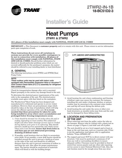
<strong>Install</strong>er’s <strong>Guide</strong><strong>2TWR2</strong>-IN-1B18-BC51D2-3Heat Pumps2TWR1 & <strong>2TWR2</strong>ALL phases of this installation must comply with NATIONAL, STATE AND LOCAL CODESIMPORTANT — This Document is customer property and is to remain with this unit. Please return to service informationpack upon completion of work.These instructions do not cover all variations insystems nor provide for every possible contingency tobe met in connection with installation. All phases ofthis installation must comply with NATIONAL, STATEAND LOCAL CODES. Should further information bedesired or should particular problems arise which are notcovered sufficiently for the purchaser’s purposes, the mattershould be referred to your installing dealer or local distributor.A. GENERALThe following instructions cover 2TWR1 and <strong>2TWR2</strong> HeatPump Units.NOTE:These outdoor units may be used with indoor unitsequipped with Thermostatic Expansion Valve or AccutronFlow Control Check Valve (F.C.C.V.) assembly for refrigerantflow control only.15 FT. ABOVE UNIT-UNRESTRICTEDCheck for transportation damage after unit is uncrated.Report promptly, to the carrier, any damage found to the unit.To determine the electrical power requirements of the unit,refer to the nameplate of the unit. The electrical poweravailable must agree with that listed on the nameplate.The Weathertron ® Heat Pump has been designed andmanufactured to withstand and operate in severe winterconditions. However, there are precautionary steps whichshould be taken at the time of installation which will helpassure the efficient operation of the unit. It is recommendedthat these precautions be taken for unitsbeing installed in areas where snow accumulation andprolonged below freezing temperatures occur.1. Units should be elevated 3 to 12 inches above the pad orrooftop, depending on local weather. This additionalheight will allow better drainage of snow and ice (meltedduring defrost cycle) prior to its refreezing. This shouldprevent a build-up of ice around the unit which occurswhen unit is not elevated. Insure that drain holes inunit base pan are not obstructed preventingdraining of defrost water.2. If possible, avoid locations that are likely to accumulatesnow drifts. If not possible, a snow drift barrier should beinstalled around the unit to prevent a build-up of snowon the sides of the unit and should be of sufficientdistance from the unit to prevent restriction of airflow toand from the unit. Also allow for proper maintenancespace. The barrier should be constructed of materialswhich will blend in with the building design.3. Avoid locating the unit where condensation and freezingof defrost vapor may annoy the customer. For instance,installing the unit under a bedroom, kitchen, or picturewindow may be annoying to the customer since condensateand fog will occur during the defrost cycle.4. Avoid locating the unit under the eaves or other overheadstructures as sizeable icicles may form and the unitmay be damaged by these falling icicles.B. LOCATION AND PREPARATIONOF THE UNIT1. When removing unit from the pallet, notice the tabs onthe basepan. Remove tabs by cutting with a sharp tool asshown on page 2, Figure 2, and slide unit off of pallet.2. The unit should be set on a level support pad at least aslarge as the unit base pan, such as a concrete slab. If thisis not the application used please refer to applicationbulletin “Trane APB2001-02”.3. The support pad must NOT be in direct contact with anystructure. Unit must be positioned a minimum of 12"from any wall or surrounding shrubbery to insureadequate airflow. Clearance must be provided in front ofcontrol box (access panels) and any other side requiringservice access to meet National Electrical Code. Also, theunit location must be far enough away from any struc-
<strong>Install</strong>er’s <strong>Guide</strong>2BASEPAN TAB REMOVALture to prevent excess roof run-off water from pouringdirectly on the unit. Do not locate unit(s) close tobedroom(s).4. The top discharge area must be unrestricted for at leastfive (5) feet above the unit.5. When the outdoor unit is mounted on a roof, be sure theroof will support the unit’s weight. Properly selectedisolation is recommended to prevent transmission to thebuilding structure.6. The maximum length of refrigerant lines from outdoorto indoor unit should NOT exceed sixty (60) feet.7. If outdoor unit is mounted above the air handler, maximumlift should not exceed sixty (60) feet (suction line). Ifair handler is mounted above condensing unit, maximumlift should not exceed sixty (60) feet (liquid line).8. Locate and install indoor coil or air handler in accordancewith instruction included with that unit.C. ACCUTRON FLOW CONTROL VALVEIf the indoor unit System Refrigerant Flow control is anAccutron orifice and check valve assembly, an orifice sizechange may be necessary.The outdoor model determines the required orifice size.Check the listed orifice size on nameplate of the selectedoutdoor model. If the indoor unit is factory shipped with adifferent orifice size, the orifice must be changed to obtainsystem rated performance.IMPORTANT:The outdoor unit is shipped with the proper size orifice and astick-on orifice size label in an envelope attached to theoutdoor unit. Outdoor unit nameplate will have correct orificesize specified as BAYFCCV --- A for rated performance.BRAZE TYPE INDOOR END3SEALING CAPACCUTRON TMCOMPONENTSD. INSTALLING REFRIGERANT LINES▲!CAUTIONIf using existing refrigerant lines make certain that all jointsare brazed, not soldered.Condensing units have provisions for braze connections.Pressure taps are provided on the service valves of outdoorunit for compressor suction and liquid pressures.The indoor end of the recommended refrigerant line sets maybe straight or with a 90 degree bend, depending uponsituation requirements. This should be thoroughly checkedout before ordering refrigerant line sets.The gas line must always be insulated.▲!CAUTIONIn scroll compressor applications, dome temperatures maybe hot. Do not touch top of compressor, may cause minor tosevere burning.The units are factory charged with the system charge requiredwhen using fifteen (15) feet of connecting line. Unitnameplate charge is the same.Final refrigerant charge adjustment is necessary. Usethe Charging Charts in the outdoor unit Service Facts.1. Determine the most practical way to run the lines.2. Consider types of bends to be made and space limitations.NOTE:Large diameter tubing will be very difficult to rebend once ithas been shaped.3. Determine the best starting point for routing the refrigeranttubing - -INSIDE OR OUTSIDE THE STRUCTURE.4. Provide a pull-thru hole of sufficient size to allow bothliquid and gas lines.5. Be sure the tubing is of sufficient length.6. Uncoil the tubing --- do not kink or dent.7. Route the tubing making all required bends and properlysecure the tubing before making connections.8. To prevent a noise within the building structure due tovibration transmission from the refrigerant lines, thefollowing precautions should be taken:a. When the refrigerant lines have to be fastened to floorjoists or other framing in a structure, use isolationtype hangers.4LIQUID LINE SERVICE VALVEADAPTERFLOW CONTROLCHECK VALVE(F.C.C.V.) ORIFICEBODYAS SHIPPEDFIELD SUPPLIEDLIQUID LINE© 2002 American Standard Inc. All Rights Reserved 18-BC51D2-3
<strong>Install</strong>er’s <strong>Guide</strong>5GAS LINE BALL SERVICE VALVE6GAS LINE SERVICE VALVECAP1/4 TURN ONLYCOUNTERCLOCKWISEFOR FULL OPENPOSITIONUNIT SIDEOF VALVEVALVE STEMPRESSURE TAP PORTGAS LINE CONNECTIONCAPBODY6. Precautions should be taken to avoid heat damageto the pressure tap valve core during brazing. It isrecommended that the pressure tap port valvecore be removed and a wet rag wrapped aroundthe valve body.COOLINGCOREHEATINGNOTE:Use care to make sure that no moisture enters pressure tapport, while wet rag is being used.b. Isolation hangers should also be used when refrigerantlines are run in stud spaces or enclosed ceilings.c. Where the refrigerant lines run through a wall or sill,they should be insulated and isolated.d. Isolate the lines from all ductwork.E. SERVICE VALVE OPERATIONBRASS LIQUID AND GAS LINE SERVICE VALVESThe Brass Liquid and Gas Line Service Valves are factoryshipped in the seated position to hold factory charge. Thepressure tap service port (when depressed) opens only to thefield brazing side of the valve when the valve is in the seatedposition. The liquid line valve is not a back seating valve (seeWARNING below).▲!WARNINGExtreme caution should be exercised when opening theLiquid and Gas Line Service Valves. Turn valve stemcounterclockwise only until the stem contacts the rollededge. (See Figures 4 and 6) No torque is required.BRASS GAS LINE BALL SERVICE VALVEThe Brass Gas Line Service Valve is shipped in the closedposition to hold the factory refrigerant charge. The pressuretap service port (when depressed) opens only to the fieldbrazing side when the valve is in the closed position.The Gas Line Service Valve is full open with a 1/4 turn. SeeFigure 5.BRAZING REFRIGERANT LINES1. Remove lower access cover to access service valves.2. Before brazing, remove plugs from external copper stubtubes. Clean internal and external surfaces of stub tubesprior to brazing.3. Cut and fit tubing, minimizing the use of sharp 90° bends.4. Insulate the entire gas line and its fittings.5. Do NOT allow uninsulated liquid line to come in directcontact with bare gas line.NOTE:Precautions should be taken to avoid heat damage tobasepan during brazing. It is recommended to keep theflame directly off of the basepan.7. Use a Dry Nitrogen Purge and Brazing Alloy withoutflux when brazing the field line to the copper factoryconnection. Flow dry nitrogen into either valve pressuretap port, thru the tubing and out the other port whilebrazing.8. Braze using accepted good brazing techniques.LEAK CHECKIMPORTANT:Replace pressure tap port valve core before attaching hoses forevacuation.After the brazing operation of refrigerant lines to both theoutdoor and indoor unit is completed, the field brazedconnections must be checked for leaks. Pressurize throughthe service valve ports, the indoor unit and field refrigerantlines with dry nitrogen to 350-400 psi. Use soap bubbles orother leak-checking methods to see that all field joints areleak-free! If not, release pressure; then repair!SYSTEM EVACUATIONNOTE:Since the outdoor unit has a refrigerant charge, the gas andliquid line valves must remain closed.1. Upon completion of leak check, evacuate the refrigerantlines and indoor coil before opening the gas and liquidline valves.2. Attach appropriate hoses from manifold gauge to gasand liquid line pressure taps.NOTE:Unnecessary switching of hoses can be avoided and completeevacuation of all lines leading to sealed system can beaccomplished with manifold center hose and connectingbranch hose to a cylinder of HCFC-22 and vacuum pump.18-BC51D2-3 3
3. FRC_DFT = Forced Defrost (Short TEST_COMMON tothis pin for two (2) seconds to initiate a forced defrost.Remove the short after defrost initiates.)DEFROST CONTROL CHECKOUTNormal operation requires:a. LED on board flashing 1 time/second.b. 24V AC between R & Bc. 24V AC between Y & B with unit operatingd. Defrost initiation when FRC_DFT pin is shorted toTEST_COMMON pin.If a defrost control problem is suspected, refer to the serviceinformation in control box.▲!WARNINGDo NOT connect 24 VAC to T1 (ODS-A) terminal. ODS-Athermistor WILL BE BLOWN.H. COMPRESSOR START UPAfter all electrical wiring is complete, SET THE THERMO-STAT SYSTEM SWITCH IN THE OFF POSITION SOCOMPRESSOR WILL NOT RUN, and apply power by closingthe system main disconnect switch. This will activate thecompressor sump heat (where used). Do not change theThermostat System Switch until power has been applied forone (1) hour. Following this procedure will prevent potentialcompressor overload trip at the initial start-up.<strong>Install</strong>er’s <strong>Guide</strong>I. OPERATIONAL AND CHECKOUTPROCEDURESFinal phases of this installation are the unit Operational andCheckout Procedures which are found in this instruction onpage 8. To obtain proper performance, all units must beoperated and charge adjustments made in accordance withprocedures found in the Service Facts.J. ELECTRIC HEATERSElectric heaters, if used, are to be installed in the air handlingdevice according to the instructions accompanying theair handler and the heaters.K. START CONTROLSome models have quick start components which are factoryinstalled. For models that do not have factory installed startcomponents, provisions are made for a field installed start kitaccessory. When adding an accessory, follow the instructionsprovided with the kit.L. OUTDOOR THERMOSTATAn outdoor thermostat TAYSTAT250B may be field installed.For data, see wiring diagram attached to unit and instructionsheet packaged with outdoor thermostat.M. SEACOAST SALT SHIELDUnits installed within one mile of salt water includingseacoasts and inland waterways, require the addition ofBAYSEAC001 (Seacoast Kit) at the time of installation.IMPORTANT:See Limited Warranty information in Use and Care Manual.TYPICAL FIELD HOOK-UP DIAGRAMSNotes:1. Be sure power supply agrees with equipment nameplate.2. Power wiring and grounding of equipment must comply with local codes.3. Low voltage wiring to be No. 18 AWG minimum conductor.4. ODT-B must be set lower than ODT-A.5. If outdoor thermostats (ODT) are not used, connect W1 to W2 and W3.6. N/A to programmable thermostat.LEGENDFACTORY WIRINGFIELD WIRING18-BC51D2-3 5
<strong>Install</strong>er’s <strong>Guide</strong>2TWR1 & <strong>2TWR2</strong> OUTLINE DRAWINGNote: All dimensions are in MM (Inches).MODELS BASE FIG. A B C D E F G H J K2TWR1018A 2 2 651 (25-5/8) 724 (28-1/2) 651 (25-5/8) 5/8 1/4 127 (5) 57 (2-1/4) 180 (7-1/8) 44 (1-3/4) 457 (18)2TWR1024A 2 2 651 (25-5/8) 724 (28-1/2) 651 (25-5/8) 3/4 5/16 127 (5) 57 (2-1/4) 180 (7-1/8) 44 (1-3/4) 457 (18)2TWR1030A 2 2 730 (28-3/4) 724 (28-1/2) 651 (25-5/8) 3/4 5/16 137 (5-3/8) 65 (2-5/8) 210 (8-1/4) 57 (2-1/4) 457 (18)2TWR1036A 2 2 730 (28-3/4) 724 (28-1/2) 651 (25-5/8) 7/8 3/8 137 (5-3/8) 65 (2-5/8) 210 (8-1/4) 57 (2-1/4) 457 (18)2TWR1042A 3 2 832 (32-3/4) 829 (32-5/8) 756 (29-3/4) 7/8 3/8 137 (5-3/8) 86 (3-3/8) 210 (8-1/4) 79 (3-1/8) 508 (20)2TWR1048A 3 2 832 (32-3/4 829 (32-5/8) 756 (29-3/4) 1-1/8 3/8 137 (5-3/8) 86 (3-3/8) 210 (8-1/4) 79 (3-1/8) 508 (20)2TWR1060A 4 1 841 (33-1/8) 946 (37-1/4) 870 (34-1/4) 1-1/8 3/8 152 (6) 98 (3-7/8) 219 (8-5/8) 86 (3-3/8) 508 (20)<strong>2TWR2</strong>018A 2 2 651 (25-5/8) 724 (28-1/2) 651 (25-5/8) 5/8 1/4 127 (5) 57 (2-1/4) 180 (7-1/8) 44 (1-3/4) 457 (18)<strong>2TWR2</strong>024A 2 2 730 (28-3/4) 724 (28-1/2) 651 (25-5/8) 3/4 5/16 137 (5-3/8) 65 (2-5/8) 210 (8-1/4) 57 (2-1/4) 457 (18)<strong>2TWR2</strong>030B 2 2 832 (32-3/4) 724 (28-1/2) 651 (25-5/8) 3/4 5/16 137 (5-3/8) 65 (2-5/8) 210 (8-1/4) 57 (2-1/4) 457 (18)<strong>2TWR2</strong>036A 3 1 832 (32-3/4) 829 (32-5/8) 756 (29-3/4) 7/8 3/8 143 (5-5/8) 92 (3-5/8) 210 (8-1/4) 79 (3-1/8) 508 (20)<strong>2TWR2</strong>042A 3 1 832 (32-3/4) 829 (32-5/8) 756 (29-3/4) 7/8 3/8 143 (5-5/8) 92 (3-5/8) 210 (8-1/4) 79 (3-1/8) 508 (20)<strong>2TWR2</strong>048A 3 1 933 (36-3/4) 829 (32-5/8) 756 (29-3/4) 1-1/8 3/8 143 (5-5/8) 92 (3-5/8) 210 (8-1/4) 79 (3-1/8) 508 (20)<strong>2TWR2</strong>060A 4 1 1045 (41-1/8) 946 (37-1/4) 870 (34-1/4) 1-1/8 3/8 152 (6) 98 (3-7/8) 219 (8-5/8) 86 (3-3/8) 508 (20)From Dwg. 21D152898 Rev. 96 18-BC51D2-3
<strong>Install</strong>er’s <strong>Guide</strong>MOUNTING HOLE LOCATIONNote: All dimensions are in MM (Inches).NOTE: For model base size,see table on page 6.From Dwg. 21D152637 Rev. 118-BC51D2-3 7
<strong>Install</strong>er’s <strong>Guide</strong>CHECKOUT PROCEDUREAfter installation has been completed, it is recommended that the entire system be checked against the following list:1. Refrigerant Line, Leak checked .................................. [ ] 8. Supply registers and return grilles open and2. Suction Lines and Fittings properly insulated ........... [ ]unobstructed ............................................................... [ ]3. Have all Refrigerant Lines been secured andisolated properly? ........................................................ [ ]9. Return air filter installed ............................................ [ ]4. Have passages through masonry been sealed?If mortar is used, prevent mortar from cominginto direct contact with copper tubing ........................ [ ]5. Verify tightness of all electrical connects ................... [ ]6. Observe outdoor fan during on cycle for clearanceand smooth operation ................................................. [ ]7. Indoor coil drain line drains freely. Pour waterinto drain pan .............................................................. [ ]10. Thermostat thermometer is accurate. Checkagainst a reliable thermometer. Adjust perinstructions with thermostat ...................................... [ ]11. Is correct speed tap being used?(Indoor blower motor) ................................................. [ ]12. Operate complete system in each mode toinsure safe operation. .................................................. [ ]TROUBLESHOOTING CHART — WHAT TO CHECKSTUCK COMPRESSORLOW VOLTAGE FUSECONTACTOR COILTHERMOSTATCONTROL TRANSFORMERLOW VOLTAGE WIRINGCONTACTOR CONTACTSSTART RELAYSTART CAPACITORRUN CAPACITORCOMPRESSOR IOLHIGH VOLTAGE WIRINGPOWER SUPPLYWHAT TO CHECK MODECHECK VALVE LEAKINGSOV COIL DEFECTIVESOV LEAKINGREF. CIR. RESTRICTIONSRES. I.D. AIRFLOWSUPERHEATTXV STUCK OPENO.D. AIR RECIRCULATIONRES. O.D. AIRFLOWNONCONDENSABLESEXCESSIVE EVAP. LOADREF. OVERCHARGEREF. UNDERCHARGEINEFFICIENT COMP.DEFROST CONTROL DEF.DEFROST RELAY DEF.*SYSTEM FAULTSREFRIGERANT CIRCUITHead Pressure Too HighHead Pressure Too LowSuction Pressure Too HighSuction Pressure Too LowLiquid Refrig. Floodback (TXV)CHCCCCPSSPPPPSPP SHHHHPSSPPPSSSLiquid Refrig. Floodback(Cap. Tube)CHPPSSSSI.D. Coil FrostingCPS SHCompressor RunsInadequate or No Cooling/HtgELECTRICALCHSSPPS SSCompressor & O.D. FanWon’t StartCHPPPPSSPPSSPPPPCompressor Will Not StartBut O.D. Fan RunsCHPPSSPPSSSSSSPPO.D. Fan Won’t StartCompressor Hums But Won’t StartCompressor Cycles on IOLI.D. Blower Won’t StartCCCCPPPPPSSPSSPSSSPPSSSSP S P P S S SHHHHPPPPPSSPSSPSSSPPSSSSP S P P S SDEFROSTCUnit Won’t Initiate DefrostHCDefrost Terminates on TimeHCPUnit Icing UpHPS SC - Cooling H - Heating P - Primary Causes S - Secondary Causes - 3 Phase Only*SSPPSSSSSSSSSSSSPPPPPPSSSSSSSSSSSPPSSSSSSSSPPPPPPPSSPPPPLiterature Order Number <strong>2TWR2</strong>-IN-1BP.I. 2/03File NumberSupersedesStocking LocationSV-UN-S/SP-<strong>2TWR2</strong>-IN-1B<strong>2TWR2</strong>-IN-1API Louisville & Webb/Mason-HoustonTraneA business ofAmerican Standard Companieswww.trane.comTrane has a policy of continuous product and product data improvement and it reserves the right to changedesign and specifications without notice.


