

2TWR2_Install Guide.pdf - HVAC.Amickracing
2TWR2_Install Guide.pdf - HVAC.Amickracing
2TWR2_Install Guide.pdf - HVAC.Amickracing

Create successful ePaper yourself
Turn your PDF publications into a flip-book with our unique Google optimized e-Paper software.
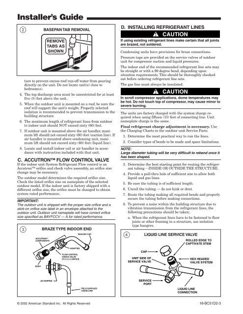
<strong>Install</strong>er’s <strong>Guide</strong>2BASEPAN TAB REMOVALture to prevent excess roof run-off water from pouringdirectly on the unit. Do not locate unit(s) close tobedroom(s).4. The top discharge area must be unrestricted for at leastfive (5) feet above the unit.5. When the outdoor unit is mounted on a roof, be sure theroof will support the unit’s weight. Properly selectedisolation is recommended to prevent transmission to thebuilding structure.6. The maximum length of refrigerant lines from outdoorto indoor unit should NOT exceed sixty (60) feet.7. If outdoor unit is mounted above the air handler, maximumlift should not exceed sixty (60) feet (suction line). Ifair handler is mounted above condensing unit, maximumlift should not exceed sixty (60) feet (liquid line).8. Locate and install indoor coil or air handler in accordancewith instruction included with that unit.C. ACCUTRON FLOW CONTROL VALVEIf the indoor unit System Refrigerant Flow control is anAccutron orifice and check valve assembly, an orifice sizechange may be necessary.The outdoor model determines the required orifice size.Check the listed orifice size on nameplate of the selectedoutdoor model. If the indoor unit is factory shipped with adifferent orifice size, the orifice must be changed to obtainsystem rated performance.IMPORTANT:The outdoor unit is shipped with the proper size orifice and astick-on orifice size label in an envelope attached to theoutdoor unit. Outdoor unit nameplate will have correct orificesize specified as BAYFCCV --- A for rated performance.BRAZE TYPE INDOOR END3SEALING CAPACCUTRON TMCOMPONENTSD. INSTALLING REFRIGERANT LINES▲!CAUTIONIf using existing refrigerant lines make certain that all jointsare brazed, not soldered.Condensing units have provisions for braze connections.Pressure taps are provided on the service valves of outdoorunit for compressor suction and liquid pressures.The indoor end of the recommended refrigerant line sets maybe straight or with a 90 degree bend, depending uponsituation requirements. This should be thoroughly checkedout before ordering refrigerant line sets.The gas line must always be insulated.▲!CAUTIONIn scroll compressor applications, dome temperatures maybe hot. Do not touch top of compressor, may cause minor tosevere burning.The units are factory charged with the system charge requiredwhen using fifteen (15) feet of connecting line. Unitnameplate charge is the same.Final refrigerant charge adjustment is necessary. Usethe Charging Charts in the outdoor unit Service Facts.1. Determine the most practical way to run the lines.2. Consider types of bends to be made and space limitations.NOTE:Large diameter tubing will be very difficult to rebend once ithas been shaped.3. Determine the best starting point for routing the refrigeranttubing - -INSIDE OR OUTSIDE THE STRUCTURE.4. Provide a pull-thru hole of sufficient size to allow bothliquid and gas lines.5. Be sure the tubing is of sufficient length.6. Uncoil the tubing --- do not kink or dent.7. Route the tubing making all required bends and properlysecure the tubing before making connections.8. To prevent a noise within the building structure due tovibration transmission from the refrigerant lines, thefollowing precautions should be taken:a. When the refrigerant lines have to be fastened to floorjoists or other framing in a structure, use isolationtype hangers.4LIQUID LINE SERVICE VALVEADAPTERFLOW CONTROLCHECK VALVE(F.C.C.V.) ORIFICEBODYAS SHIPPEDFIELD SUPPLIEDLIQUID LINE© 2002 American Standard Inc. All Rights Reserved 18-BC51D2-3


