eurorack 60 user man... - ADB Lighting Technologies
eurorack 60 user man... - ADB Lighting Technologies
eurorack 60 user man... - ADB Lighting Technologies
- No tags were found...

Create successful ePaper yourself
Turn your PDF publications into a flip-book with our unique Google optimized e-Paper software.
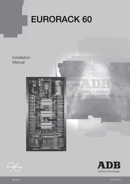
EURORACK <strong>60</strong>InstallationManual<strong>Lighting</strong> <strong>Technologies</strong>ME 31331106.03.133
EURORACK <strong>60</strong>SummaryDelivery - Unpacking 2Generalities - Safety 2Description 4Installation 5Characteristics 6Product Description 8Supply connections 11Operation on a Star system (3 x 400 V + N + Earth) 12Single-phase conversion kit 12Output Connections 12Control Connections 13Front-panel Controls 19Miscellaneous 22Installation of the Analogue Inputs kit 24Architectural Control 26Maintenance 31<strong>Lighting</strong> <strong>Technologies</strong>Installation - page 1R e v i s i o n : 0 0 3
EURORACK <strong>60</strong>Delivery - UnpackingUpon delivery of your equipment, open the packaging carefully and examine the EURORACK.If you observe any damage, contact the shipping company immediately, and have yourcomplaint duly recorded. You may rest assured that your equipment left the factory inperfect condition.Check whether what you have received is in conformity with the delivery notice, and whetherthe notice is in conformity with your order.In the event of any error, contact your shipper immediately to clarify the situation andreceive full satisfaction.If you find nothing wrong, replace the material in the packing and store it in a warm place,away from dust and humidity, while awaiting final installation.Never leave the material on the worksite under any circumstance.Generalities - SafetyThe EURORACK is a professional fully digital dimmer built in accordance with European safetystandards EN <strong>60</strong>950 and EN <strong>60</strong>204.It is a Class I equipment designed and <strong>man</strong>ufactured to EN <strong>60</strong>950 and requires imperatively asafety earth connection in compliance with local regulations.To prevent any risk of electric shock, do not remove any cover or part of the enclosure. Accessto internal parts is not required for normal operation.Refer servicing to skilled and trained service personnel exclusively.Disconnect from the power supply prior to opening for inspection or service.WARNING ! LETHAL VOLTAGES ARE PRESENT INSIDEWarning! Every <strong>user</strong> should read the chapter "Warning Messages"Connection to an inappropriate power source may irreversibly damage the EURORACK, it is the<strong>user</strong>’s responsibility to use the EURORACK for its intended purpose and to check the equipmentconnected to it.The EURORACK is a piece of professional equipment developed with the simplicity of use in mind.However, to obtain full benefits of the safety measures, the equipment shall be installed andserviced by skilled and trained personnel exclusively.Important Notice for Power CablesPower supply cables and connectors are an important part of your equipment and contribute toits safety.• always use an isolator or main circuit-breaker, or main fuses to interrupt the link; never pull onthe cable• do not damage the cable nor the connectors in any way, check them at each installation orat regular intervals in a per<strong>man</strong>ent installation• do not tie together power supply cables and signal cablesInstallation - page 2R e v i s i o n : 0 0 3<strong>Lighting</strong> <strong>Technologies</strong>
EURORACK <strong>60</strong>Very compact, all-digital intelligent dimmers, for professionalstage, studio and architectural lighting, whenever perfor<strong>man</strong>ce,space and cost are the prime considerations.Available in 3 main configurations:• 24 x 3 kW• 12 x 5 kWSupplied with:• instruction <strong>man</strong>ualMain Features• 5-key keypad, 12 character LED display and <strong>user</strong> friendlymenus for easy access to all dimmer functions• local controls for creation and storage of 20 (19+1) lightingcues• individual selection of dimmer address (patch), law, smoothingand multiplication factor• fade smoothing (4000-step resolution)• 10 dimmer laws selectable per dimmer• professional grade filtering (200 µs), for efficient attenuationof lamp filament noise• protection circuitry against accidental 400 V wiring• local status reporting: 400 V - overtemperature - fan failure- processor check - presence of DMX signal - DMX andanalogue control levels• hard-fired thyristors for control of tungsten halogen lamps,resistive and inductive loads, transformer-fed low voltagelamps, fluorescent lighting with suitable ballasts• heavy duty contactors for non-dimmable and special loads(HMI,…)• local test of a dimmer (steady, flash or chaser)• automatic self-test capability• high quality, low noise fans for effective cooling with automaticfan-stop• overtemperature protection through gradual dimmer fadeoutDimensions (mm) 1022 x 555 x 132Net weight (kg) 43Architectural ApplicationsThe analogue input option allows remote control by means of• analogue control desk (0/+10V), or• 3-position selector switch (up - down - steady), one switchcan control one or several dimmers, or• remote storage, playback and dimming of the 20 memories;direct access, one switch per memory<strong>Lighting</strong> <strong>Technologies</strong>Installation - page 3R e v i s i o n : 0 0 3
EURORACK <strong>60</strong>Options and Accessories• Supply protection per group of 30 kW (12 x 3 kW or 6 x 5 kW)compulsory for IT/TT supply. Required quantity: 6 for <strong>60</strong> kWRCD - 30 mA (3P+N)RCD30/ERACK• Supply protection per group of 30 kW (12 x 3 kW or 6 x 5 kW)compulsory for IT/TT supply. Required quantity: 2 for <strong>60</strong> kWRCD+MCB/1P+N-30mA - 6kA per dimmer- for 24 x 3 kW dimmers RCD+MCB/243- for 12 x 5 kW dimmers RCD+MCB/125• Stand-off brackets for 10 cm trunking space behind the rack (kit) ARC/ERACK• Cable entry panel with 27 universal entry seals and a steel PG31cable gland + additional cable support railsPANN.PG/ERACK• Main isolator switch 4P - 100 A INP.SWITCH/ERACK• Star/Delta power supply upon request• Dual DMX input retrofit kit (CPU board with data cables) KIT/2DMX/ERACKInstallation - page 4R e v i s i o n : 0 0 3<strong>Lighting</strong> <strong>Technologies</strong>
EURORACK <strong>60</strong>Protections• Individual protection by HRC (100 kA) 10.3 x 38 mm fusesfor absolute safety and system reliability under unpredictableconditions• Supply and "fuse OK" indicators integrated in the fuse-holder;slot for spare fuse• Protection avaibility against accidental 400 V wiring errorsconnections• Power supply on terminal strip (25 mm 2 )• Power output on terminal strip• Cable entry through the bottom side of the rack• Control signals on terminals• Switchable DMX line terminationLocal Controls without <strong>Lighting</strong> Console• Flashing of one dimmer for easy luminaire identification in arig• Chaser• Setting of a dimmer level• Creation, recording from DMX and editing of 20 lighting cuesPresentationCompact rack enclosure made of a very rigid assembly of steelplates, anodised aluminium extrusions and a smart looking frontcontrol panel.Front Panel LED Indicators :• Presence of DMX signal• Microprocessor running• Error messages in clear (for ex. temperature warning, fanfailure, …)Power Supply• Three phase star 3NPE 400 V, 50/<strong>60</strong> Hz (TN-S) with max.96 A per phase. Phase voltage 200 - 264 V.• Single-phase operation capability (1P protections).Optional single-phase 300 A supply terminal kit.Power RatingThe dimmers are suitable for continuous operation up to <strong>60</strong> kWtotal load at 35° C room temperature (air intake).Communications• DMX512/1990 digital input• 0/+10 V or 0/370 µA analogue inputs (option)• Please contact us for other multiplexed protocols• <strong>ADB</strong> Diagnostic Network (RS485) option, on 2 nd date pair inthe DMX cable.Cooling• Convection cooling via the lateral aluminium extrusions (heatsinks) and forced air cooling through two 12 V brushless DCfans with automatic ON-OFF switching• Overtemperature protection (gradual fade-out)Remote control and Diagnostic (option)• Selective diagnostic: microprocessor assisted automaticdetection of short-circuit, presence of load• Remote programming of the patch, dimmer law selection,smoothing, memorised cues. Remote reporting of Diagnosticcheck (if applicable)InstallationEURORACK <strong>60</strong> is primarily intended for wall mounting.Being significantly smaller and lighter than comparable systems,it can be installed on relatively light structures in a minimum ofspace.Installation work is very simple and limited to connecting DMX,power supply and power output cables to professional gradeterminal strips provided inside the enclosure.Support hardware is available for installations where cables haveto be run behind the EURORACK <strong>60</strong>.<strong>Lighting</strong> <strong>Technologies</strong>Installation - page 5R e v i s i o n : 0 0 3
EURORACK <strong>60</strong>CharacteristicsYour EURORACK is a piece of professional equipment, and should always be used in accordancewith applicable safety regulations.Electrical characteristicsControl electronicsRatingsOperating temperature rangeSupply system: fully digital, microprocessor controlled: dimmers rated for continuous duty : 24 x 3 kW; 12 x 5 kWmax <strong>60</strong> kW per EURORACK at 35°C: + 5° C to 35° C, 25° C suggested; relative humidity max.95%, non-condensing; altitude < 1000 m: 3NPE 400 V 50 Hz and <strong>60</strong> Hz (TN-S system, Neutral directlyconnected to Earth; 230 V between phase and Neutral)Reduced-size N conductor is not allowedSingle-phase operation is possible (single-pole protected)Supply voltage range : 198 V to 264 V (230 V ± 14 %)Accidental 400V supply: internal protection circuitry will disable the dimmersRated supply current : • Star 3-phase 3NPE supply: 87 A per phase at 230 V• single-phase supply: 261 A at 230 VDimmer protection: single-pole fuses, 10 x 38 mm, HRC (100 kA)Residual Current Device : • RCB or RCD+MCB per group of 4 x 3 kW or 2 x 5 kW;(OPTION)30 mA• RCB or RCD+MCB per group of 12 x 3 kW or6 x 5 kW; 30 mAControl inputs : • DMX512/1990 (USITT digital multiplex standard)• optional analogue 0/+10V or 0/+370 µA (internalconversion)• simultaneous DMX and analogue inputs:Highest Takes PrecedenceDMX control signal failure: the last valid DMX message will be kept indefinitelyDMX address : • setting of the DMX-address of the first dimmer bymeans of Menu• individual setting (patch)Dimmer laws : • linear rms voltage, linear to 120 V, fluorescent lighting,(selectable per dimmer)linear with 5% preheat level, square law, TV, non‐dim(on at 15 %), and 3 spare / special• multiplication factor per dimmerFront panel indicators : • "channel fuse is OK" per dimmer• presence of DMX512 control signal• microprocessor operational• fault messages (display)Dimmer test functions : • automatic chaser at 70%• one dimmer at any level• lighting cue without a desk• self-test (internal)Installation - page 6R e v i s i o n : 0 0 3<strong>Lighting</strong> <strong>Technologies</strong>
EURORACK <strong>60</strong>Response time : • DMX: better than 35 ms (typical)• analogue: better than 40 ms (typical)• dimmer precision : 4000 dimmer levelsPower semiconductors: antiparallel thyristorsEfficiency at rated load : better than 98 %Dissipation per dimmer atrated loadDC component in outputvoltageMinimum loadTypes of loadFault current rating: below <strong>60</strong> W (3 kW) and 100 W (5 kW): below 1 V in rated load range: 45 W for a 3 kW; <strong>60</strong> W for a 5 kW; typical : 25 W: suitable for resistive and inductive loads, such as tungstenlamps, low voltage halogen lamps with a suitable transformer,fluorescent lamps with suitable ballast.: dimmer fuses : 100 kAColour code for supply cable : - Brown and/or black : phases L1, L2, L3- Blue : Neutral- Yellow/green : EarthSafety standards : • EN<strong>60</strong>204• EN<strong>60</strong>950Mechanical characteristicsDimensions : 1020 x 135 x 555 mmBNet WeightPacking: 43 kg: 1150 x 265 x 685 mmGross Weight : 48 kgAC<strong>Lighting</strong> <strong>Technologies</strong>Installation - page 7R e v i s i o n : 0 0 3
EURORACK <strong>60</strong>Product DescriptionDigital dimmersEURORACK is a member of a family of fully digital dimmerpacks, using advanced microprocessorcontrol and an Application Specific Integrated Circuit (= custom chip) designed by <strong>ADB</strong>.Digital control offers stable, accurate and repeated perfor<strong>man</strong>ce over time, without the periodicalrecalibration required by dimmers with analogue circuitry.The very straightforward menu-driven set-up provides maximum flexibility for a wide range ofapplications.In a EURORACK equipped with the Analogue Input option, the analogue control signals areconverted to a digital signal by the DAC (Digital to Analogue Converter), and are further processedas digital data.The analogue and the DMX levels are merged for every dimmer, on a "highest takes precedence"(HTP) basis.Example :• dimmer - DMX control desk at 70 %- analogue control desk at 50 %- dimmer output level will be 70 %• dimmer - DMX control desk at 20 %- analogue control desk at 80 %- dimmer output level will be 80 %DMX Signalfrom a deskDMX Signalto an otherEURORACKSignalfrom ananaloguedeskInstallation - page 8R e v i s i o n : 0 0 3<strong>Lighting</strong> <strong>Technologies</strong>
EURORACK <strong>60</strong>RatingsYour EURORACK is suitable for continuous duty with a total load of <strong>60</strong> kW and 35°C ambienttemperature.Each individual dimmer is suitable for continuous duty at 3 kW and 5 kW respectively.When totalling up the load to a dimmer, one should include the losses in the cabling and, ifapplicable, the losses in the transformer.The factory-fitted fuses have carefully been selected for optimum protection of the semiconductorsand the cabling, for maximum safety and reliability.Do not use types other than supplied for the EURORACK .The factory-supplied fuses and spare-parts are selected for continuous operation at the rateddimmer load (3 kW, 5 kW). Some fuses may be labelled at lower values, e.g. 12 A for a 3 kWdimmer, due to the different fuse <strong>man</strong>ufacturers' rating systems and thermal fusing characteristics.LoadsThe use of oversized antiparallel thyristors (rather than triacs) and an appropriate gate firing techniquemakes your EURORACK suitable for a wide range of resistive and inductive loads, including tungstenlamps, low-voltage lamps with a suitable transformer, fluorescent lamps with a suitable ballast.The following precautions improve the reliability and perfor<strong>man</strong>ce of dimmer systems in general:• every low-voltage transformer must be protected by its own primary fuse• use preferably more than one lamp on the secondary of a low-voltage transformer• power-factor correction capacitors, such as supplied with some fluorescent lamp fixtures,should not be connected to a dimmer; they must be connected to the mainsCoolingYour EURORACK is equipped with a forced ventilation system, with two long-life, low-noise, highperfor<strong>man</strong>ce fans. This allows continous use at full rated load. Air intake apertures are on the front,and the exhaust apertures are on the top. Do never obstruct these apertures !The operation of the fans is controlled by microprocessor.The automatic thermal protection scheme is detailled in "Miscellaneous - Gradual Shutdown".The upper front panel covers :• the digital microprocessorelectronics• the fans• the internal fusesThe central front panel coversthe power electronics(thyristors)The lower front panel coversthe contractor's area with :• the supply terminals• the load terminals• the control terminals<strong>Lighting</strong> <strong>Technologies</strong>Installation - page 9R e v i s i o n : 0 0 3
EURORACK <strong>60</strong>Wall-mountingEURORACK will be mounted against a wall, with cable entry at the bottom.A wall-mounting kit is available if the EURORACK is to be mounted away from the wall, therebycreating trunking space behind the EURORACK.Distance between adjacent EURORACKsA distance of min. 50 mm (2") should be kept between adjacent EURORACKs.This will allow sufficient airflow along the side panels (= heatsinks).Installation - page 10R e v i s i o n : 0 0 3<strong>Lighting</strong> <strong>Technologies</strong>
EURORACK <strong>60</strong>Supply connectionsType of mains supply networkBefore you connect electrical equipment, you must verify that it is adapted to the mains systemat your venue.If in doubt consult the electrician or the utility company.The standard EURORACK is suitable for a three-phase 3NPE 400V 50Hz and <strong>60</strong>Hz, TN-S system(three phase wires + Neutral wire + Earth wire; Neutral directly connected to Earth).The rated voltage between phase and Neutral is 230 V.The operating voltage range is 230 V ± 14% (198 V to 264 V).The dimmer protections are single-pole, in the Live wire, as required for a three-phase TN-S supply.1P + N and 2 P dimmer protection available on request.Under some conditions, the EURORACK can be operated on a single-phase supply.Details are described in "Single-phase conversion kit".Protection on the supply sideEURORACK and its supply cable must be adequately protected against overload and short-circuitby the installation; verify the current edition of the applicable wiring regulations.Please also refer to “Supply Cable”, and to “Electrical Characteristics”.Supply terminalsAll connections should be performed by a qualified electrician.The supply terminals are suitable for cables up to 25 mm 2 .The colour code is blue for Neutral and yellow/green for PE.Access to the terminals• the lower front panel must be removed to gain access to the supply terminals.• always disconnect the power supply before you remove the cover• please refer to the sketch for the position of the four screws which secure the cover.Supply cableThe size of the Neutral wire must at least be equal to the size of the phases; reduced-sizeNeutral wires are DANGEROUS and are NOT allowed.All supply cables and extension cables should have all conductors under the same sleeve, in orderto reduce unwanted interferences to audio and video equipment.The supply cable should be sized for the rating of the EURORACK:• 87 A per phase for three-phase star operation (3 x 400 V + N)• 153 A per phase for delta supply (3 x 230 V)• 261 A for single-phase operation (230 V + N)Cables for lower current ratings are not allowed unless the protection devices in the installation(supply fuses or supply circuit-breaker) are selected accordingly.<strong>Lighting</strong> <strong>Technologies</strong>Installation - page 11R e v i s i o n : 0 0 3
EURORACK <strong>60</strong>Operation on a Star system (3 x 400 V + N + Earth)PESingle-phase conversion kitThe EURORACK can under some circumstances (see Warning below) be used on a single-phasesupply. L1, L2 and L3 are linked for single-phase operation.WARNINGThe EURORACK (TN version) will operate on a single-phase supply, but the <strong>user</strong> must verifywhether single-pole protections are allowed by the applicable wiring regulations.The EURORACK will operate reliably up to its full rated load (<strong>60</strong> kW) at 35°C. The actually availablepower may be limited by the power supply (cable size, supply fuse rating, supply mcb rating).Output ConnectionsThe outgoing cables to the luminaires areconnected to the terminal strip in the contractor'spanel.Phase, neutral and PE terminals are supplied foreach dimmer.All load terminals are clipped on a symmetrical35 mm ("top-hat") DIN rail.The terminals are suitable for wire sizes (strandedor rigid) :• for 3 kW dimmers: up to 4 mm 2• for 5 kW dimmers: up to 6 mm 2NumberingThe pre-printed numbering on the terminals refersto the pre-printed numbering of the dimmer fuseson the front panel.Both indicate the number of the dimmer.Installation - page 12R e v i s i o n : 0 0 3<strong>Lighting</strong> <strong>Technologies</strong>
EURORACK <strong>60</strong>Control ConnectionsTwo lighting control desks can simultaneously control your EURORACK: one DMX512 and oneAnalogue. The actual dimmer output will be the highest of the two levels (Highest Takes Precedence,HTP), as described in the example on page 5.DMX512/1990DMX512 (USITT) is internationally the most widely accepted communication standard for lightingcontrol equipment. The standard is issued by the USITT (U. S. Institute of Theatre Technology);the suffix 1990 indicates the latest issue.The DMX512 signal is a Digital MultipleXed control signal, suitable for the digital transmission ofthe levels of up to 512 dimmers.Electrically it uses the RS-485 (EIA-485) standard, which states: wire pairs + screen; maximum 32receivers on a line; cable length without reamplification max. 300 m; no splitting or Y-junctions.Transmission rate is high (250 kbit/s). Dimmer levels are sent in bytes of 8 bits (256 possible levels).Standard DMX interconnectionand extension cableCableLength: recommended max. 250 mSize: 2 x 2 x 0.34 mm 2 , shieldedThe terminating resistor must beplaced on the output connectorof the last unit on the DMX line.DMX512 networkThe EURORACK is fitted with a small PCB 1357, with two terminal strips (IN and OUT) for a daisychainDMX512 network (see example 1). IN and OUT are wired through internally.The terminal numbering is identical to the numbering of XLR5 connectors for DMX :1 = screen2 = DMX data -3 = DMX data +4 = spare -5 = spare +Termination of the DMX lineThe DMX OUT of the last dimmer unit on the daisy-chain must receive a termination resistor.• If the last unit on the daisy-chain is a EURORACK, then EURORACK can provide termination:set W on PCB 1357 to ON, for the last EURORACK on the DMX line.• If the last unit on the daisy-chain is a portable dimmer, e.g. MEMOPACK, then it must beequipped with a termination plug. This termination plug is an XLR5 plug with small resistorsof 120 Ω 0,33 W soldered between pins 2 and 3 and between pin 4 and 5 (for the comm.network). A diagram is shown at the end of this <strong>man</strong>ual.The DMX512 networkThe DMX512 network starts from the lighting control desk. A first cable runs from the DMX OUT ofthe control desk to the DMX IN of the nearest dimmer unit. The daisy-chain continues by meansof a second cable, connecting DMX OUT to DMX IN of the next dimmer unit. This daisy-chain iscontinued through all the dimmer in the system. In EURORACK the DMX IN and DMX OUT arewired in parallel, so continuity of the daisy-chain is always provided. The continuity and quality ofthe DMX signal will not be affected when the EURORACK is switched off, or when a failure occurs.Opto-isolationThe DMX512 input of your EURORACK is equipped with optocoupler isolation. This provides galvanicisolation between the DMX network and the microprocessor electronics in the EURORACK. Thisis an important safety feature: should for example the DMX512 network come in contact with 230V mains voltage, then the internal electronics of the EURORACK will remain isolated from thosedangerous voltages. Such accident could occur for example when cables are severely damaged orcrushed, or when an isolation fault occurs in a control desk which has no opto-isolation in its output.<strong>Lighting</strong> <strong>Technologies</strong>Installation - page 13R e v i s i o n : 0 0 3
EURORACK <strong>60</strong>DMX Network - Application ExamplesNOLIGHTINGCONTROLDESKDMX 512more than 250 mDIMMERLIGHTINGCONTROLDESKDMX 512DIMMER 1DIMMER 2DIMMER 3YES1 - When total length of DATA line exceeds the recommended length :- DMX 512 Standard : 300 m- <strong>ADB</strong> recommendation : 250 mDATABOOSTERLIGHTINGCONTROLDESKAUX 1DIMMERless than 250 m less than 250 m2 - When DATA line is split in a Y - junctionLIGHTINGCONTROLDESKless than 250 mDATABOOSTERAUX 1AUX 2AUX 3less than 250 mDIMMER 1DIMMER 2DIMMER 33 - Galvanic isolation for DATA line protectionDATABOOSTERControl deskwithoutAUX 1galvanic less than 250 mless than 250 misolationDIMMERInstallation - page 14R e v i s i o n : 0 0 3<strong>Lighting</strong> <strong>Technologies</strong>
EURORACK <strong>60</strong>Example 1: four EURORACKs (24 dimmers) controlled by a lighting control deskAdresse 025 :Dimmers : 25 to 48Adresse 049 :Dimmers : 49 to 72Adresse 001 :Dimmers : 1 to 24Adresse 073 :Dimmers : 73 to 96DMX OutHow to lay-out the DMX512 cables• the EURORACKs can be daisy-chained in any order (see example 1)• the last unit on the DMX line must be equipped with a Termination Plug or resistor• the overall length of the DMX cables (sum of the length of the individual cables) is very important.We recommend that it should not exceed 250 m. Longer cable runs are likely to reduce thequality of the DMX signal, which may result in unpredictable results. For cable runs exceeding250 m an active amplifier is required, such as <strong>ADB</strong>’s DATA BOOSTER. A 250 m cable run canbe connected to each active output of the DATA BOOSTER.• Y-splitting is not allowed. If the DMX network must fan out in different directions, then an activesplitter is required, such as <strong>ADB</strong>’s DATA BOOSTER• the DMX512 standard states that max. 32 receiver units may be connected to one transmitter.So up to 32 EURORACKs can be connected to a lighting control desk, or to an active outputof a DATA BOOSTER/SPLITTER• do not run DMX512 cables (or Analogue control cables) together with power cables• for further information, please refer to the data sheet of the DATA BOOSTER, or the"Recommended Practice for DMX512" published by the Professional Light and SoundAssociation (PLASA) available from your supplier.<strong>Lighting</strong> <strong>Technologies</strong>Installation - page 15R e v i s i o n : 0 0 3
EURORACK <strong>60</strong>Example 2 : one EURORACK, with Analogue Input Option, controlled by an analogueoutput deskMax. 10 AAnalogue230 V / 400 V230 VExample 3 : one EURORACK, with Analogue Input Option, controlled simultaneouslyby an analogue output desk and a multiplexed desk (Highest TakesPrecedence)Max. 10 A230 V / 400 VDMXAnalogue230 V230 VInstallation - page 16R e v i s i o n : 0 0 3<strong>Lighting</strong> <strong>Technologies</strong>
EURORACK <strong>60</strong>Example 4 : one EURORACK controlled by a DMX desk, which also controls DMXcolour scrollers (GELBUS)Max. 10 AGelbusPower supply230 V230 V / 400 VDMX to an otherGelbus Power supplyDMX230 V<strong>Lighting</strong> <strong>Technologies</strong>Installation - page 17R e v i s i o n : 0 0 3
EURORACK <strong>60</strong>Analogue inputsYour EURORACK can be equipped with Analogue Inputs, in which case it can be controlled byanalogue control signals, 0/+10V or 0/+370 µA (filtered).If the Analogue Inputs were factory-installed, they were set for 0/+10V operation; you can easilyperform the conversion to 0/+370 µA yourself. See below for the detailed procedure.The Analogue Inputs connector is a DB25-S receptacle, in the contractor's compartment.The following table shows the pin allocation for all the connectors, including P3 and P4 on theAnalogue Inputs board.DB‐25 S internal (P3, P4)control dimmer 1 pin 1 pin 1control dimmer 2 pin 2 pin 3control dimmer 3 pin 3 pin 5control dimmer 4 pin 4 pin 7control dimmer 5 pin 5 pin 9control dimmer 6 pin 6 pin 11control dimmer 7 pin 7 pin 13control dimmer 8 pin 8 pin 15control dimmer 9 pin 9 pin 17control dimmer 10 pin 10 pin 19control dimmer 11 pin 11 pin 21control dimmer 12 pin 12 pin 23control dimmer 13 pin 13 pin 25control dimmer 14 pin 14 pin 2control dimmer 15 pin 15 pin 4control dimmer 16 pin 16 pin 6control dimmer 17 pin 17 pin 8control dimmer 18 pin 18 pin 10control dimmer 19 pin 19 pin 12control dimmer 20 pin 20 pin 14control dimmer 21 pin 21 pin 16control dimmer 22 pin 22 pin 18control dimmer 23 pin 23 pin 20control dimmer 24 pin 24 pin 220 V pin 25 pin 24 and 26Internal setting for Analogue Inputs• setting for 0/+10 V operation: the ribbon cable with the front-panel DB-25-S Analogue receptacleis plugged into P3 on the Analoge Input board PCB 1336• setting for 0/+370 µA operation: the ribbon cable with the front-panel DB-25-S Analoguereceptacle is plugged into P4 on the Analoge Input board PCB 1336• W1 on PCB 1336: jumper removed, or placed between pin 2 and pin 3• W2 on PCB 1336: jumper removed, or placed between pin 2 and pin 3Analogue Inputs : selection 0/+10 V or 0/370 µAYour EURORACK was factory-set for 0/+10V analogue control signals. To convert it to 0/+370µAplease refer to qualified personnel:• disconnect the EURORACK from the mains• remove the top cover, see the sketch in the Supply Connections Chapter• touch the aluminium heatsink to discharge electrostatic build-up• identify on the small Analogue Inputs board (PCB 1336) connector P3, labelled 0->10V• remove the 25-wire flat (ribbon) cable from that connector• connect the 25-wire flat (ribbon) cable to connectorP4, labelled 0->370µA• secure the connector• close the coverInstallation - page 18R e v i s i o n : 0 0 3<strong>Lighting</strong> <strong>Technologies</strong>
EURORACK <strong>60</strong>Front-panel ControlsFuse and Power IndicatorsThe indicator which is integrated in the fuse-holder shows theactual supply to each dimmer: power is on, the dimmer fuse isin good condition.Phase DistributionThe dimmers are supplied from alternating phases :• dimmer 1 is supplied from phase L1• dimmer 2 is supplied from phase L2• dimmer 3 is supplied from phase L3• dimmer 4 is supplied from phase L1• dimmer 5 is supplied from phase L2• dimmer 6 is supplied from phase L3• etc…• the microprocessor electronics are supplied from phase L1L1L2Status IndicatorsRun : the microprocessor is operational if this LED flashesapprox. once per second.Other blinking modes refer to special functions,memory control, remote programming.L3Examples: Flash Flash Flash Pause: remote memory control"Special 3".Flash Flash Flash Flash Pause: remote memorycontrol "Special 4".DMX :this LED indicates the presence of a multiplexedsignal on the DMX input; this can also be used tolocate short-circuits in your DMX 512 data cablesSoftware functions and menusPlease refer to the Short Form Manuel or "Programming DigitalDimmers".<strong>Lighting</strong> <strong>Technologies</strong>Installation - page 19R e v i s i o n : 0 0 3
EURORACK <strong>60</strong>Putting into OperationPower sectioncheck type ofpowersupply network( 3 x 400 / 230 V+ N + earth)connect to mainscheck the indicatorsin the fuse-holdersall are lit :the 3 phasesare presentcheck displaynone is litsome indicatorsdo not lightdisplay Address :check the "run" LEDblinksDisplays 400 V !!disconnect powerimmediately :overvoltage !!check the Neutral !• no power• check connectionand fuses in theswitchboard• check the RCDNote:• dimmers 1 and 4are on phase L1• dimmers 2 and 5are on phase L2• dimmers 3 and 6are on phase L3connect the spotlightsto the dimmersalways ONalways OFFcheck display• set Menu 2• start Test Chaserto reset :disconnect power;wait 5 seconds;reconnect powerdisconnect powerimmediately; checkfor errors in supplycablesmessage"No phase L2" or "Nophase L3"no messageat alleach dimmerfades up/downNo response for somedimmerscheck internalfuses F1 to F5the EURORACKis functioning ;connect it tothe control desk• leave Test Chaser• set addresscheck :• dimmer fuse• cable to spotlights,lamps* When a dimmer protection tripped, first check thetotal load (Wattage) connected to the correspondingdimmer, check the lamps and the cables of thespotlights, check that the ambient temperatureis not too high; disconnect EURORACK and thenreplace the dimmer fuse.• the correspondingphase is missing• the EURORACKfunctions, butdimmers connectedto the missingphase do notfunction• check theconnection to themains and fuses inthe switchboard• phase L1 is missing• the EURORACKcannot function asthe electronics areconnected to thisphase• check theconnection to themains and fusesin the switchboardInstallation - page 20R e v i s i o n : 0 0 3<strong>Lighting</strong> <strong>Technologies</strong>
EURORACK <strong>60</strong>Putting into OperationOperating sectionConnect theEURORACKto the control deskinterconnect theEURORACKSConnectline termination plugto last DMX deviceOperate the dimmersat 50 % (use the desk)multiplexed signalanalogue signalcheck the DMX LEDthe spotlightslitnot litlight updo not light upsome light updefine the address (ofthe first dimmer) oneach EURORACKthe installation isready to functionlitthere is a shortfurther down theDMX data line(cable or pack)define the address (ofthe first dimmer) oneach EURORACKthe installationis ready to functiondisconnect theOUT data cablecheck the DMX LEDnot lit• the signal is notreaching theEURORACK- is the deskpowered-up?- is the desk operatingthe channels with avalue other than zero?- check the line betweenthe desk and theEURORACK andthe line to the otherpacksthe installation isready to function• the signal is notarriving- is the deskpowered-up ?- is the desk operatingthe channels witha value otherthan zero ?- check the analogueline between thedesk and theEURORACK- Use Analog In ?(menu 2) to readthe incominganalogue signallevel for eachdimmerUse Analog In ? (menu2) to read the incominganalogue signal levelfor each dimmer• the signal is notarriving- is the deskpowered-up?- is the desk operatingthe channels witha value other thanzero?- check the analogueline between thedesk and theEURORACK<strong>Lighting</strong> <strong>Technologies</strong>Installation - page 21R e v i s i o n : 0 0 3
EURORACK <strong>60</strong>MiscellaneousProtection against accidental 400 VWarning : always check the mains voltage before you connect power to electrical equipment.If excessive voltages are applied, the internal protection circuitry of your EURORACK will disablethe EURORACK.If the excessive voltage was applied for a relatively brief period (up to 1 minute), then the dimmerwill reset itself automatically.If the excessive voltage was applied for a long time, then the internal fuse(s) will trip.To restore normal operation:• disconnect the EURORACK from the mains• remove the upper front panel, see sketch in "Product Description" chapter• check the five fuses (5 x 20 mm) F1 through F5 - see sketch "Synchro board PVB 1355" -replace blown fuses by suitable type only• close the EURORACK• verify the power source; possible cabling errors include inversion between phase and Neutral,or disconnected Neutral• restore power to the EURORACK only when you are confident that the power source issatisfactory400 V MessageThis warns you that an excessive voltage is applied to at least one of the phases. The EURORACKhas shut itself down, no dimmer will operate.ACTIONS TO TAKE: see Warning Messages - 400 VLoss of DMX signal - time-outShould the DMX control signal disappear, then the microprocessor will keep the last levels indefinitely.Dimmer levels can always be brought back to “Off”• by restoring the DMX line• or by disconnecting the power to the EURORACK• or by entering the "Individual Dimmer Test" mode and setting a "0 %" levelSpare fusesThe fuse-holder features two slots: one for the dimmer fuse, one for a spare fuse.SparefuseDimmerfuseInstallation - page 22R e v i s i o n : 0 0 3<strong>Lighting</strong> <strong>Technologies</strong>
EURORACK <strong>60</strong>Microprocessor resetThe "Run" indicator on the front panel flashes at a rate of once per second, if the microprocessoris operational. Should the indicator stop blinking, then you can Reset the microprocessor bydisconnecting the power supply to the EURORACK.Use the supply isolator, the RCD or the MCB; never use the supply plug!Over-temperature - gradual shutdownYour EURORACK is equipped with a temperature monitoring system. Should the internal temperaturerise, then the display will show a flashing message (Over Temp.).Your EURORACK is rated for continuous duty, so a Over Temp. warning is an indication of faultyoperation or use.Please verify :• the room temperature (35°C max.)• that the air intake and exhaust apertures are not obstructed• that the air intake is not influenced by the warm air exhausted by other equipment• that the fans are still operational• that no dimmer is loaded to more than capacity (3 kVA or 5 kVA)Reduced dimmer levels or loads will reduce the internal heat dissipation.If the internal temperature remains too high for several minutes, then a TEMP message will flashand the EURORACK will protect itself by a gradual shutdown:• first all dimmer levels will be slightly reduced• followed later by further reductions of all dimmer levels• normal operation is automatically restored when a safe temperature is reached, and after resetInternal fusesIf the dimmer fuse indicators are lit, but the front panel LED’s nor the display light up, then youshould check the fuses for the control electronics. These fuses are independent of the dimmerprotections on the front panel. They can easily be reached (qualified personnel only !) :• disconnect the EURORACK from the mains• remove the upper front panel, see sketch in "Product Description"• check the five fuses (5 x 20 mm) F1 to F5 - see sketch "Synchro board PCB 1355"• replace fuses, if necessary; use suitable fuses only !• close the coverThe use of incorrect fuses is dangerous, may cause per<strong>man</strong>ent damage, and will void warranty.Correct fuse references are listed in the Maintenance chapter, Spare Part List.<strong>Lighting</strong> <strong>Technologies</strong>Installation - page 23R e v i s i o n : 0 0 3
EURORACK <strong>60</strong>Installation of the Analogue Inputs kitIf your EURORACK was not factory-equipped with the Analogue Inputs, you can upgrade it bymeans of a kit.PCB 1336 Analog Input board (optional)• disconnect the EURORACK from the mains• remove the upper front panel (4 screws, see sketch in "Product Description")• install board PCB 1336 (127 x 87 mm) + four plastic stand-offs• P1 on PCB 1336 (Analogue Input board) mates with P3 of PCB 1338(Microprocessor CPU board)• for 0/+10 V operation: connect the ribbon cable (25 conductors) with the front panel Analoguereceptacle (DB-25-S) to P3 on PCB 1336 (Analoge Input board)• 0/+370 µA operation: connect the ribbon cable (25 conductors) with the front panel Analoguereceptacle (DB-25-S) to P4 on PCB 1336 (Analogue Input board)• secure the ribbon cable in the central vertical plastic channel• close the cover• enable the Analogue Inputs, by means of the Analog In function in Menu 3PCB 1338 Microprocessor (CPU) boardInstallation - page 24R e v i s i o n : 0 0 3<strong>Lighting</strong> <strong>Technologies</strong>
EURORACK <strong>60</strong>Installation of the Analogue Inputs kitIf your EURORACK was not factory-equipped with the Analogue Inputs, you can upgrade it bymeans of a kit.PCB 1336 Analogue Input board (optional)• disconnect the EURORACK from the mains• remove the upper front panel (4 screws, see sketch in “Product Description”)• install board PCB 1336 (127 x 87 mm) + four plastic stand-offs• P1 on PCB 1336 (Analogue Input board) mates with P3 of PCB 1338 (Microprocessor CPUboard)• for 0/+10 V operation: connect the ribbon cable (25 conductors) with the front panel Analoguereceptacle (DB-25-S) to P3 on PCB 1336 (Analoge Input board)• 0/+370 µA operation: connect the ribbon cable (25 conductors) with the front panel Analoguereceptacle (DB-25-S) to P4 on PCB 1336 (Analogue Input board)• secure the ribbon cable in the central vertical plastic channel• close the cover• enable the Analogue Inputs, by means of the Analog In function in Menu 3PCB 1338 Microprocessor (CPU) board<strong>Lighting</strong> <strong>Technologies</strong>Installation - page 25R e v i s i o n : 0 0 3
EURORACK <strong>60</strong>Architectural ControlEURORACK <strong>60</strong> - 12 DimmersPushbutton Panel - Basic VersionFunction: fade a dimmer up and down (Special 1)12 buttons + upC&K 7015 - downDB25male toEURORACKDB25female(option) toanother buttonsJumper setting on Analogue Input Board - PCB1136• W1 between 1 and 2 (supplies + 10 V)• W2 between 1 and 2 (supplies + 5 V)Menu setting (Level 3)• Analogue Inpu Mode: Special 1Installation - page 26R e v i s i o n : 0 0 3<strong>Lighting</strong> <strong>Technologies</strong>
EURORACK <strong>60</strong>EURORACK <strong>60</strong> - 12 DimmersPushbutton Panel - with Master (Special 1)12 buttons + upC&K 7015 - downDB25male toEURORACKDB25female(option) toanother buttonsJumper setting on Analogue Input Board - PCB1136• W1 between 1 and 2 (supplies + 10 V)• W2 between 1 and 2 (supplies + 5 V)Menu setting (Level 3)• Analogue Input Mode: Special 1<strong>Lighting</strong> <strong>Technologies</strong>Installation - page 27R e v i s i o n : 0 0 3
EURORACK <strong>60</strong>EURORACK <strong>60</strong> - 24 DimmersPushbutton Panel - with Master (Special 1)12 buttons + upC&K 7015 - downFor EURORACK with 18 or 24dimmers, the + 5V and + 10Vrequired for the pushbuttons issupplied from connector P2 onthe "Analogue Input Board".The jumper W& and W2 on"Analogue Input Board -PCB1136" should be set asfollows :• W1 between 2 and 3(or removed)• W2 between 2 and 3(or removed)Menu setting• Analogue Input Mode:Special 1Note :This setting is identical to thefactory-setting for operationwith an analogue control desk.The analogue input ribboncable should be set in thesocket P3 "0 / + 10 V".DB25male toEURORACKDB25female(option) toanother buttonsP2 on PCB 1336Analogue InputsInstallation - page 28R e v i s i o n : 0 0 3<strong>Lighting</strong> <strong>Technologies</strong>
EURORACK <strong>60</strong>EURORACK <strong>60</strong> - 24 DimmersFor EURORACK with 18 or 24dimmers, the + 5V and + 10Vrequired for the pushbuttons issupplied from connector P2 onthe "Analogue Input Board".Pushbutton Panel - with "All Switch"Function: fading a dimmer up and down (Special 1)12 buttons + upC&K 7015 - downThe jumper W& and W2 on"Analogue Input Board -PCB1136" should be set asfollows :• W1 between 2 and 3(or removed)• W2 between 2 and 3(or removed)Note :This setting is identical to thefactory-setting for operationwith an analogue control desk.The analogue input ribboncable should be set in thesocket P3 "0 / + 10 V".DB25male toEURORACKDB25female(option) toanother buttonsP2 on PCB 1336Analogue Inputs<strong>Lighting</strong> <strong>Technologies</strong>Installation - page 29R e v i s i o n : 0 0 3
EURORACK <strong>60</strong>Wiring diagram for Special 3Analogue Input Board pcb 1336 - jumpersFor Special 3 and Special 4, jumper W1 of pcb 1336 must be set on pins 1 and 2, to provide adc voltage on pin 14 of the 25-pin connector. Jumper W2 must be positioned on pins 2 and 3;or must be removed.How to protect the cues ?To avoid accidental modification of cues by non-qualified staff, we recommend to connect the'Record' key only in selected locations such as the control room. As an additional precaution, youcan wire a key-switch in series with the Record key.record (in combination with a Cue key) pin 1stop playing cue; fade to DMX pin 2play next existing cue pin 3priority cue, No. 0 pin 4cue No. 1 pin 5cue No. 2 pin 6cue No. 3 pin 7cue No. 4 pin 8cue No. 5 pin 9cue No. 6 pin 10cue No. 7 pin 11cue No. 8 pin 12cue No. 9 pin 13+Vdc supply voltage pin 14cue No. 10 pin 15cue No. 11 pin 16cue No. 12 pin 17cue No. 13 pin 18cue No. 14 pin 19cue No. 15 pin 20cue No. 16 pin 21cue No. 17 pin 22cue No. 18 pin 23cue No. 19 pin 24ground; connect shields together and pin 25at dimmer; do not connect to the remote panelsInstallation - page 30R e v i s i o n : 0 0 3<strong>Lighting</strong> <strong>Technologies</strong>
EURORACK <strong>60</strong>Wiring diagram for Special 4Analogue Input Board pcb 1336 - jumpersFor Special 3 and Special 4, jumper W1 of pcb 1336 must be set on pins 1 and 2, to provide adc voltage on pin 14 of the 25-pin connector. Jumper W2 must be positioned on pins 2 and 3;or must be removed.How to protect the cues ?To avoid accidental modification of cues by non-qualified staff, we recommend to connect the'Record' key only in selected locations such as the control room. As an additional precaution, youcan wire a key-switch in series with the Record key.record (in combination with a Cue key) pin 1stop playing cue; fade to DMX pin 2play next existing cue pin 3priority cue, No. 0 pin 4cue No. 1 pin 5cue No. 2 pin 6cue No. 3 pin 7cue No. 4 pin 8cue No. 5 pin 9cue No. 6 pin 10cue No. 7 pin 11cue No. 8 pin 12cue No. 9 pin 13+Vdc supply voltage pin 14cue No. 10 pin 15cue No. 11 pin 16cue No. 12 pin 17cue No. 13 pin 18cue No. 14 pin 19cue No. 15 pin 20cue No. 16 pin 21fade the current cue Down pin 22fade the current cue Up pin 23start Memory Chaser at first existing cue pin 24ground; connect shields together and pin 25at dimmer; do not connect to the remote panels<strong>Lighting</strong> <strong>Technologies</strong>Installation - page 31R e v i s i o n : 0 0 3
EURORACK <strong>60</strong>MaintenanceWarningLethal voltages are used in this equipment. Refer servicing to trained personnel.Power must be disconnected before a fuse is removed.Power must be disconnected before a cover is removed.FusesThe dimmer fuses are placed on the front panel.The internal fuses for the microprocessor electronics are accessible by removing the top cover(see sketch "Supply Terminals").Always disconnect the power before you open the EURORACK or replace a fuse!Switch power off by means of the supply isolator, supply MCB or supply RCD..Always use fuses of the same type, size, current rating, fusing value (I2t value) and fault currentrating as the originals. Contact your supplier for spare parts.List of Accessories and Spare PartsAlways use original spare parts, do not use substitutes. The original components were selectedto achieve the perfor<strong>man</strong>ce and reliability you expect of your equipment.DMX cables1145.12.775 DMX512 data cable with XLR 5 connectors (2 m)1145.12.780 DMX512 data cable with XLR 5 connectors (5 m)1145.12.785 DMX512 data cable with XLR 5 connectors (10 m)Connectors, sockets6117.15.110 XLR 5 M plug, for cable mounting, for DMX5126117.15.120 XLR 5 F receptacle, for cable mounting, for DMX5126117.47.012 DB25‐P plug, for cable mounting, for Analogue Inputs6117.47.013 cover for DB25‐P plugFuses, fuse-holders6130.48.100 fuse for 3 kW dimmer (10 x 38 mm, High Rupturing Capacity, 12A, gG)6130.54.020 fuse for 5 kW dimmer (10 x 38 mm, High Rupturing Capacity, 20A, gG)6130.12.140 fuse 0,25 A T on CPU board PCB 1410 and synchro PCB 13556130.07.130 fuse 0,5 A T for F2 on CPU board PCB 1410 and synchro PCB 13556132.00.075 fuse holder for dimmer, (integrated neon, 10 x 38 mm)6132.00.120 box 10 pces. fuse tray for old type fuse holder 10 x 38 mm6150.90.013 circuit-breaker (MCB) 13 A 1P6150.90.025 circuit-breaker (MCB) 25 A 1P6130.99.515 fuse-holder for SYNCHRO board EURORACK (F1 to F5), including capNote :all fuses to be orderedper 10 pces.Installation - page 32R e v i s i o n : 0 0 3<strong>Lighting</strong> <strong>Technologies</strong>
EURORACK <strong>60</strong>Boards1131.33.0<strong>60</strong> PCB 1410.6 microprocessor CPU board for EURORACK1131.20.030 PCB 1355.3 ‐ synchro and filtering board for EURORACK1130.27.550 PCB 1431 - board with thyristors 6 x 3 kW for EURORACK and MEMOPACK1130.27.550 PCB 1431.1 - board for thyristors 3 x 5 kW for EURORACK and MEMOPACK1139.18.020 PCB 1333.2 - front panel board (display, push-buttons) for EURORACK andMEMOPACK1131.01.010 PCB 1336.1 ‐ analogue input board (version with 8 channels)1131.01.020 PCB 1336.2 ‐ analogue input board (version with 16 channels)1131.01.030 PCB 1336.3 ‐ analogue input board (version with 24 channels)Earlier versions of EURORACK may contain other boards. For other boards please contact yoursupplies.Please include the following information:• Part N° of the EURORACK <strong>60</strong>: 1 DF ....• Serial N° of the EURORACK <strong>60</strong>This information is found on the Identification Label, on top of the EURORACK, between the fans.Miscellaneous1112.07.000 Analogue Input kit 6 inputs (PCB 1336.1, ribbon cable, hardware)1112.07.010 Analogue Input kit 12 inputs (PCB 1336.2, ribbon cable, hardware)1113.99.100 Analogue Input kit 24 inputs (PCB 1336.3, ribbon cable, hardware)7074.10.040 fan for EURORACK and EURORACK6351.84.345 thyristor for 3 kW on PCB 14316351.85.200 thyristor-pair for 5 kW on PCB 1431.17835.55.200 silicon paste for thyristors (one tube)<strong>Lighting</strong> <strong>Technologies</strong>Installation - page 33R e v i s i o n : 0 0 3
EURORACK <strong>60</strong>Installation - page 34R e v i s i o n : 0 0 3<strong>Lighting</strong> <strong>Technologies</strong>
EURORACK <strong>60</strong>Table of ContentsDelivery - Unpacking 2Generalities - Safety 2Description 3Main Features 3Architectural Applications 3Front Panel LED Indicators 5Power Supply 5Power Rating 5Protections 5Local Controls without <strong>Lighting</strong> Console 5Communications 5Cooling 5Remote control and Diagnostic (option) 5Characteristics 6Control electronics 6Ratings 6Operating temperature range 6Supply system 6Supply voltage range 6Accidental 400 V supply 6Rated supply current 6Dimmer protection 6Residual Current Device (OPTIMAL) 6Control inputs 6DMX control signal failure 6DMX address 6Dimmer laws 6Front panel indicators 6Dimmer test functions 6Response time 7Power semiconductors 7Efficiency at rated load 7Dissipation per dimmer at rated load 7DC component in output voltage 7Minimum loadTypes of load 7Fault current rating 7Colour code for supply cable 7Safety standards 7Mechanical characteristics 7Product Description 8Digital dimmers 8Ratings 9Loads 9Cooling 9Wall-mounting 10Distance between adjacent EURORACKs 10Supply connections 11Type of mains supply network 11Protection on the supply side 11Supply terminals 11Access to the terminals 11Supply cable 11Operation on a Star system (3 x 400 V + N + Earth) 12<strong>Lighting</strong> <strong>Technologies</strong>Installation - page 35R e v i s i o n : 0 0 3
EURORACK <strong>60</strong>Single-phase conversion kit 12Output Connections 12Control Connections 13DMX512/1990 13DMX512 network 13Termination of the DMX line 13The DMX512 network 13Opto-isolation 13DMX Network - Application Examples 14Example 1 15Example 2 16Example 3 16Example 4 17Analogue inputs 18Internal setting for Analogue Inputs 18Analogue Inputs : selection 0/+10 V or 0/370 µA 18Front-panel Controls 19Fuse and Power Indicators 19Phase Distribution 19Status Indicators 19Software functions and menus 19Putting into Operation 20Power section 20Miscellaneous 22Protection against accidental 400 V 22400 V Message 22Loss of DMX signal - time-out 22Microprocessor reset 23Over-temperature - gradual shutdown 23Internal fuses 23Installation of the Analogue Inputs kit 24Architectural Control 26EURORACK <strong>60</strong> - 12 Dimmers 26Pushbutton Panel - Basic version 26EURORACK <strong>60</strong> - 24 Dimmers 27Pushbutton Panel - with Master (Special 1) 27Pushbutton Panel - with "All Switch" 29Writing diagarm for Special 3 30Writing diagram for Special 4 31Maintenance 32Fuses 32List of Accessories and Spare Parts 32DMX cables 32Connectors, sockets 32Fuses, fuse-holders 32Boards 33Miscellaneous 33Installation - page 36R e v i s i o n : 0 0 3<strong>Lighting</strong> <strong>Technologies</strong>
<strong>ADB</strong> - Your Partner for LightBelgiumN.V. <strong>ADB</strong>-TTV <strong>Technologies</strong> S.A.(Group Headquarters) Leuvensesteenweg 585, B-1930 ZaventemTel : +32.2.709.32.11, Fax : +32.2.709.32.80, E-Mail : adb@adblighting.comFrance <strong>ADB</strong> S.A.S. Sales Office: 92, Avenue Jean Jaurès F-92120 MontrougeTel : +33.1.41.17.48.50, Fax : +33.1.42.53.54.76, E-Mail : adb.fr@adblighting.comHong KongFactory & Group Logistics Centre: Zone industrielle Rouvroy F-02100 Saint-QuentinTel : +33.3.23.06.35.70, Fax : +33.3.23.67.66.56, E-Mail : adb.fr@adblighting.com<strong>ADB</strong> <strong>Lighting</strong> Asia LtdSuite 2414, Level 24, Two Pacific Place, 88 QueenswayTel : +852 903 232 27, E-mail : adb@adblighting.comwww.adblighting.com<strong>Lighting</strong> <strong>Technologies</strong>Subject to modificationsM-3133-E-09p