9400 Specifications - Zenitel
9400 Specifications - Zenitel
9400 Specifications - Zenitel

You also want an ePaper? Increase the reach of your titles
YUMPU automatically turns print PDFs into web optimized ePapers that Google loves.
STENTOFON AlphaCom E - <strong>9400</strong>A & E GUIDE SPECIFICATIONSPART I: GENERAL1.1 WORK INCLUDEDA. Furnish and install a complete microprocessor controlled, "duplex" voice communication systemas described herein and shown on the plans. The system shall include a digital central exchangeand all necessary boards, power supplies, master control stations, substations, receptacles,special mounting boxes, loudspeakers terminal boards, cable, connectors, and accessories for acomplete operational communication system.B. Scope of work shall include the on-site SECURITY COMMUNICATION SYSTEMS, including allintercoms, with access to audio paging, radio paging, two-way radios, the telephone system,CCTV video switchers, alarm and access control security systems as shown on the plans.1.2 CONTRACT DOCUMENTS(Note to specifier: Indicate exact scope of work)A. All equipment and work specified in this section shall comply with all the General Conditions of thespecifications, contract documents, and drawings as indicated.1.3 RELATED WORKA. Systems shall be installed by a qualified Security Communications Contractor, who shallcoordinate all work with other contractors and trades.B. All necessary conduit, raceways, pull boxes, standard boxes, (and special boxes provided byintercom manufacturer), shall be installed by the electrical contractor.C. Installation of the communication systems shall be coordinated with the installation of other relatedsystems such as: C.C.T.V video switching, audio paging, radio paging, access control, two-wayradio, alarm and telephone systems.1.4 QUALITY ASSURANCE(Note to specifier: Indicate other related systems)A. Installation shall comply with all applicable codes.B. All equipment shall be new, in current production, and the standard products of a manufacturer ofintercom equipment. The central exchange shall meet standards and be certified with a CE labelas conforming to rigid EMC requirements for electromagnetic emissions, immunity and harmonics.C. Manufacturer shall guarantee availability of parts, for a minimum of 7 years from date of shipment.D. If required, manufacturer shall be able to demonstrate features, functions, operatingcharacteristics and clarity of sound to owner.<strong>Zenitel</strong> USA - 6119 Connecticut Avenue – Kansas City, MO 64120 – 816/231-7200 – Fax: 816/231-7203 – www.zenitelusa.com
E. System shall be installed by a factory-authorized communications contractor with techniciansspecifically trained on this system.F. On-site maintenance and repair service shall be available locally and within 4 hours of notificationfor emergency conditions.G. System shall allow remote programming. Manufacturer shall have the ability to access and makechanges to the system (through customer provided modem).1.5 WARRANTYA. System shall include a factory warranty that equipment is free from defects in design, material,manufacturing and operation.B. Factory warranty period shall be for 36 months from date of shipment.C. Installing communications contractor shall guarantee the equipment, wire, cable, and installationfor 12 months from date of acceptance.1.6 SUBMITTALSA. Shall include an equipment list, and data sheets, system description and block diagrams onequipment to be furnished.B. Shall include all data necessary to evaluate design, function, quality, and configuration ofproposed equipment and system(s).<strong>Zenitel</strong> USA - 6119 Connecticut Avenue – Kansas City, MO 64120 – 816/231-7200 – Fax: 816/231-7203 – www.zenitelusa.com
PART II: PRODUCTS2.1 ACCEPTABLE MANUFACTURERSA. The systems as described here in, is based on the ALPHACOM E & <strong>9400</strong> intercom systemsmanufactured by ZENITEL USA, Kansas City, Missouri. The ALPHACOM E & <strong>9400</strong> system meetthe requirements of the specifications and shall be considered as the acceptable Base Bid.B. Substitutions must meet requirements of Prior Approval, as outlined in the contract documents.Substitutions that meet Prior Approval requirements must be listed as alternates by addendum,and shall be shown separately on the bid forms. Consideration will be based on ability to complywith all aspects of the specifications, the desired functional operation, quality, reliability, design,size, and appearance of the equipment, and the support capabilities of the manufacturer.2.2 SYSTEM DESCRIPTIONA. The purpose of the SECURITY COMMUNICATION SYSTEM shall be to provide fast “duplex,”(hands-free at both ends) voice communication as required to provide instantintercommunications for employees and visitors, emergency paging and signaling, alarmdistribution and audio program distribution. System shall assist with personnel safety, facilitysecurity, security systems integration, operational efficiency and maintenance functions. Duplexvoice communications shall be between intercom stations within the AlphaCom system. Voicecommunications between AlphaCom E and <strong>9400</strong> system shall be simplex (PTT) operation.B. The system shall be a microprocessor controlled system running embedded real time Linux, fully"digital", PC programmable, central switching exchange type using individual (2) twisted pair cablefrom the exchange to each station. The system shall be capable of automatic “duplex,” hands-freeoperation, without the use of handsets, at both the initiating and receiving station, and each stationshall include a condenser microphone and preamplifier. The exchange shall include 2 Ethernet IPports which can support protocols IP v4-IP v6, TCP, UDP, Telnet, FTP, NTP, HTTP 1.1, Syslog,SNMP v2c, SIP, RTP, RTCP, VoIP AlphaNet and 2 serial data ports, RS-232, RS-422 and RS485type, both input and output, for direct transfer of call processing functions to and from otherAlphaCom and AlphaCom Evolution (E-Series) exchanges as well as to external microprocessorcontrolled equipment such as <strong>9400</strong> intercom system, access control, CCTV switchers, remotecontrol boards and audio amplifiers. The exchange shall support the mix of IP and traditionalstations as desired. The exchange shall support SIP protocol to allow for interfacing to VoIPtelephones and or systems and equipment. The system shall provide special features such as thecapability of redundancy via IP, wideband audio (7kHz), built in firewall, integrated web & SIPserver as well as low latency switching. The exchange shall allow for remote programming,logging and maintenance via IP using AlphaPro as well as additional maintenance and statisticalinformation via IP using web browser to interface to AlphaWeb.<strong>Zenitel</strong> USA - 6119 Connecticut Avenue – Kansas City, MO 64120 – 816/231-7200 – Fax: 816/231-7203 – www.zenitelusa.com
C. AlphaCom E system capacity shall include a modular central exchange cabinet wired andequipped for the necessary stations and speech channels. System shall be expandable by addingplug-in boards and modules to approximately 140,208 stations. The system shall have thecapability to be expanded to multi-mode operation with remote sites, using transparent dialingbetween remote modules. In addition, the central exchange shall also include 50 simplexconference channels, and 100 programmable group call function circuits. The system will beprogrammed to restrict the local master stations from calling other local master stations.D. The <strong>9400</strong> system shall be placed in each wing and connected to the AlphaCom E via 1386 datacombiner board(s) via RS422 data circuits and up to 2-600 ohm 4-wire audio circuits. The <strong>9400</strong>module shall have the capacity to control up to 100 substations or speakers. Up to 50 <strong>9400</strong>modules can be networked together with 4-wire 600 ohm audio and RS422 data. Each <strong>9400</strong>module shall contain the necessary line boards and amplifiers to accommodate each wing’sstation capacity as indicated on the plans. The <strong>9400</strong> modules shall have double E proms forprogram storage and program back up. The module will have two independent speech channelslinked back to the main exchange. Systems with one speech channel will not be accepted.E. <strong>9400</strong> system shall be capable of supporting both 25V type substations by others and 9600 seriessubstations by Stentofon.F. Overhead paging shall be possible to the <strong>9400</strong> from the AlphaCom E exchange.G. The scope of the system shall include all features and functions described herein and theequipment shown on the plans. System shall be capable of adding optional features, equipmentand interfaces listed in the specifications, even if not initially included or shown on the plans. Acomplete operational system shall be provided. The system functions in public areas such aselevators, lobbies and parking areas shall comply with ADA requirements.2.3 SYSTEM CONFIGURATIONA. The AlphaCom E, <strong>9400</strong> Modules, power supplies, batteries, interfaces, page adapters,accessories, and main distribution board, shall be located in an appropriate secure dataprocessing room(s), separate from the telephone equipment room (as shown on the plans).B. System shall consist of duplex master stations with direct access buttons, with or withouthandsets, and with or without LCD displays, as indicated on the plans. Each master shall becapable of calling all other stations in the system unless specifically blocked or restricted throughprogramming.C. Security control room masters, and all other master stations shall be desk, flush, surface, wallmounted, or rack mounted as shown on the plans.D. Substations shall be flush or surface mounted, tamper and weather resistant where needed andlocated as required for direct access calling to control room masters, as shown on the plans.Specify if substations are to be connected to an AlphaCom E or to <strong>9400</strong> module.E. System shall include a "supervisor's" display type master control station at or near the centralexchange to function as system maintenance and fault indication station.F. All features and functions shall be programmed on site with a standard PC via Ethernet portconnection. Any system requiring a PC to run the system shall not be accepted.<strong>Zenitel</strong> USA - 6119 Connecticut Avenue – Kansas City, MO 64120 – 816/231-7200 – Fax: 816/231-7203 – www.zenitelusa.com
2.4 STANDARD SYSTEM FEATURES ALPHACOM E SYSTEMA. MASTER CALLS. A call shall be placed from any master station to any other station in the system,unless specifically blocked, by dialing the appropriate number of the desired station, or using oneof the direct access buttons. Either party can cancel call by pressing the (C) button.B. SUBSTATION CALLS. Each substation shall be programmed to call a specific master station(s).Pressing button on substation shall provide call request verification by blinking LED on station (ifequipped). A substation “call-request” call shall be identified on a display master, with textmessage, or flash an associated LED and sound a unique tone on a CRM type control roommaster.C. DIRECT ACCESS BUTTONS. All desk master stations shall include (10) direct access buttons,programmed for direct access calling, to allow single button speed dialing of other stations,features or telephone lines. Station user shall easily program direct access buttons at any time.Control room masters (CRMIV) shall have button modules available in (48) direct access buttonsize with each CRMIV capable of up to 96 direct access buttons.D. ALL-CALL. All master stations shall be able to initiate an all-call page to all other stations in thesystem. It shall be possible to remove stations, through programming, from receiving all-call andrestrict any station from initiating an all-call.E. GROUP-CALL. All master stations shall be able to initiate selective paging to predeterminedgroups of stations in the system. Ability to initiate group call shall be restricted to designatedstations. A station may be programmed for membership in several groups. It shall be possible toprogram up to 100 groups in AlphaCom E and an all call in <strong>9400</strong>. There shall be no limitations tothe number of stations in any group. It shall be possible to program up to eight adjacent stationsout of a group call so as to eliminate audio feedback within AlphaCom E system. The system shallbe able to send out several group calls simultaneously. Each group shall have the ability to beassigned to one of 4 call announce chime tones.F. OVERHEAD PAGING. All master stations shall be able to dial or direct access into one, or more,voice paging system(s) for zoned and/or department paging over amplified speakers, unlessspecifically restricted through programming.G. AUTOMATIC SEARCH FEATURE. Each station shall have a pre-programmed list of actions thatcan automatically take place when their station is called but they are either busy, or in private orabsent. System shall allow call to be automatically rerouted to another station, call request, groupcall etc. Each station can have up to 3 different search call numbers.H. REPLY FEATURE. A person hearing a page or group call shall be able to begin an immediatenormal hands free conversation with the person who initiated the page, by simply pressing ananswer code, 99, on any convenient master station in the group. System shall allow multiplepage/reply functions simultaneously. The waiting time shall be programmable.I. DUPLEX/MANUAL OPERATION. Once call connection is established, normal conversation shalltake place in the “duplex” mode, whereby each person may talk “hands-free.” Each master shallhave a manual “M” button that shall be used to control the direction of the conversation (press totalk, release to listen) when communicating with a substation in <strong>9400</strong>. Momentarily depressing"M" button shall restore duplex mode.J. REMOTE CONTROL FUNCTIONS. Each station port in the AlphaCom E exchange shall include(1 RCO (Remote Control Output) to be freely used for control of external equipment. AlphaComRelay Board 99702 required. See Options<strong>Zenitel</strong> USA - 6119 Connecticut Avenue – Kansas City, MO 64120 – 816/231-7200 – Fax: 816/231-7203 – www.zenitelusa.com
K. VOLUME CONTROLS. The volume of each station shall be adjustable by programming theappropriate subscriber board in the exchange, either from the station or from PC programming. Inaddition, each master shall have an adjustable slide-switch volume control. Adjustments shallallow a total range of: (-14 dB to +16 dB). Outgoing volume shall be automatically increased by +6dB when using the M key for press-to-talk.L. TONE SIGNALS. All features and functions such as: off hook, call connection; busy; call forward;all call; group call; etc., shall be accompanied or preceded by a distinguishable tone. All/GroupCall tone signals shall be programmable, and tones shall be harmonic and undistorted. It shall bepossible to customize and change the length and frequency of All/Group tones.M. MICROPHONE MUTE. During a conversation, a person shall be able to momentarily block themicrophone on any master by holding down one button (the "0" key).N. CALL HOLD, INQUIRY & TRANSFER. Once a call is connected, it shall be possible to place thecall on "hold" by pressing one button (digit #2), dialing and conversing with a third party, switchingback and forth or transferring the call by pressing one button (#3).O. STANDARD CONFERENCE. It shall be possible to establish and/or join a conference by dialing afour-digit code. It shall be possible to include any number or all stations in a conference. Thesystem shall allow 50 different simultaneous conferences. Voice control shall be manual, (pressto-talk,release-to-listen). In a standard conference, intercom and paging announcements shalltemporarily interrupt the conference. One person at a time shall talk in an individual conference.Stations can be programmed with the ability to override and take control of talking into or feedingthe conference.P. PRE-SET GROUP CONFERENCE. It shall be possible to set up a group conference by simplydialing a four-digit code, then a group number followed by the conference number. System shallallow up to 50 conference groups. Dialing the pre-set group conference number shall include allmembers of the group, and all members of the group shall be able to hear whoever is talking.Each group member shall be able to speak to the group by holding down the [M] button on hismaster. It shall be possible to have a pre-set conference automatically activated by a remote alarmcontact. One person at a time shall talk in an individual conference. Certain stations can beprogrammed with the ability to override and take control of talking into or feeding the conference.Q. OPEN DUPLEX CONFERENCE. It shall be possible to set up an open duplex conference bysimply dialing a four-digit code. It shall be possible to have 20 different conferences. Upon dialingthe code the station will start ringing, by lifting the handset you will enter the conference. Byplacing handset back on hook you will leave the conference. If you wish to rejoin the open duplexconference you simply dial the four-digit code. It shall be possible to start a preset open duplexconference to include a preset group of stations. It shall also be possible to program DAK Keys onstations to allow for single button dialing to enter conference and also start a preset conference.The number of participants in an open duplex conference is typically 4 stations, but byprogramming an open duplex conference can have more stations if desired.R. PRIORITY AND CLASS OF SERVICE. System shall have 4 levels of priority to allow or denyaccess to features, such as voice or pocket paging, all-call, group-calls, preset conferences, tielines,telephone lines, special interfaces, groups of stations and text display of alarm messages.System shall include 16 classes of service.S. DO-NOT-DISTURB. All master stations shall be equipped with a privacy/open switch to permit anyuser to put his station in the "privacy" mode. When in the privacy mode, an incoming call shallsound a unique "privacy ring tone" at both the initiating station and station being called. Call may<strong>Zenitel</strong> USA - 6119 Connecticut Avenue – Kansas City, MO 64120 – 816/231-7200 – Fax: 816/231-7203 – www.zenitelusa.com
e answered by momentarily pressing the "M" button. It shall be possible to program selectedstations with "Privacy Override", whereby calls will be heard even if stations are in the privacymode.T. STATION NUMBERING. System shall have a true flexible numbering plan feature, whereby anynumber from “0” to “9999” may be assigned to stations or feature codes. Dialing between remoteexchanges shall be transparent. System shall be factory programmed with an “autoload”numbering plan of up to 650 separate numbers that may be changed on-site as required. It shallbe possible to change numbers at any time through programming with access codes, without anyrewiring. <strong>9400</strong> system station numbering is not changeable or programmable as the stationnumbering is done in blocks of 100 numbers starting with station number 4100.U. MUSIC DISTRIBUTION. System shall allow up to 6 channels of music to be distributed to allstations. Each master may select a desired channel by simply dialing a three-digit code. Musicshall be interrupted during intercom calls and return automatically upon completion of the call.System shall also include a “channel step” function. Thirty-two additional channels shall beavailable through optional boards. Note: Standard for AlphaCom E7 is two channels. Optionalboard 9301 APC Filter Connection Package must be used for AlphaCom E26.Note: <strong>9400</strong> system doesn’t provide the ability for program/music distribution.(Note to specifier: Indicate if music distribution is required for system.)V. INFORMATION CHANNEL. System shall allow one or more audio channels to be programmed todistribute audio information that is pertinent to the operation of the facility. Channel shall beaccessed and operate as described for music distribution.W. REMOTE SET UP OF PROGRAMS. It shall be possible to individually program stations, or groupsof stations to receive a channel from a remote master control station.X. TEXT MESSAGES. The system shall allow multiple alpha/numeric text messages to be stored inqueue on each master. The sequence of display shall be based on the priority of each message.System shall include (9) absent, (9) functional and (3) alarm messages.Y. TECHNICAL ALARMS. It shall be possible to activate a preset (16) character text message on aselected display master, group of masters or activate an audio message on the informationchannel, from remote alarm contacts. Each message can be customized and set with a prioritylevel through programming. The system shall include (6) inputs for technical alarms.Z. AUDIO ALERT OF TEXT MESSAGE. System shall allow (4) distinct types of audible alert tones tosound at the master, when messages are activated. Shall also allow connection of external alarmindicators (lamps, buzzers or bells) to sound for high priority messages in noisy environments.AA.BB.CALL REQUESTS TO MULTIPLE MASTERS. It shall be possible to program up to (10) masters tosimultaneously receive and display text message call requests from substations. When the callsare answered at one master, the messages shall be deleted from all other masters.TRANSFER OF CALL REQUESTS. It shall be possible to transfer call requests from substations(while allowing standard calls) to different masters by simply dialing a (4) digit transfer code plusthe number of the master or group of masters that will receive the transferred calls.CC.TRANSFER OF STANDARD CALLS. It shall be possible to redirect (Call Forward) "all" calls toanother master, a pager number, telephone number, or group number simply by dialing a two-digitcode 71, plus the redirected number. When in the "transferred" mode, only the station selected to<strong>Zenitel</strong> USA - 6119 Connecticut Avenue – Kansas City, MO 64120 – 816/231-7200 – Fax: 816/231-7203 – www.zenitelusa.com
eceive the diverted calls shall be able to call or transfer calls to the forwarded station. It shall alsobe possible to redirect calls while at the receiving station (Follow me) by dialing a two-digit code 72plus the number of the forwarded station. The system shall be able to simultaneously handle up to(100) call forward commands.DD.EE.FF.GG.HH.II.JJ.KK.LL.“CAMP-ON” BUSY. The system shall include ability to call a busy station, or feature, hear a busytone (reduced in volume after 5 seconds), wait for a preset time and automatically connect whenthe called station or feature is free. Upon connection, both parties shall hear the normal“connection tone”. Number of “camp-on” calls in the system shall be unlimited.TEXT CALL BACK MESSAGE. If the calling party does not wish to remain “camped-on,” it shall bepossible to place the call in memory and display a callback message on the called party's stationby dialing an additional digit [8]. The message shall be registered on the display. It shall bepossible to leave up to 9 pre-set text messages on the display of the called station. The number of“call-back messages” on any one station, or in the whole system, shall be unlimited.VOICE CALL-BACK MESSAGE. It shall be possible to leave a "pre-set" audio voice message, bydialing a voice message code 7 on the initiating intercom station. The audio message shall beplayed back at the receiving station by dialing two digits 70. Voice messages shall require a voicestorage board in the exchange (see options).GROUP HUNT. The system shall allow programming of multiple "Hunt" groups, whereby calls to agroup number will search and connect to the first available station in the group. The feature maybe programmed to have a rotational or fixed start point. Feature shall allow substation calls to bedirected to a primary master but if it is busy, search for an available master in the group. Shallallow automatic transfer on busy.CALL REQUEST TRANSFER “PRESET.” Stations shall be allowed to automatically divert callrequest calls to a pre-selected station or group of stations simply by dialing a pre-set code [7870],then the station number or group number.SOFTWARE PROTECTION. All programmable information, including customer on-site changes,shall be retained in FLASH memory for AlphaCom E. In addition, it shall be possible to store theprogram on a PC. <strong>9400</strong> system programming is stored via EEPROM per module.EMERGENCY ALARM CALLS. Selected stations shall be able to initiate priority alarm calls togroups of stations in the system. Alarm calls shall override all conversations in progress, overridestation volume settings, and be heard even if handset is off-hook on desk master stations. Stationscan be exempt from receiving the emergency calls. In addition, it shall be possible to initiate analarm call from external equipment and give an automatic voice message.WAKE UP REMINDER CALLS. The system shall allow (200) separate automatic date and timecalls that will cause individual stations to ring at preset times. This wake up time is entered at theselected station itself. The duration and number of rings shall be programmable. After initiation,dialing a digit or lifting the handset shall cancel the ring.FAULT/ALARM LOGGING. System shall store and archive system faults for AlphaCom E stations& boards and it shall be viewable locally or remotely via IP using built in web browser AlphaWeb.These system faults can also be remotely sent via email if desired.MM. ALARM OVERIDE. System shall allow priority calls and voice alarm messages to overridestandard intercom calls and come through speaker at full volume, even when handset is in use,privacy switch on and volume set low. TONE TEST. System shall have the capability to do a tonetest of entire system. This tone test shall test the speaker and microphone circuits of all standard<strong>Zenitel</strong> USA - 6119 Connecticut Avenue – Kansas City, MO 64120 – 816/231-7200 – Fax: 816/231-7203 – www.zenitelusa.com
stations. This test can be performed automatically everyday at a certain time or can be manuallystarted to provide a system evaluation for troubleshooting purposes. The results of the tone testare sent to the logging port for printout.NN.OO.HOTLINE CALL. System shall have the ability from any master station to perform a hotline call.This hotline call is performed by lifting the handset on a master station, which in turn will place acall to a station or feature that is programmable per station in 5 seconds. Default timer of 5seconds is programmable; however this is a system wide timer for all stations.EVENT HANDLING. System shall be capable of providing programmable ASCII data strings tointerface with external data systems such as CCTV, Card Access, etc. These data strings are fullyprogrammable to meet the needs required by the external systems. Event handler data ports areof the fire and forget type, where as the AlphaCom will transmit the data with no handshake.2.5 SYSTEM OPERATIONA. MASTER-TO MASTER CALLSAll masters shall be able to call all other masters individually, point to point, unless blockedthrough programming, by simply touch dialing a 1, 2, 3 or 4 digit number, or by using direct accessbuttons. Once dialed, both stations shall be able to talk by either duplex voice switching or simplexPTT if call is made to or from <strong>9400</strong> module. All standard features listed shall be available to allmasters.B. CALL FROM SECURITY SUBSTATION TO MASTERA call request shall be initiated from a substation by activating an alarm button, or the call-in buttonon the substation. The call request shall indicate to the calling party with a flashing red LED andaudio tone to comply with ADA. It shall be possible to also start an external strobe light (seeoptions). This call request shall be annunciated at the master station as follows:1. The LCD will show you have received a call request from a station.2. A rapidly repeating tone signal sounds. Call request shall be answered by pressingappropriate direct access button preprogrammed to answer all call requests from stations.3. When call is answered the following shall occur:a. A connection tone is heard at both the master and the calling station.b. The flashing red LED illuminates "solid" on the master station.c. The Number and Text of the station that is connected appears in the LCD.d. Clear, two-way communication shall take place.e. Other calls from substations to the master station shall be placed in queue evenduring conversation between master station and the calling station.<strong>Zenitel</strong> USA - 6119 Connecticut Avenue – Kansas City, MO 64120 – 816/231-7200 – Fax: 816/231-7203 – www.zenitelusa.com
C. CALL FROM A MASTER STATION TO ANY OTHER STATIONA call shall be placed from a master station to any other station in the system by simply dialing thestation number on the digit keypad. LCD on the master station shall indicate the number and textof the called station. When calling any other master station, “duplex” hands-free communicationshall be possible between the two master stations. When calling an elevator car, or other securitysubstation in AlphaCom E or <strong>9400</strong>, the press-to-talk button shall be used to control theconversation.D. GROUP CALL FROM A MASTER STATIONA group call shall be initiated at a master station by dialing the number assigned topreprogrammed group of stations. This shall sound an alert tone and allow paging to all stations inthe group. There shall be no limitation to the quantity of stations in a group within AlphaCom E.Group calls shall have priority over other conversations in progress. <strong>9400</strong> system shall be capableof 7 group calls per module.E. PROGRAMMING BUTTONS ON THE MASTER STATIONDirect access buttons on the master station shall be easily programmed and changed by thestation user. Once programmed, the button assignments shall remain in memory on processorboard in AlphaCom E.F. PAGE ADAPTER. Adapter shall be an interface between intercom system and the overheadpaging system allowing dial access paging to amplified speakers. Adapter shall include a relay tocontrol or mute music in an amplifier and shall have a transformer-isolated output of 600 ohms, upto 1 volt. Unit is housed in a black, ABS plastic box with mounting flange and cover. Shall beStentofon #1078.G. CENTRAL EXCHANGE. The central exchange shall provide all control, logic, signaling, “duplex”switching amplification, power and all operating features listed throughout this specification. Allcircuitry and components shall be arranged on slide-in printed circuit boards that are 100 percentsolid-state, employing latest “state-of-the-art” design. Crossbar, relay, or electro-mechanicalswitching of any type, will not be acceptable.Expansion to ultimate cabinet capacity shall require only the addition of "Hot Plug in/out" typesubscriber boards for analog wired stations or IP stations with the necessary software licenses.Station capacity of the exchange shall be increased by (6) and speech paths by ( 1 ), each time asingle subscriber board for analog wired stations is inserted. All subscriber boards shall beidentical and interchangeable. Malfunction of one subscriber board shall not affect more than sixstations. Malfunction of one wire to a subscriber board shall not affect more than one station.Basic exchange shall have capacity for (23) subscriber boards, expandable to (92) boards. Noadditional hardware boards or proprietary black boxes will be necessary to do the networking viaIP between AlphaCom E exchanges to create a single system of up to 254 nodes with a totalstations capacity including wired analog stations and IP stations to the maximum of 140,208stations in total.The exchange shall support the mix of IP and traditional stations as desired. The exchange shallsupport SIP protocol to allow for interfacing to VoIP telephones and or systems and equipment.The system shall provide special features such as the capability of redundancy via IP, widebandaudio (7kHz), built in firewall, integrated web & SIP server as well as low latency switching. Theexchange shall allow for remote programming, logging and maintenance via IP using AlphaPro aswell as additional maintenance and statistical information via IP using web browser to interface toAlphaWeb.<strong>Zenitel</strong> USA - 6119 Connecticut Avenue – Kansas City, MO 64120 – 816/231-7200 – Fax: 816/231-7203 – www.zenitelusa.com
Exchange shall provide (_6_) Remote Control Outputs Signals (RCO's) per subscriber board.Exchange shall have capacity for simultaneous conversations equal to the number of speechchannels installed. There shall be (1) speech channel for every (6) subscribers. System shall assignspeech channels in absolute rotation, and all stations shall have access to all speech channels.Malfunction of one speech channel shall not affect operation of the system. Every speech channelshall include “compression” circuits to automatically control and limit sound volume duringconversation. Compression circuits shall limit audio distortion and clipping.The intercom exchange shall include a custom-made software program, stored in FLASH memory,specifically designed for the system. Programming software (AlphaPro) shall operate on a PC withWindows, and include a menu for standard features and directory numbers, which may be entered byone operation. AlphaPro software shall provide unlimited flexible numbering and programmablefeatures. Microprocessor shall include (2) Ethernet IP ports and 2 serial data ports to allow directtransfer of call processing information, to and from other microprocessor controlled equipment.It shall be possible to reprogram the exchange, at the exchange location or remotely through IP, andthe programming shall take effect immediately. All programmable information shall be protectedagainst power failure and reset, and maintained in flash memory. Flash memory shall be located onthe processor board. It shall be possible to export via AlphaPro the user information as well asAlphaNet audio and data links and open using Microsoft Office Excel. Load sharing, closely regulatedpower supplies shall power exchange. System shall easily allow for redundancy by adding a powersupply to the exchange.Exchange shall comply with EMC standards EN55022 for electromagnetic emissions, and EN50082for immunity. System shall include self-diagnostic circuitry and alarms for electronic supervision ofboards and wiring.Audio power output to each station shall be adjustable from 1-1.5 watts of audio at an impedance of20 ohms. Frequency response for both input and output shall be a smooth curve through the voicerange of 200 - 10,000 Hz on intercom, and 200 - 15,000 Hz on audio program channel. Crosstalkshall be less than -80 dB @ 1000 Hz, and S/N ratio shall be >80 dB during conversation. Loopresistance requirements for each station shall be 240 ohms. Traffic capacity shall allow each user99% chance of connection, at 0.05 Erlang traffic, at all cabinet capacities. If temporarily blocked,system shall allow automatic and immediate connection when free. Central exchange shall includeall necessary boards, hardware, software, and accessories to support features and functionsdescribed herein. Shall be Stentofon AlphaCom Evolution Series.AlphaCom E26AlphaCom E7(Note to specifier: Indicate exact model number of central exchange)<strong>Zenitel</strong> USA - 6119 Connecticut Avenue – Kansas City, MO 64120 – 816/231-7200 – Fax: 816/231-7203 – www.zenitelusa.com
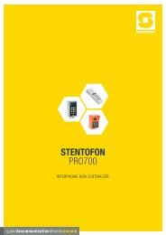
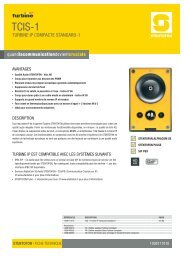
2.6.0 EQUIPMENT & PRODUCTS FOR ALPHACOM E SYSTEMA. STANDARD DESK MASTER. Master shall include the following controls: dialing buttons 0-9; Manual“M,” button for speech control and other functions; cancel “C” button; privacy slide switch and variablevolume control. Shall include 10 direct access buttons. Shall include a 3", 63 ohm, 1.6 watt speakerwith a sensitivity 88 dB, mounted in an acoustic baffle. Shall include an electret condensermicrophone with 100/300 mV output and sensitivity of -65 dB @1 kHz. Shall include a preamplifierwith a 600 ohm output impedance, and greater than 40 dB signal to noise ratio. Frequency responseof input and output shall be 300 to 10,000 Hz. Master shall be in a modern gray and black plastichousing, suitable for desk mounting, and have a six foot cord and plug. Shall be Stentofon #70362.B. DESK MASTER WITH HANDSET. Master shall include the following controls: dialing buttons 0-9;Manual “M,” button for speech control and other functions; cancel “C” button; privacy slide switch andvariable volume control. Shall include 10 direct access buttons. Shall include a 3", 63 ohm, 1.6 wattspeaker with a sensitivity 88 dB, mounted in an acoustic baffle. Shall include an electret condensermicrophone with 100/300 mV output and sensitivity of -65 dB @1 kHz. Shall include a preamplifierwith 600 ohm output impedance, and greater than 40 dB signal to noise ratio. Frequency response ofinput and output shall be 300 to 10,000 Hz. Master shall be in a modern gray and black plastichousing, suitable for desk mounting, and have a six foot cord and plug with addition of a lightweighthandset for confidential conversations. Color shall be black and gray. Shall be Stentofon #70342.70342C. WALL MOUNT STANDARD MASTER. Shall function exactly like a standard desk master but with allcontrols, speaker and microphone mounted on an extruded aluminum face plate, suitable for wallmounting. Shall include a sensitive condenser microphone and a 3" round, 63 ohm speaker with a 5ounce magnet. Finish shall be anodized aluminum. Mounts on #6020 flush or #6031 surface backbox.Shall be Stentofon #7040 and #7042 or #7045US.7040 7042 7045US<strong>Zenitel</strong> USA - 6119 Connecticut Avenue – Kansas City, MO 64120 – 816/231-7200 – Fax: 816/231-7203 – www.zenitelusa.com
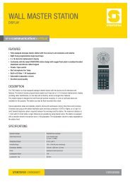
D. DESK DISPLAY MASTER. Master shall include a standard 0-9 keypad, manual “M” button, “C’cancel button, privacy/open slide switch, LED call placed indicator, variable volume control, (10)programmable direct access buttons and a 2 1/2" x 1/2", and a 16 character LCD alphanumericdisplay. Shall include a 3", 63 ohm 1.6 watt speaker with a 5 ounce magnet mounted in an acousticbaffle. Shall include an electric condenser microphone with a 100/300 mV output and sensitivity of -65dB @ 1 kHz. Shall include preamplifier with 1000 ohm output impedance and frequency range of 300to 10,000 Hz. Housing shall be ABS plastic finished suitable for desk or surface wall mounting.Dimension shall not exceed 3" H x 7" W x 7" D. Shall be Stentofon #7071 (Black).E. DISPLAY MASTER WITH HANDSET. Shall be identical to the 7071 Display Master, with addition of ahandset, coiled cord and magnetic hook-switch. Shall be Stentofon #7072 or #7070 (Black).7072 7070F. DUAL DISPLAY MASTER. Master shall include a 10 direct access keys (DAK) keypad, divided into 9pages with information text for each DAK on a 5-8 character display. The station dialing keys shallhave letters to be used for search facility in the intercom directory and display text editing. The stationshall have 4 specific navigation keys for quick access to system menus and directory entries. Statusinformation, guidance and menus are shown on a large 4 line graphic display. Frequency responseof input and output shall be 300 to 7,000 Hz. Housing shall be ABS plastic finished suitable for deskmounting. Dimension shall not exceed 2.8" H x 5.5" W x 10.6" D. Shall be Stentofon #7007 (Black).7007 with/without gooseneck<strong>Zenitel</strong> USA - 6119 Connecticut Avenue – Kansas City, MO 64120 – 816/231-7200 – Fax: 816/231-7203 – www.zenitelusa.com
G. CONTROL ROOM MASTER (CRM-IV). Compact desk top console master shall include a 3" speaker,condenser microphone with preamplifier and automatic sensitivity adjustment, handset with coiledcord, dial keypad with manual and cancel button, privacy switch, optional programmable directaccess buttons (modules of 48 buttons, with a maximum of two modules), (4) function buttons and a 4line 20 character alphanumeric, backlit LCD display. Shall allow up to (100) call requests in queuewith (256) priority levels, and allow multiple parallel masters with transfer of command. Shall operatewith only (3) pair twisted #22 gauge wire. Shall be Stentofon #7006102.H. CONTROL ROOM MASTER. This advanced control room master features a large 4 x 20 characteralphanumeric LCD display with backlight. This station shall have a full dialing keypad, 10programmable single touch keys, answer-next-in-queue key, handset, sensitive electret microphoneand a powerful 1W loudspeaker. The station shall have full loud speaking conversation withautomatic switching of the speech direction. This station shall be able to manually override theautomatic speech switching for a push-to-talk operation. Handset is optional order part # 92497(Desk) #92495 (Rack). Temperature Range: 0° C +40° C (+32° F to +104° F); Dimensions: 14” x 7” x3” (Desk) 5 ¼” x 19” (Rack); Finish: Black; Loudspeaker Output: 1 W (63 Ohm) Frequency Range:300-5,000 Hz. Shall operate with only (3) pair twisted #22 gauge wire. Shall be the Stentofon#7053R (Rack) or #7053D (Desk).7053R7053DI. STAINLESS STEEL SUBSTATION (OUTDOOR/INDOOR). Shall be a tamper resistant, electronicsubstation with one (1) stainless steel call request push button, a 2.5", 45 ohm speaker, an electretcondenser microphone with preamplifier mounted on a 11 gauge, #304 Stainless Steel face plate.The call button shall be programmed to call a specific master. The electronic board shall be encasedin epoxy and have built in transient suppression and plate shall include a rubberized gasket. Shallmount on a standard (2) gang deep electrical back box, box provided by others. 6291 series isn’trecommend for outdoor installations, but if installed outside installer must drill weep holes in backbox.Shall be Stentofon #6291 or #6291RM (Optional Red Call Button).6291 (6291RM - with red mushroom button)<strong>Zenitel</strong> USA - 6119 Connecticut Avenue – Kansas City, MO 64120 – 816/231-7200 – Fax: 816/231-7203 – www.zenitelusa.com
J. STAINLESS STEEL SUBSTATION (OUTDOOR/INDOOR). Shall be a tamper resistant, electronicsubstation with one (1) or two (2) stainless steel call request push button(2), a 2.5", 45 ohm speaker,an electret condenser microphone with preamplifier mounted on a 11 gauge, #304 Stainless Steelface plate. The call button shall be programmed to call a specific master. The electronic board shallbe encased in epoxy and have built in transient suppression and plate shall include a rubberizedgasket. Shall mount on a standard (3) gang deep electrical back box, box provided by others. 6294series isn’t recommend for outdoor installations, but if installed outside installer must drill weep holesin backbox. Shall be Stentofon #6294-1 or #6294-2. Optional #6294RM Red Call Button not shown.6294 (6294-2 with two button option)K. EXTERIOR TAMPER-RESISTANT SUBSTATION. This station shall be tamper resistant with one 1.5”red mushroom button. The station shall be mounted on a 1/4" thick aluminum plate designed towithstand extreme abuse. Moisture resistant speaker and microphone shall be mounted behind twooffset grills, milled into aluminum block to prevent damage from foreign material or water. Theelectronic board shall be encased in epoxy and have built in transient suppression and plate shallinclude a rubberized gasket. The station shall mount on a #6297 flush, #6298 surface or #62991 castweatherproof backbox. If installed outside, installer must drill weep holes in backbox. Shall beStentofon #62927. Available in dual button version #62922-7 top button (silver) bottom button (red).62927L. IP DESK MASTER STATION. Desk master station for use in offices and control rooms. Stationfeatures a large high contrast display with backlight which allows important information aboutconnections to be shown. The 80010 is equipped with 10 DAK keys that provide single touch accessto stations, group calls, etc and handset for confidential conversations. It connects directly to IPnetwork making it easy to deploy anywhere at any distance, and has an integrated web server foreasy configuration, monitoring and remote automatic software updates. Station provides widebandaudio. Connection must be to a PoE switch. Shall be Stentofon # 80010 IP Desk Master w/handset or#80000 IP Desk Master.80010 80000M. IP OR MASTER. Master station for use in operating and clean rooms that require chemical resistantand anti-bacterial front surface for easy cleaning. Station features a large high contrast display with<strong>Zenitel</strong> USA - 6119 Connecticut Avenue – Kansas City, MO 64120 – 816/231-7200 – Fax: 816/231-7203 – www.zenitelusa.com
acklight and up to 8 lines with 20 characters as well as the added feature of lighting behind each keythat provides excellent readability in locations where lighting can be a problem. Station connectsdirectly to IP network making it easy to deploy anywhere at any distance. Station has integrated webserver for easy configuration, monitoring and remote a automatic software updates are built infeatures. Station provides wideband audio and may be powered locally or connected to a POEswitch. Station can be mounted in flush 80987 backbox. Optional handset unit 80971 is available asan option. Shall be Stentofon 80150 IP OR Master.80150N. IP FLUSH MASTER. Flush master station with display is a general purpose intercom station Intendedfor use where a desktop station is impractical. Station features a large high contrast display withbacklight which allows important information about connections to be shown very clearly. Station isequipped with 4 DAK keys that provide single-touch access to stations and features. Station connectsdirectly to IP network making it easy to deploy anywhere at any distance. Station has integrated webserver for easy configuration, monitoring and remote automatic software updates are built in features.Station provides wideband audio and may be powered locally or connected to a POE switch. Stationcan be mounted in flush 80987 backbox. Optional handset unit 80971 is available as well as optionalgooseneck microphone 80975. Shall be Stentofon 80310 IP FLUSH MASTER80310<strong>Zenitel</strong> USA - 6119 Connecticut Avenue – Kansas City, MO 64120 – 816/231-7200 – Fax: 816/231-7203 – www.zenitelusa.com
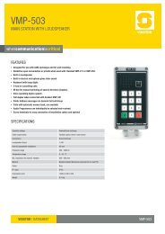
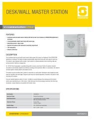
2.6.1 EQUIPMENT & PRODUCTS FOR <strong>9400</strong> SYSTEMA. 9401 – INTERCOM MODULE CARD RACK (IMCR). The Card cage fits into a standard 19-inchrack for easy installation. The rack provides space for a power supply module (9490), one modulecontroller board (9440) and a maximum of 10 intercom module line boards (9450). Each card cagehas the capacity for a maximum of 100 substations per module. All connections on the back planeof module are either removable screw terminal connections or 50 pin Amphenol connections. Therack’s clear front cover allows installers and technicians to check status of the system withoutremoving the cover.Dimensions: 19” W x 10.5” H x 10” D9401 Card RackB. 9490X – INTERCOM MODULE POWER SUPPLY (IMPS). This plug in power supply provides 5,12 & 24VDC for the control boards installed in the 9401 rack. Power supply module will work overa wide range of ac voltage input (85-264 VAC). Power supply has overload protection and statusLED’s for each voltage. The power supply module can be equipped with 0-2 (X=0-2) of the 9680amplifiers for use with substations that use 45-ohm speakers (i.e. 9600 series of substations).Mounting of the power supply is done by slide rail into the 9401 rack. One 9490X power supplymodule is required for each 9401 rack installed.Dimensions: 1.1875” W x 8.5” H x 9.4375” DC. 9440 – INTERCOM MODULE CONTROLLER BOARD (IMCB). The module controller boardprovides all module control functions for the <strong>9400</strong> system. It provides two audio channels that willallow two simultaneous conversations. All customer programming is stored in EEPROM andprogramming is completed from a PC using a terminal emulation program such as WindowsHyperTerminal or <strong>9400</strong> programming software located on the <strong>Zenitel</strong> CD sent with your <strong>9400</strong>. One9440 module controller board is required for each 9401 rack installed. Mounting is accomplishedby pushing board into back plane of 9401 rack.D. 9450 INTERCOM MODULE LINE BOARD (IMLB). The module line board supports up to 10substation positions per card. It provides the ability for 2-wire or 4-wire substations and has outputdrivers for LED’s for each 10 station ports on the line board. Up to two 9600 series substationsmay be connected to a single substation port with both stations having common audio and call in.Up to four 25V speaker substations can be connected to a single substation port with all fourstations having common audio and call in. The line board provides ability for 2 & 4 wire (LEDoption) 9600 series substations and also the ability for 2 wire 25V substations or 4 wire 25Vsubstations with call in capability. Maximum 10 IMLB boards may be installed into each 9401 rack.<strong>Zenitel</strong> USA - 6119 Connecticut Avenue – Kansas City, MO 64120 – 816/231-7200 – Fax: 816/231-7203 – www.zenitelusa.com
E. 9620 – TAMPER RESISTANT SUBSTATION. The 9620 mounts into a standard 3-gang deepelectrical back box with a depth of 2.5”. The 9620 requires one pair of wire for connection to the<strong>9400</strong> system. Optional LED may be added by ordering the 9620L; if 9620L is used a 2 pair of wireis needed for connection to the <strong>9400</strong> system. The 9620 can be equipped with a red call in buttonand provided in a weather-resistance version.9620 SubstationF. 9621 – TAMPER RESISTANT SUBSTATION. The 9621 mounts into a standard 2-gang deepelectrical back box with a depth of 2.5”. The 9621 requires 1 pair of wire for connection to the <strong>9400</strong>system. Optional LED may be added by ordering the 9621L; if 9621L is used then 2 pair of wire isneeded for connection to the <strong>9400</strong> system. 9621 can be equipped with red call in button andprovided in a weather-resistance version.9621 SubstationG. 96257 – WEATHER & TAMPER RESISTANT SUBSTATION. The 96257 mounts into a <strong>Zenitel</strong>back box for outdoor applications where the substation can be subjected to harsh weather. Thesubstation is equipped with WP speaker and the PC board is dipped in epoxy for outdoorapplications. Station is also equipped with a LED for ADA requirements and red shoulder/slambutton for call in. The 96257 station requires 2 pair of wire for installation.96257 Substation<strong>Zenitel</strong> USA - 6119 Connecticut Avenue – Kansas City, MO 64120 – 816/231-7200 – Fax: 816/231-7203 – www.zenitelusa.com
H. 96257-9 – SECURITY/EMERGENCY SUBSTATION. The 96257-9 mounts into 1600 seriesstanchions or 1040 series surface back boxes for installation in outdoor applications wheresubstation can be subjected to harsh weather. This substation is equipped with WP speaker, PCboard dipped in epoxy, red shoulder/slam call button and relay strobe board. Strobe relay board isused to control strobe light that is part of the 1600 series stanchion and if the strobe light is boughtas a standalone item. The 96257-9 station requires 2 pair of wire for installation. Local power isrequired for strobe and strobe relay at location of substation.96257-9 SubstationI. 9626 – CEILING SPEAKER SUBSTATION. The 9626 mounts into a ceiling back box and has thesame electrical functions as the 9620 but without a call button. Call button can be attached to 9626for call in if desired. 9626 station requires 1 pair of wire for installation.J. 9627 – ELEVATOR SUBSTATION UNIT. The 9627 mounts behind the elevator panel and has thesame electrical functions as the 9620 but without a call button. A call button can be attached to9627 for call in. The 9627 station requires 1 pair of wire for installation.9627 Elevator SubstationK. 9628 – SPEAKER SUBSTATION INTERFACE. The 9628 unit consists of a substation boardmounted inside a box. The unit has provisions for connection of a 45-ohm speaker and a call-inbutton via screw terminal connections. 9628 interface requires 1 pair of wire for installation.L. 96283 – SPEAKER INTERFACE. The 96283 is used for connection to existing speaker and callbutton in retrofit applications when there is not enough required space to mount a 9628 unit or9629 board. The 96283 provides connection for speaker only. Optional call button can be attachedto unit but additional resistor of 10K must be supplied.<strong>Zenitel</strong> USA - 6119 Connecticut Avenue – Kansas City, MO 64120 – 816/231-7200 – Fax: 816/231-7203 – www.zenitelusa.com
M. 9629 – SUBSTATION BOARD. The 9629 board is used for connection of a 45 ohm speaker andcall button to create a 9600 series substation. It’s also used for the 9620, 9621, 9626 and 9628units. This is a PC board the customer is responsible for mounting in suitable enclosure. The 9629board requires 1 pair of wire for installation.Note to specifier: Call buttons are normally open momentary close type. On/off buttons can beused on units that require call buttons however the button must be reset before the call is ended orupon cancellation of call the station will place a call.N. SUBSTATIONS – 25V TYPE. These substations are commercially available and are used forsecurity, correctional and school applications. Stations come in a variety of sizes with 25V speakerand with or without call buttons. If substation is not equipped with a call button, a single pair of wireis needed for installation. If substation is equipped with a call button, 2 pair of wire is needed forinstallation. If 25V substations are used then 25V amplifiers must be provided for outgoing audio.Note 1: <strong>Zenitel</strong> USA does not provide 25V substations.Note 2: Existing substations using a 45-ohm speaker with no termination and a separate callbutton can be connected to this module. In this case you need two pair of wire.O. 9457 – CONNECTION CABLE FOR LINE BOARDS. The 9457 connection cable kit is a 50 pinfemale Amphenol cable assembly. The kit connects to connectors on the back plane of the 9401for each 9450 line card slot. The 9457 kit is then mounted via standoffs on the back of the 9401rack for a neat installation of station cables. One 9457 connection cable kit is required per 9450line board used.P. 96580 – CABLE AND CONNECTOR. The 96580 cable and connector is equipped with a 50 pinmale Amphenol for connection to a 9457 and a cable length of 20 feet with bare wire at the otherend for punching down wire on a 96570 MDF block. One 96580 cable and connector is requiredper 9450-line board used.Q. 96570 – BASIC MDF. The 96570 basic MDF is a standard “66” telephone block used to punchdown wiring from the 96580 cable and wiring to/from the substations in the field. One 96570 isrequired per 9450 line board.R. SDR-114 – SOUND THRESHOLD BOARD. The SDR-114 board is used in conjunction with the9600 substations to place a call to the <strong>9400</strong> system when an audio disturbance above a certainsound level and duration occurs. The SDR-114 is housed in a SDR-D series card cage.S. SDR-D SERIES CARD CAGE RACK. The SDR-D series card cage rack is used for SDR-114boards. Each SDR-D series rack is capable of housing up to 25 boards in multiples of 5 boards ata time. 5, 10, 15, 20 and 25 card cage sizes are available.2.6.2 OPTIONS FOR ALPHACOM E (Available with additional equipment)A. MICROPHONE AMPLIFIER & RELAY (MADER). Shall provide amplified calling and two-waycommunication through separate loudspeaker, and preamplified audio input through either electretor dynamic microphone. Shall include relay control and adjustments for in/out volume. Shall beSTENTOFON #99601.<strong>Zenitel</strong> USA - 6119 Connecticut Avenue – Kansas City, MO 64120 – 816/231-7200 – Fax: 816/231-7203 – www.zenitelusa.com
B. STROBE CONTROL RELAY BOARD. Shall be mounted in security substations that have anassociated strobe light. Shall provide necessary contacts to turn on flashing strobe when intercomcall button is depressed. Strobe shall turn off when intercom conversation is canceled. Shall beSTENTOFON #9689-2.C. REMOTE IN/OUT CONTROL (RIO). Electronic board shall be included where ancillary devicesneed to be operated through relay contacts from the intercom system (outputs), and/or externalalarm conditions need to be displayed as text or voice message on LCD intercom masters.Devices such as bells, lights, CCTV cameras, electric door releases and amplifiers and otherdevices may be turned “on” or “off” by actions created by programming. Unit shall be equippedwith 8 contact inputs (Standard) and up to 18 contact outputs (When equipped with optional 99702Relay Board (6 contacts per board). It shall be possible to have multiple outputs per station. Shallbe STENTOFON #99705.D. STORED VOICE MESSAGES. System shall allow digitally stored voice messages to beautomatically transmitted to selected stations, or all stations within AlphaCom E. Shall bemicroprocessor controlled to store up to 60 minutes of speech messages, and allow simultaneousplay back of up to 8 messages. Shall include (9) pre-recorded voice help, (9) absence and (3)alarm messages standard to selected stations. Shall provide call request verification to initiator ofthe call. The prerecorded voice messages shall be natural sounding, high quality with 16 KHzsampling rate. A Call Acknowledge message to elevator car substations shall meet A.D.Arequirements. Customized alarm messages shall be available from the manufacturer. Messageboard shall be STENTOFON #9304 AVSP.E. AUTOMATIC SOUND DETECTION ALARM BOARD. The system shall include the necessarynumber of sound detection relay boards to monitor the audio level in areas such as elevators,selected stairwells and some areas of the parking garage. Each intercom substation that ismonitored shall be connected to an individual detection board. Each board shall include (6)controls for manual adjustments of ambient conditions in each area. Each board shall also allowautomatic compensation for changes to ambient conditions over a specific time period. Dynamicrange shall be over 40 dB, with timing adjustments from 1 - 33 seconds. BOARD. Shall beSTENTOFON #SDR-115 mounted in card cage.Note to specifier: indicate which stations require sound detectionF. VOICE RECORDER BOARD. System shall include a (6) circuit electronic buffer board with 600ohm output to match audio recording machines. Shall provide interface to record conversations ofsix different pairs of intercom stations. Shall mount on back of exchange. Shall be STENTOFON#1082-C VRB UNIT.G. ATLB TELEPHONE LINE BOARD. This board shall provide the ability to connect standard DTMFtelephones to AlphaCom to act as stations. The board provides 12 telephone connections and 1voice-switched speech channel. The board also provide 6 remote control outputs signals (RCO’s).Each telephone connects to ATLB board with standard 2-wire connection. Any station connectedto the telephone board can be included in an open duplex conference. Shall be STENTOFON#9104.H. FIBER COUPLER MODULES. These boards shall allow any 4-wire intercom station, master orsubstation to be connected to AlphaCom exchange using 2 multi-mode fibers per station. Thefiber modules will support LCD and non-LCD master stations along with substations. Fibermodules shall be wall or rack mounted. Shall be STENTOFON #92860M (Exchange Module) and#92860F (Field Module).<strong>Zenitel</strong> USA - 6119 Connecticut Avenue – Kansas City, MO 64120 – 816/231-7200 – Fax: 816/231-7203 – www.zenitelusa.com
PART III: EXECUTION3.1 INSTALLATIONA. Shall be installed by qualified technicians who have been factory trained and certified.B. Wiring shall be uniform and in accordance with national electric codes and manufacturersinstructions.C. Equipment shall be firmly secured, plumb, and level.D. All splices shall be in easily accessible junction boxes or on terminal boards.E. All cable runs at the main terminal board and in all junction boxes shall be tagged and identified.F. Coordinate all work with other effected trades and contractors.3.2 SYSTEM INITIALIZING AND PROGRAMMINGA. System shall include all software necessary for system configuration.B. System shall be turned on and adjustments made to meet requirements of specifications and onsiteconditions.C. System shall be programmed to function as specified.D. Directory numbers, feature codes, and special programming shall be documented, printed andmade available to owner.3.3 SYSTEM TEST PROCEDURESA. System shall be completely tested to assure that the exchange and all components, stations,speakers, and accessories are hooked-up and in working order.B. System shall be pre-tested by contractor and certified to function in accordance with plans andspecifications.C. System shall be tested in presence of owner's representative.3.4 OWNER INSTRUCTIONSA. Installation contractor shall conduct up to (4) hours of instruction in use and operation of thesystem to designated owner representatives, within (30) days of system acceptance. Owner willprint and distribute directory number plan to users.B. Installation contractor shall conduct up to (4) hours of technical training, in programming,troubleshooting, and service of the system, to designated owner representatives within (90) daysof system acceptance.C. Manufacturer shall conduct periodic (every 90 days) technical training seminars and make themavailable to those responsible for on-going maintenance of the system.<strong>Zenitel</strong> USA - 6119 Connecticut Avenue – Kansas City, MO 64120 – 816/231-7200 – Fax: 816/231-7203 – www.zenitelusa.com
3.5 ON-SITE SPARESA. The following items shall be included in the system package and turned over to owner within (30)days of system acceptance.1. (1) Central exchange spare parts kit.2. (1) Desk master Station.3. (1) Tamper resistant security substation.3.6 MANUALS AND DRAWINGS(Note to specifier: Indicate exact items required)A. Contractor shall provide owner with (2) copies of standard factory prepared operation, installationand maintenance manuals. Manuals shall include typical wiring diagrams.B. Contractor shall provide owner with (2) copies of any risers, layouts, and special wiring diagramsshowing any changes to standard drawings, if required on project.<strong>Zenitel</strong> USA - 6119 Connecticut Avenue – Kansas City, MO 64120 – 816/231-7200 – Fax: 816/231-7203 – www.zenitelusa.com