

Frame Relay - for Faster and More Efficient Data Communications ...
Frame Relay - for Faster and More Efficient Data Communications ...
Frame Relay - for Faster and More Efficient Data Communications ...
- No tags were found...

You also want an ePaper? Increase the reach of your titles
YUMPU automatically turns print PDFs into web optimized ePapers that Google loves.
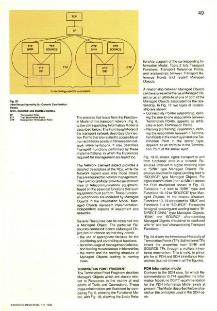
49TERMINATION POINT FRAGMENTThe Termination Point Fragment decribesManaged Objects which are closely relatedto Resources in the vicinity of endpoints of Trails <strong>and</strong> Connections. Theseclose relationships are illustrated by comparingFig. 6, showing the Functional Model,with Fig. 18, showing the Entity Relationshipdiagram of the corresponding In<strong>for</strong>mationModel. Table 2 lists TransportFunctions, Transport Reference Points,<strong>and</strong> relationships between Transport ReferencePoints <strong>and</strong> related ManagedObjects.Fig. 20Inheritance Hierarchy <strong>for</strong> Generic TerminationPointsSINK, SOURCE <strong>and</strong> BIDIRECTIONALTPTTPCTPTermination PointTrail Termination PointConnection Termination PointThe process that leads from the FunctionalModel of the transport network, Fig. 6,to the corresponding In<strong>for</strong>mation Model isdescribed below. The Functional Model ofthe transport network describes ConnectionPoints that are related to accessible ornon-accessible points in transmission networkimplementations. It also describesTransport Functions per<strong>for</strong>med by theseimplementations, in which the Resourcesrequired <strong>for</strong> management are found too.The Network Element aspect provides adetailed description of the NEs, while theNetwork aspect uses only those detailsthat are required <strong>for</strong> network management.The Functional Model provides an abstractview of telecommunications equipment,based on the essential functions that suchequipment must per<strong>for</strong>m. These functionalcomponents are modelled by ManagedObjects in the In<strong>for</strong>mation Model. ManagedObjects represent implementationindependentaspects of equipment <strong>and</strong>networks.Several Resources can be combined intoa Managed Object. The particular Resourcescombined to <strong>for</strong>m a Managed Objectcan be chosen so that they permit- the use of appropriate facilities <strong>for</strong> themonitoring <strong>and</strong> controlling of functions- iterative usage of management in<strong>for</strong>mationleading to subclasses in hierarchies-the name <strong>and</strong> the naming structure ofManaged Objects leading to namingtrees.A relationship between Managed Objectscan be expressed either as a Managed Objector as an attribute of one or both of theManaged Objects associated by the relationship.In Fig. 18 two types of relationshipare shown:- Connectivity Pointer relationship, definingthe one-to-one association betweenTermination Points, appears as attributesin both Termination Points- Naming (containing) relationship, definingthe association between n TerminationPoints in the client layer <strong>and</strong> one TerminationPoint in the server layer,appears as an attribute in the TerminationPoint of the server layer.Fig. 19 illustrates signal transport to <strong>and</strong>from functional units in a network. Resourcesinvolved in signal receiving leadto "SINK" type Managed Objects. Resourcesinvolved in signal sending lead to"SOURCE" type Managed Objects. Forsignal transmission 2 to 140 Mbit/s acrossthe PDH multiplexer shown in Fig. 13,Functions 1-4 lead to "SINK" type <strong>and</strong>Functions 10-19 to "SOURCE" type ManagedObjects. In the reverse direction,Functions 10-19 are related to "SINK" <strong>and</strong>Functions 1-4 to "SOURCE". Resources<strong>for</strong> signal receiving <strong>and</strong> sending lead to "BIDIRECTIONAL" type Managed Objects."SINK" <strong>and</strong> "SOURCE" characterisingManaged Objects should not be confusedwith "in" <strong>and</strong> "out" characterising TransportFunctions.Fig. 20 shows the Inheritance Hierarchy ofTermination Points (TP). Bidirectional TPsinherit the properties from SINK <strong>and</strong>SOURCE TPs through a multiple inheritancemechanism. This is valid, in principle,<strong>for</strong> all PDH <strong>and</strong> SDH Inheritance Hierarchies(but not shown in all the figures).PDH In<strong>for</strong>mation modelContrary to the SDH case, <strong>for</strong> which RecommendationG.774 specifies the In<strong>for</strong>mationModel, no CCITT recommendation<strong>for</strong> the PDH In<strong>for</strong>mation Model exists atpresent. The Model described below is basedon the principles used in the SDH case.ERICSSON REVIEW No. 1-2, 1992


