VLMpc Manual - the AOE home page
VLMpc Manual - the AOE home page
VLMpc Manual - the AOE home page
- No tags were found...
You also want an ePaper? Increase the reach of your titles
YUMPU automatically turns print PDFs into web optimized ePapers that Google loves.
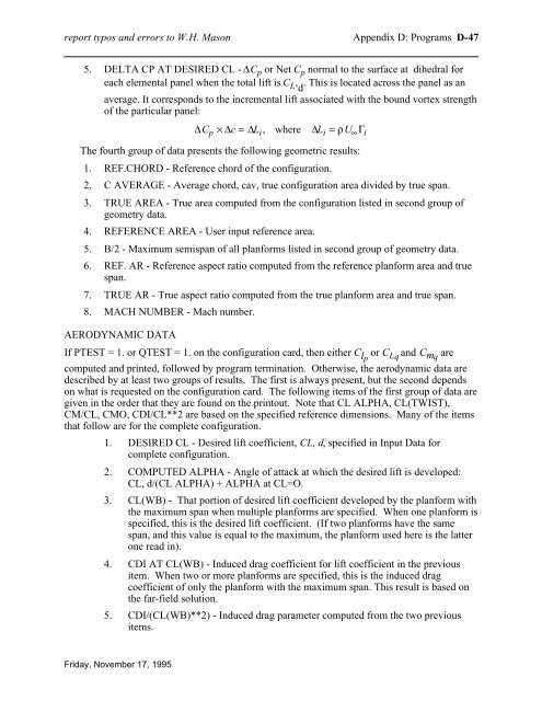
eport typos and errors to W.H. Mason Appendix D: Programs D-475. DELTA CP AT DESIRED CL - ∆C p or Net C p normal to <strong>the</strong> surface at dihedral foreach elemental panel when <strong>the</strong> total lift is C L , d. This is located across <strong>the</strong> panel as anaverage. It corresponds to <strong>the</strong> incremental lift associated with <strong>the</strong> bound vortex strengthof <strong>the</strong> particular panel:The fourth group of data presents <strong>the</strong> following geometric results:1. REF.CHORD - Reference chord of <strong>the</strong> configuration.2. C AVERAGE - Average chord, cav, true configuration area divided by true span.3. TRUE AREA - True area computed from <strong>the</strong> configuration listed in second group ofgeometry data.4. REFERENCE AREA - User input reference area.5. B/2 - Maximum semispan of all planforms listed in second group of geometry data.6. REF. AR - Reference aspect ratio computed from <strong>the</strong> reference planform area and truespan.7. TRUE AR - True aspect ratio computed from <strong>the</strong> true planform area and true span.8. MACH NUMBER - Mach number.AERODYNAMIC DATA∆C p × ∆c = ∆L i , where ∆L i = ρU ∞ Γ iIf PTEST = 1. or QTEST = 1. on <strong>the</strong> configuration card, <strong>the</strong>n ei<strong>the</strong>r C lp or C L q and C mq arecomputed and printed, followed by program termination. O<strong>the</strong>rwise, <strong>the</strong> aerodynamic data aredescribed by at least two groups of results. The first is always present, but <strong>the</strong> second dependson what is requested on <strong>the</strong> configuration card. The following items of <strong>the</strong> first group of data aregiven in <strong>the</strong> order that <strong>the</strong>y are found on <strong>the</strong> printout. Note that CL ALPHA, CL(TWIST),CM/CL, CMO, CDI/CL**2 are based on <strong>the</strong> specified reference dimensions. Many of <strong>the</strong> itemsthat follow are for <strong>the</strong> complete configuration.1. DESIRED CL - Desired lift coefficient, CL, d, specified in Input Data forcomplete configuration.2. COMPUTED ALPHA - Angle of attack at which <strong>the</strong> desired lift is developed:CL, d/(CL ALPHA) + ALPHA at CL=O.3. CL(WB) - That portion of desired lift coefficient developed by <strong>the</strong> planform with<strong>the</strong> maximum span when multiple planforms are specified. When one planform isspecified, this is <strong>the</strong> desired lift coefficient. (If two planforms have <strong>the</strong> samespan, and this value is equal to <strong>the</strong> maximum, <strong>the</strong> planform used here is <strong>the</strong> latterone read in).4. CDI AT CL(WB) - Induced drag coefficient for lift coefficient in <strong>the</strong> previousitem. When two or more planforms are specified, this is <strong>the</strong> induced dragcoefficient of only <strong>the</strong> planform with <strong>the</strong> maximum span. This result is based on<strong>the</strong> far-field solution.5. CDI/(CL(WB)**2) - Induced drag parameter computed from <strong>the</strong> two previousitems.Friday, November 17, 1995


