

Structural Design and Response in Collision and Grounding
Structural Design and Response in Collision and Grounding
Structural Design and Response in Collision and Grounding

You also want an ePaper? Increase the reach of your titles
YUMPU automatically turns print PDFs into web optimized ePapers that Google loves.
Brown, A.J., Tikka, K., Daidola, J., Lutzen, M., Choe, I., "<strong>Structural</strong> <strong>Design</strong> <strong>and</strong> <strong>Response</strong> <strong>in</strong> <strong>Collision</strong> <strong>and</strong> Ground<strong>in</strong>g", SNAME Transactions 108, pp.447-473, 2000.<strong>Structural</strong> <strong>Design</strong> <strong>and</strong> <strong>Response</strong> <strong>in</strong> <strong>Collision</strong> <strong>and</strong> Ground<strong>in</strong>gAlan Brown, Member, Virg<strong>in</strong>ia Tech, Kirsi Tikka, Member, Webb Institute, John C. Daidola,Fellow, AMSEC LLC, Marie Lützen, Student Member, Technical University of Denmark, Ick-Hung Choe, Student, Pusan National UniversityAbstractThe results summarized <strong>in</strong> this paper represent the work of SNAME Ad Hoc Panel #6 convened underthe SNAME Technical <strong>and</strong> Research Program. This is a summary <strong>and</strong> overview paper. Topicsdiscussed will be addressed <strong>in</strong>dividually <strong>and</strong> <strong>in</strong> more detail <strong>in</strong> later publications. The 2ndInternational Conference on <strong>Collision</strong> <strong>and</strong> Ground<strong>in</strong>g of Ships, to be held <strong>in</strong> Copenhagen, July 1-3,2001, will also present <strong>and</strong> discuss many of the results of this panel <strong>and</strong> other related research. Thepaper discusses four primary areas of panel work: collision <strong>and</strong> ground<strong>in</strong>g models, data, accidentscenarios <strong>and</strong> design applications. A probabilistic framework for assess<strong>in</strong>g the crashworth<strong>in</strong>ess ofships is presented. Results obta<strong>in</strong>ed from various ground<strong>in</strong>g <strong>and</strong> collision models are compared tovalidat<strong>in</strong>g cases <strong>and</strong> to each other. Data necessary for proper model validation <strong>and</strong> probabilisticaccident scenario development are identified. Deformable strik<strong>in</strong>g-ship bow models <strong>and</strong> theirapplication are described. Potential design applications <strong>and</strong> alternatives for improv<strong>in</strong>gcrashworth<strong>in</strong>ess are discussed.1 INTRODUCTIONOn May 14, 1998, SNAME Ad Hoc Panel #6, <strong>Structural</strong><strong>Design</strong> <strong>and</strong> <strong>Response</strong> <strong>in</strong> <strong>Collision</strong> <strong>and</strong> Ground<strong>in</strong>g, wasformed under the SNAME T&R Steer<strong>in</strong>g Committee withsupport from the Hull Structure Committee, Ship <strong>Design</strong>Committee <strong>and</strong> Mar<strong>in</strong>e Safety <strong>and</strong> EnvironmentalProtection Panel (O-44). The objectives of the panel are:• Investigate, compare <strong>and</strong> assess tools for predict<strong>in</strong>gground<strong>in</strong>g <strong>and</strong> collision damage (<strong>in</strong>clud<strong>in</strong>g collisionwith ice). Emphasize simplified methods, which canbe readily applied to the design <strong>and</strong> rapid analysis ofnew structural concepts, <strong>in</strong>clud<strong>in</strong>g applications us<strong>in</strong>gprobabilistic scenarios. F<strong>in</strong>ite element <strong>and</strong> othermore rigorous methods may be considered <strong>and</strong> usedto validate simplified methods. Include comparisonsto available data.• Propose a format for a collision <strong>and</strong> ground<strong>in</strong>gdatabase. The database may <strong>in</strong>clude actual,experimental <strong>and</strong> simulated data as long as it isproperly identified. Gather <strong>in</strong>itial data.• Def<strong>in</strong>e st<strong>and</strong>ard scenarios <strong>and</strong> conditions forground<strong>in</strong>g <strong>and</strong> collision analyses. This may <strong>in</strong>cludeprobabilistic <strong>and</strong>/or determ<strong>in</strong>istic descriptions of shipspeed, trim, collision angle, strik<strong>in</strong>g shipdisplacement, strik<strong>in</strong>g ship bow characteristics,impact po<strong>in</strong>t, bottom, rock characteristics, rockheight above basel<strong>in</strong>e, sea state, ice mass, etc.• Def<strong>in</strong>e st<strong>and</strong>ard criteria <strong>and</strong> methodologies forapply<strong>in</strong>g structural performance <strong>in</strong> ground<strong>in</strong>g <strong>and</strong>collision <strong>in</strong>clud<strong>in</strong>g oil outflow, carriage of nuclearwaste, damaged stability, ultimate strength <strong>and</strong>serviceability. Provide a basis for performancespecifications <strong>in</strong> these areas.• As tools, st<strong>and</strong>ard scenarios, methodologies <strong>and</strong>performance criteria are evaluated <strong>and</strong> def<strong>in</strong>ed, applythem to a matrix of typical <strong>and</strong> <strong>in</strong>novative structuraldesigns <strong>and</strong> concepts. Identify promis<strong>in</strong>g conceptsfor future study.This paper is a summary report of work performed bythe panel. It is the first of the deliverables specified <strong>in</strong> thepanel’s charter. Additional papers <strong>and</strong> reports willfollow. The panel has three work<strong>in</strong>g groups study<strong>in</strong>g: 1)tools for predict<strong>in</strong>g damage <strong>in</strong> ground<strong>in</strong>g <strong>and</strong> collision; 2)collision <strong>and</strong> ground<strong>in</strong>g scenarios; <strong>and</strong> 3) <strong>in</strong>novativedesign concepts. Funded research is centered at Virg<strong>in</strong>iaTech <strong>and</strong> Webb Institute.The work of the panel, as presented <strong>in</strong> this paper,consists of four essential elements:• Benchmark<strong>in</strong>g of ground<strong>in</strong>g modelsOther Members of the Ad Hoc Panel contribut<strong>in</strong>g to this paper are:Donghui Chen Jeom Paik Bo Simonsen Surya Vakkalanka Ge Wang Rong Huang Rick van HemmenJohn Sajdak Arne Stenseng Brett Fox Ryszard Kaczmarek Peter Good<strong>in</strong>g
• Benchmark<strong>in</strong>g <strong>and</strong> development of collisionmodels• Def<strong>in</strong>ition of ground<strong>in</strong>g <strong>and</strong> collision scenarios<strong>in</strong>clud<strong>in</strong>g strik<strong>in</strong>g bow geometry <strong>and</strong> bowstiffness.• Innovative design concepts2 MOTIVATIONThe serious consequences of ship ground<strong>in</strong>g <strong>and</strong> collisionnecessitate the development of regulations <strong>and</strong>requirements for the subdivision <strong>and</strong> structural design ofships to reduce damage <strong>and</strong> environmental pollution, <strong>and</strong>improve safety.The International Maritime Organization (IMO) isresponsible for regulat<strong>in</strong>g the design of oil tankers <strong>and</strong>other ships to provide for ship safety <strong>and</strong> environmentalprotection. Their ongo<strong>in</strong>g transition to probabilisticperformance-based st<strong>and</strong>ards requires the ability topredict the environmental performance <strong>and</strong> safety ofspecific ship designs. This is a difficult problemrequir<strong>in</strong>g the application of fundamental eng<strong>in</strong>eer<strong>in</strong>gpr<strong>in</strong>ciples <strong>and</strong> risk analysis.IMO first <strong>in</strong>troduced probabilistic st<strong>and</strong>ards <strong>in</strong>damage stability regulations for passenger ships [1] <strong>and</strong>later for cargo ships [2]. IMO’s first attempt to apply aprobabilistic methodology to tankers was <strong>in</strong> response tothe US Oil Pollution Act of 1990 (OPA 90). In OPA 90the US required that all oil tankers enter<strong>in</strong>g US watersmust have double hulls. IMO responded to this unilateralaction by requir<strong>in</strong>g double hulls or their equivalent.Equivalency is determ<strong>in</strong>ed based on probabilistic oiloutflow calculations specified <strong>in</strong> the "Interim Guidel<strong>in</strong>esfor the Approval of Alternative Methods of <strong>Design</strong> <strong>and</strong>Construction of Oil Tankers Under Regulation 13F(5) ofAnnex I of MARPOL 73/78” [3], hereunder referred to asthe Interim Guidel<strong>in</strong>es.All of these regulations use probability densityfunctions (pdfs) to des cribe the location, extent <strong>and</strong>penetration of side <strong>and</strong> bottom damage. These pdfs arederived from limited historical damage statistics [4], <strong>and</strong>applied identically to all ships without consideration oftheir structural design. Figure 1 is the IMO probabilitydensity function used to def<strong>in</strong>e the longitud<strong>in</strong>al extent ofbottom damage from ground<strong>in</strong>g <strong>in</strong> oil outflowcalculations. The histograms represent the statistical datacollected by the classification societies <strong>and</strong> the l<strong>in</strong>ear plotrepresents IMO's piece-wis e l<strong>in</strong>ear fit of the data. OtherIMO pdfs are constructed <strong>in</strong> a similar manner.Probability Densityfb25.04.03.02.01.00.04.5LONGITUDINAL EXTENT FOR BOTTOM DAMAGE0.50.0 0.1 0.2 0.3 0.4 0.5 0.6 0.7 0.8Damage Length/Ship LengthTanker Data - 63 CasesPiecewise L<strong>in</strong>ear FitFigure 1 - Damage Probability Density Function [4]A major shortcom<strong>in</strong>g <strong>in</strong> IMO’s current oiloutflow <strong>and</strong> damage stability calculationmethodologies is that they do not consider the effect ofstructural design or crash-worth<strong>in</strong>ess on damageextent [5,6]. The primary reason for this exclusion isthat no def<strong>in</strong>itive theory or data exists to def<strong>in</strong>e thisrelationship.Other deficiencies <strong>in</strong>clude:• Damage pdfs consider only damage significantenough to breach the outer hull. This penalizesstructures able to resist rupture.• Damage extents are treated as <strong>in</strong>dependent r<strong>and</strong>omvariables when they are actually dependent variables,<strong>and</strong> ideally should be described us<strong>in</strong>g jo<strong>in</strong>t pdfs.• Damage pdfs are normalized with respect to shiplength, breadth <strong>and</strong> depth when damage may dependto a large extent on local structural features <strong>and</strong>scantl<strong>in</strong>gs vice global ship dimensions.It is logical <strong>and</strong> essential that crashworth<strong>in</strong>ess isconsidered <strong>in</strong> oil outflow <strong>and</strong> damage stabilitycalculations. An analytical method is required todef<strong>in</strong>e the relationship between structural design <strong>and</strong>damage extent <strong>in</strong> collision <strong>and</strong> ground<strong>in</strong>g. This is aprimary objective of the work of this panel.A method that considers crashworth<strong>in</strong>ess must besensitive to at least the basic parameters def<strong>in</strong><strong>in</strong>g uniquestructural designs while ma<strong>in</strong>ta<strong>in</strong><strong>in</strong>g sufficient generality<strong>and</strong> simplicity to be applied by work<strong>in</strong>g eng<strong>in</strong>eers <strong>in</strong> aregulatory context for a ship <strong>in</strong> worldwide operation. Itshould not require detailed f<strong>in</strong>ite element analysis or belimited to a s<strong>in</strong>gle accident scenario.An additional advantage of performance-basedmodels is the potential for their application todifferent <strong>and</strong> <strong>in</strong>novative designs. This is a secondprimary objective of this panel.0.52
3 PROBABILISTIC FRAMEWORKFigure 2 illustrates the process proposed to predict theprobabilistic extent of damage <strong>in</strong> collision as a function ofship structural design [7]. A similar process is proposedfor ground<strong>in</strong>g.Probability given collisionPo<strong>in</strong>t puncture, rak<strong>in</strong>g puncture,penetrat<strong>in</strong>g collisionPdf's:Strik<strong>in</strong>g ship speedStrik<strong>in</strong>g ship displacementStrik<strong>in</strong>g ship draft & bow heightStrik<strong>in</strong>g ship bow shape <strong>and</strong> stiffness<strong>Collision</strong> strik<strong>in</strong>g location & angleStruck ship design variables:Type (SH,DH,IOTD,DS,DB,DS)LBP, B, DSpeed & displacementSubdivision<strong>Structural</strong> designMonte CarloSimulationSpecificcollisionscenario'sPdf parametrics for extentof damage as a functionof struck ship designExtent ofDamageCalculationRegressionanalysisjo<strong>in</strong>t pdf forlongitud<strong>in</strong>al, vertical <strong>and</strong>transverse extent ofdamage:Figure 2 - Process to Predict Probabilistic Damage [7]The process beg<strong>in</strong>s with a set of probability densityfunctions (pdfs) def<strong>in</strong><strong>in</strong>g possible ground<strong>in</strong>g or collisionscenarios. Us<strong>in</strong>g these pdfs, a specific scenario isselected <strong>in</strong> a Monte Carlo simulation, <strong>and</strong> comb<strong>in</strong>ed witha specific ship structural design to predict damage. Thisprocess is repeated for thous<strong>and</strong>s of scenarios <strong>and</strong> a rangeof structural designs until sufficient data is generated tobuild a set of parametric equations relat<strong>in</strong>g probabilisticdamage extent to structural design. These parametricequations can then be used <strong>in</strong> oil outflow or damagestability calculations.1210864204.5Bottom Damage Longitud<strong>in</strong>al Extent PDF0.5DAMAGE Generated Po<strong>in</strong>tsMARPOL St<strong>and</strong>ard-20 0.2 0.4 0.6 0.8 1Length of Damage / Ship LengthFigure 3 – Bottom Damage pdf [6]0.5A damage pdf generated <strong>in</strong> an early application ofthis approach is shown <strong>in</strong> Figure 3 [6]. This pdf wasgenerated for a MARPOL s<strong>in</strong>gle hull tanker typical of thestruck ships represented <strong>in</strong> the data used to develop thecurrent MARPOL damage pdfs.4 GROUNDING MODELS4.1 Background <strong>and</strong> PlanThe Exxon Valdez accident <strong>in</strong> 1989 <strong>and</strong> the regulatoryevents follow<strong>in</strong>g it lead to active research on structuralbehavior <strong>in</strong> ground<strong>in</strong>g. The earlier studies had beenmostly empirical, the best-known be<strong>in</strong>g a study by Card[8] who surveyed 30 ground<strong>in</strong>g <strong>in</strong>cidents to determ<strong>in</strong>e theeffectiveness of a double bottom <strong>in</strong> reduc<strong>in</strong>g pollution.More recent studies have <strong>in</strong>cluded large numericalsimulations, small <strong>and</strong> large scale experiments, <strong>and</strong> thedevelopment of simplified methods. Many of thesestudies were supported by the project “Protection of OilSpills from Crude Oil Tankers” carried out by theJapanese Association for the <strong>Structural</strong> Improvement ofShipbuild<strong>in</strong>g Industry (ASIS). In the United States, theCarderock Division of the Naval Surface Warfare Center(NSWCCD) conducted ground<strong>in</strong>g experiments, <strong>and</strong> theMIT-Jo<strong>in</strong>t Industry Project on Tanker Safety developedsoftware to analyze structural damage <strong>in</strong> ground<strong>in</strong>g.Development of analytical models for the software wassupported by experimental studies. Active research efforton ground<strong>in</strong>g analysis has been carried out also <strong>in</strong>Europe, ma<strong>in</strong>ly <strong>in</strong> Denmark <strong>and</strong> the Netherl<strong>and</strong>s.The Specialist Panel V.4 of the 1997 InternationalShip <strong>and</strong> Offshore Structures Congress (ISSC 1997) [9]reviewed the state-of-the-art of the research <strong>and</strong>concluded that nonl<strong>in</strong>ear f<strong>in</strong>ite element analysis coupledwith calculation of ship motions had reached a level atwhich a fairly accurate prediction of the structuralresponse was possible. However, the report noted thats<strong>in</strong>ce the method is time consum<strong>in</strong>g <strong>and</strong> requires a highlevelof expertise, it is not suitable for the design orregulatory environment. The report also concluded thatthe simplified methods that existed at the time requiredfurther validation.This study concentrates on evaluation of the exist<strong>in</strong>gsimplified methods, which have been further developeds<strong>in</strong>ce the ISSC 1997 report. The objective is to assesstheir suitability for design <strong>and</strong> regulatory work.4.2 Models Included <strong>in</strong> the Current StudyThe methods evaluated <strong>in</strong> this study <strong>in</strong>clude DAMAGE, asoftware tool developed by the MIT-Jo<strong>in</strong>t Industry Projecton Tanker Safety, <strong>and</strong> a simple analytical methoddeveloped by Dr. Wang at the University of Tokyo(method by Wang). Both methods calculate ground<strong>in</strong>g3
force <strong>and</strong> extent us<strong>in</strong>g closed-form solutions, but theydiffer <strong>in</strong> the detail <strong>in</strong> which the structure is def<strong>in</strong>ed <strong>and</strong> itsbehavior is analyzed. The methods also differ <strong>in</strong> theirtreatment of ship motions. The program DAMAGE wasselected for further test<strong>in</strong>g <strong>and</strong> analysis, because it isapplicable for a wider range of ground<strong>in</strong>g scenarios.4.2.1 DAMAGE [10]The computer program DAMAGE was developed at MITunder the Jo<strong>in</strong>t MIT-Industry Program on Tanker Safety.This project, lead by Professor Tomasz Wierzbicki, was<strong>in</strong>itiated <strong>in</strong> 1991, <strong>and</strong> <strong>in</strong> addition to the programDAMAGE the project has produced more than 70technical reports about prediction of ground<strong>in</strong>g <strong>and</strong>collision damage. The program DAMAGE Version 5.0can be used to predict structural damage <strong>in</strong> the follow<strong>in</strong>gaccident scenarios:• Ship ground<strong>in</strong>g on a conical rock with arounded tip (rigid rock, deformable bottom)• Ship-ship collision (deformable side,deformable bow)Compared to previous models for prediction of ground<strong>in</strong>g<strong>and</strong> collision damage, a major advantage of DAMAGE isthat the theoretical models are hidden beh<strong>in</strong>d a moderngraphical user <strong>in</strong>terface (GUI) [10]. The program hasbeen developed with the objective of mak<strong>in</strong>g crashanalysis of ship structures feasible for eng<strong>in</strong>eers that donot have any particular experience <strong>in</strong> the field ofcrashworth<strong>in</strong>ess. Figure 4 shows the <strong>in</strong>put screen fordef<strong>in</strong><strong>in</strong>g the “ship-ground <strong>in</strong>teraction”, the relativeposition <strong>and</strong> velocity of ship <strong>and</strong> ground, coefficient offriction, etc.event, the contact force between ship <strong>and</strong> ground <strong>in</strong>ducesheave, roll <strong>and</strong> pitch motion on the ship, <strong>and</strong> eventuallycauses the ship to stop.The primary mechanisms of energy dissipation are:1. A change <strong>in</strong> potential energy of the ship <strong>and</strong> thesurround<strong>in</strong>g water as the ship is lifted by theground reaction.2. Friction between the ground <strong>and</strong> hull.3. Deformation <strong>and</strong> fracture of the hull.S<strong>in</strong>ce the lift<strong>in</strong>g of the ship off the rock generally causes areduction <strong>in</strong> crush<strong>in</strong>g <strong>and</strong> tear<strong>in</strong>g forces it is important to<strong>in</strong>clude the coupl<strong>in</strong>g between the global ship motions(external dynamics) <strong>and</strong> the local damage process(<strong>in</strong>ternal mechanics). Detailed descriptions of the modelfor the external dynamics can be found <strong>in</strong> References [11]<strong>and</strong> [12].For the model to be applicable to optimization forstructural crashworth<strong>in</strong>ess it is important that it capturesthe effect of :• Material strength <strong>and</strong> ductility• Dimensions <strong>and</strong> arrangement of major structuralcomponents such as bulkheads, decks, girders<strong>and</strong> large stiffeners.The theoretical model is based on a set of super-elementsolutions, i.e. closed form, analytical solutions for theenergy absorption of rather large structural componentsundergo<strong>in</strong>g large deformations. All structural componentsare assumed to follow the same overall mode ofdeformation around the rock. This way it is possible totake <strong>in</strong>to account the structural resistance of all typicalmembers <strong>in</strong> a ship bottom. The fracture criterion is basedon analytical solutions for plastic response of amembrane. Figure 5 shows a w<strong>in</strong>dow from an animationof the ship motion over the rock.A description of the procedure <strong>in</strong>clud<strong>in</strong>g detailedderivations of the super-element solutions can be found <strong>in</strong>References [13] <strong>and</strong> [14].Figure 4 - Input screen for def<strong>in</strong><strong>in</strong>g the “Ship-groundInteraction” <strong>in</strong> the program DAMAGE [10]Initially, the ship is assumed to be on a straight-l<strong>in</strong>ecourse with a known velocity <strong>and</strong> trim. The rock is atsome distance to port or starboard of the ship’s centerl<strong>in</strong>e,<strong>and</strong> at some height above the ship’s basel<strong>in</strong>e. Dur<strong>in</strong>g theFigure 5. DAMAGE simulation of ship motion over arock (only selected structural elements are shown).4
4.2.2 Method by Wang [15]Dr. Wang developed a method to predict structuralresistance <strong>in</strong> rak<strong>in</strong>g type ground<strong>in</strong>g <strong>in</strong> his doctoral workunder Professor Hideomi Ohtsubo’s supervision. Themethod was further developed <strong>and</strong> published <strong>in</strong> 1997[15].Figure 6 - Four Failure Modes <strong>in</strong> the Method by WangThe method <strong>in</strong>cludes closed-form solutions for fourfailure modes: stretch<strong>in</strong>g (beam mode), dent<strong>in</strong>g, tear<strong>in</strong>g<strong>and</strong> concert<strong>in</strong>a tear<strong>in</strong>g illustrated <strong>in</strong> Figure 6.The rock is modeled as a wedge, <strong>and</strong> the ship’sbottom structure is modeled with periodic structuralmembers where the period corresponds to transverseframe spac<strong>in</strong>g. Only horizontal ship motions areconsidered <strong>in</strong> the calculation.The ground<strong>in</strong>g damage is calculated by comb<strong>in</strong><strong>in</strong>gthe failure modes to model periodic resistance of thestructure. The resistance of the transverse structure ispredicted with a beam model. The dent<strong>in</strong>g failure mode isassumed for the plate immediately beh<strong>in</strong>d the transversestructure. As the wedge advances <strong>in</strong> the plat<strong>in</strong>g <strong>and</strong> acrack develops at the tip of the wedge, the rupture ismodeled by tear<strong>in</strong>g failure mode. Concert<strong>in</strong>a tear<strong>in</strong>g isused to model the accordion like behavior of the plat<strong>in</strong>g,which can lead to cracks at other locations than the tip ofthe wedge. The entire calculation can be carried out byh<strong>and</strong> or with a simple spreadsheet program, but theanalyst must decide how the failure modes are comb<strong>in</strong>edto achieve the f<strong>in</strong>al damage.4.3 ApplicationDAMAGE was selected for further test<strong>in</strong>g <strong>and</strong> analysis,because of its applicability to a wider range of ground<strong>in</strong>gscenarios. Although the method by Wang is elegant <strong>in</strong> itssimplicity, its application <strong>in</strong> the current formulation islimited to rak<strong>in</strong>g type damage only. The majorlimitations of the current version of DAMAGE are thetype of obstruction (p<strong>in</strong>nacle only), <strong>and</strong> the structuralmodel (the structure is modeled for the cargo block only).4.3.1 Validation of DAMAGESimonsen presented verification of the theory beh<strong>in</strong>dDAMAGE models by compar<strong>in</strong>g calculated results withUS NAVY 1/5-scale ground<strong>in</strong>g experiments, with largescaleground<strong>in</strong>g experiments carried out <strong>in</strong> theNetherl<strong>and</strong>s, <strong>and</strong> with an actual ground<strong>in</strong>g of a VLCC[14,16].Based on the limited number of validation casesDAMAGE is found to predict the damage extent well. Inthe case of a VLCC ground<strong>in</strong>g, the difference between thecalculated damage length of 177 meters <strong>and</strong> the observeddamage length of approximately 180 meters is only 1.7%.The result is sensitive to the transverse location of therock relative to the ship’s centerl<strong>in</strong>e as is illustrated <strong>in</strong>Figure 7. As the rock moves away from the centerl<strong>in</strong>e theeffect of ship motions <strong>in</strong>crease <strong>and</strong> the predicted damagelength <strong>in</strong>creases.DAMAGE predictions for average rock penetration<strong>and</strong> ground<strong>in</strong>g force are also excellent. Predictions form<strong>in</strong>imum <strong>and</strong> maximum values are not as good. Figures8-10 illustrate a comparison of DAMAGE results with alarge-scale ground<strong>in</strong>g test carried out <strong>in</strong> the Netherl<strong>and</strong>sby ASIS. Large differences <strong>in</strong> the penetration at the<strong>in</strong>itial stages of ground<strong>in</strong>g are probably due tosimplifications <strong>in</strong> the global motion calculations.Rock Penetration (m)5432-50 0 50 100 150Longitud<strong>in</strong>al Position (m)e=0e=5e=10Figure 7 - Rock Penetration vs. Rock EccentricityVertical Penetration (m)1.41.210.80.60.40.20DAMAGE0 0.5 1 1.5 2 2.5 3Time (sec)MeasuredFigure 8 - Vertical Penetration (ASIS Test 2)5
Horizontal Force (MN)32.521.510.50DAMAGEMeasured0 0.5 1 1.5 2 2.5 3Time (sec)Vertical Force (MN)21.510.50DAMAGEMeasured0 0.5 1 1.5 2 2.5 3Time (sec)Figure 9 - Comparison of Horizontal Forces (ASIS Test2)Figure 10 - Comparison of Vertical Forces (ASIS Test 2)Figure 11 - Sketch of Four Ground<strong>in</strong>g Scenarios4.3.2 Sensitivity AnalysisThe sensitivity of DAMAGE results to changes <strong>in</strong>ground<strong>in</strong>g parameters was studied <strong>and</strong> presented <strong>in</strong> [17].The base ship used <strong>in</strong> the sensitivity analysis was a237,000 DWT s<strong>in</strong>gle-hull VLCC <strong>and</strong> the ground<strong>in</strong>g casestudied corresponded to the VLCC validation case.In the sensitivity analysis only one parameter waschanged at the time <strong>and</strong> the other parameters were kept attheir <strong>in</strong>itial values. The objective of this analysis was notto study the effect of the structural design on the damageextent, rather the objective was to <strong>in</strong>vestigate thesensitivity of the DAMAGE model to the parametersdef<strong>in</strong><strong>in</strong>g the ground<strong>in</strong>g event.As can be expected the results are very sensitive tothe ground characteristics <strong>and</strong> to the parameters def<strong>in</strong><strong>in</strong>gthe ship-ground <strong>in</strong>teraction (rock elevation, rock shape<strong>and</strong> transverse location, ship velocity <strong>and</strong> displacement,friction coefficient <strong>and</strong> trim angle).The parameters affect<strong>in</strong>g the global ship motions(longitud<strong>in</strong>al center of floatation <strong>and</strong> the longitud<strong>in</strong>al <strong>and</strong>the transverse metacentric height) had little effect on6
damage results. Surpris<strong>in</strong>gly, the tank spac<strong>in</strong>g as well asthe characteristics of both the transverse bulkhead <strong>and</strong> thelongitud<strong>in</strong>al bulkhead had very little effect on damageresults. The results were also not very sensitive tomaterial characteristics.Damage results were sensitive to the thickness of theouter bottom. Reduc<strong>in</strong>g the spac<strong>in</strong>g <strong>and</strong> <strong>in</strong>creas<strong>in</strong>g thescantl<strong>in</strong>gs of longitud<strong>in</strong>al girders <strong>and</strong> transverse floorsalso affected damage results, but not as effectively. Thesame applied to longitud<strong>in</strong>al stiffeners.4.3.3 <strong>Structural</strong> ModificationsDAMAGE was found to provide a good tool forcomparative studies based on the validation cases <strong>and</strong> thesensitivity analysis. The next step <strong>in</strong> the study was to<strong>in</strong>vestigate the effect of structural modifications on thedamage extent <strong>in</strong> selected ground<strong>in</strong>g scenarios. The studywas limited to eight ground<strong>in</strong>g scenarios, <strong>and</strong> thestructural changes were limited to changes <strong>in</strong> scantl<strong>in</strong>gsof a conventional double-bottom structure. The analysiswas <strong>in</strong>tended to provide <strong>in</strong>sight <strong>in</strong>to the effects of themodifications <strong>and</strong> scenarios to help design a probabilisticanalysis, which will be the next step <strong>in</strong> the study.The base ship used <strong>in</strong> the analysis was a 150,000DWT double-hull tanker. The ground<strong>in</strong>g scenarios wereselected to represent high, medium <strong>and</strong> low rockelevations relative to the ship’s basel<strong>in</strong>e. One of thescenarios had a sharp rock tip (30 degree semi -apexangle), whereas the shape of the rock was kept constant <strong>in</strong>the other scenarios (45 degree semi-apex angle). Twovelocities were analyzed: 7 knots to represent port speed<strong>and</strong> 14 knots to represent service speed of the tanker. Therock shapes <strong>and</strong> elevations are illustrated <strong>in</strong> Figure 11.More details on the base ship <strong>and</strong> the ground<strong>in</strong>g scenarioscan be found <strong>in</strong> [17].Eight structural modifications, all designed accord<strong>in</strong>gto the requirements of ABS SafeHull (97/98), where<strong>in</strong>vestigated. The scantl<strong>in</strong>gs met the m<strong>in</strong>imumrequirements except for the dimension under<strong>in</strong>vestigation. The modifications <strong>in</strong>cluded:1. Increase <strong>in</strong> the outer bottom plate thickness.2. Increase <strong>in</strong> the <strong>in</strong>ner bottom plate thickness.3. Increase <strong>in</strong> both outer bottom <strong>and</strong> <strong>in</strong>ner bottomplate thickness.4. Additional longitud<strong>in</strong>al girder.5. Two additional longitud<strong>in</strong>al girders.6. Reduced spac<strong>in</strong>g of transverse floors.7. Decrease <strong>in</strong> double bottom height.8. Increase <strong>in</strong> double bottom height.The steel weight (longitud<strong>in</strong>al structure only) wascalculated for each design, <strong>and</strong> the effectiveness of adesign modification was measured <strong>in</strong> terms of thereduction <strong>in</strong> <strong>in</strong>ner bottom rupture as a function of the steelweight. Changes <strong>in</strong> the transverse structure caused by themodifications were not taken <strong>in</strong>to account.Some conclusions based on the selected scenarios<strong>in</strong>clude:• In the low rock elevation case, which representsrak<strong>in</strong>g type ground<strong>in</strong>g, none of the designs had <strong>in</strong>nerbottom rupture. At service speed the outer bottomruptured throughout the entire length of the ship. Inthis type of scenario, the structural modificationshave little impact on the damage extent <strong>and</strong> no effecton the oil outflow assum<strong>in</strong>g that the vessel survivesthe rak<strong>in</strong>g damage.• In the sharp rock tip, high-rock elevation case therock penetrated through the entire cargo block <strong>in</strong> alldesigns at service speed. Even at port speed alldesigns had serious damage. However, <strong>in</strong>creasedouter bottom or <strong>in</strong>ner bottom thickness, twoadditional girders, or reduced spac<strong>in</strong>g of transversefloors did reduce outer bottom <strong>and</strong> <strong>in</strong>ner bottomrupture. This was the only ground<strong>in</strong>g scenario where<strong>in</strong>creas<strong>in</strong>g double bottom height had very little effecton the <strong>in</strong>ner bottom rupture.• In high <strong>and</strong> medium rock elevation cases most of thedesign modifications improved structuralperformance. Reduc<strong>in</strong>g the double bottom heightresulted <strong>in</strong> the worst performance. The design withtwo additional longitud<strong>in</strong>al girders performed best <strong>in</strong>reduc<strong>in</strong>g <strong>in</strong>ner bottom rupture, but it also had theheaviest steel weight among the studied designs. Ifthe steel weight was taken <strong>in</strong>to account, <strong>in</strong>creas<strong>in</strong>gthe thickness of the outer bottom was found to bemost effective <strong>in</strong> reduc<strong>in</strong>g the <strong>in</strong>ner bottom rupture.Increas<strong>in</strong>g both the <strong>in</strong>ner bottom <strong>and</strong> outer bottomthickness reduced the <strong>in</strong>ner bottom rupture more butat the cost of a higher steel weight.4.4 Ongo<strong>in</strong>g <strong>and</strong> Future WorkThe work discussed above was carried out to provide abasis for a probabilistic analysis, which will take <strong>in</strong>toaccount a range of possible ground<strong>in</strong>g scenarios.However, to add credibility to the results furthervalidation is needed. Data needs for validation work willbe discussed later <strong>in</strong> the paper. Further review of theresults from the presented validation cases is ongo<strong>in</strong>g.The analysis on the effect of structural modificationsdiscussed above measured the performance <strong>in</strong> terms ofthe damage extent without tak<strong>in</strong>g <strong>in</strong>to account thesubdivision of the vessel. Therefore the observed changes<strong>in</strong> the damage extent may have no effect on the result<strong>in</strong>goil outflow. To determ<strong>in</strong>e the effect of the structural7
modifications on oil outflow the DAMAGE calculationsshould be coupled with outflow analysis.The next step <strong>in</strong> the study is to carry out aprobabilistic analysis of damage <strong>in</strong> ground<strong>in</strong>g scenariosdef<strong>in</strong>ed by probability density functions of the <strong>in</strong>putparameters. This analysis will be coupled with outflowcalculations. The objective of the study will be to providea tool for comparative studies between vessel designs.5 COLLISION MODELS5.1 Background <strong>and</strong> PlanIn 1979, the Ship Structure Committee (SSC) conducted areview of collision research <strong>and</strong> design methodologies[18]. They concluded that the most promis<strong>in</strong>g simplifiedcollision analysis alternative was to extend M<strong>in</strong>orsky’sorig<strong>in</strong>al analysis of high-energy collisions by <strong>in</strong>clud<strong>in</strong>gconsideration of shell membrane energy absorption. Asimple <strong>and</strong> fast model is important <strong>in</strong> probabilisticanalysis because thous<strong>and</strong>s of different scenarios must berun to develop statistically significant results.A more recent review of the literature <strong>and</strong> of theapplicability of available methods for predict<strong>in</strong>g structuralperformance <strong>in</strong> collision <strong>and</strong> ground<strong>in</strong>g was made <strong>in</strong> the1997 International Ship <strong>and</strong> Offshore Structures Congress(ISSC 97) by Specialist Panel V.4 [9]. Their report states:“Knowledge of behavior on a global level only (i.e., totalenergy characteristics like the pioneer<strong>in</strong>g M<strong>in</strong>orskyformula) is not sufficient. The designer needs detailedknowledge on the component behavior (bulkheads,girders, plat<strong>in</strong>g, etc.) <strong>in</strong> order to optimize the design foraccident loads.”The approach taken <strong>in</strong> this study is to progressively<strong>in</strong>crease the complexity of SIMCOL (Simplified <strong>Collision</strong>Model), the Ad Hoc Panel’s basel<strong>in</strong>e collision model,until results with sufficient accuracy <strong>and</strong> sensitivity todesign characteristics are obta<strong>in</strong>ed. In order to assess themodel’s consistency <strong>and</strong> sensitivity, the model is applied<strong>in</strong> a series of collision scenarios with a range of tankersizes <strong>and</strong> designs. SIMCOL results are compared toresults obta<strong>in</strong>ed us<strong>in</strong>g three other collision models:DAMAGE [10,19], ALPS/SCOL [20,21], <strong>and</strong> a TechnicalUniversity of Denmark (DTU) model. The DTU model<strong>and</strong> ALPS/SCOL were also further developed dur<strong>in</strong>g thisstudy. Determ<strong>in</strong><strong>in</strong>g the ideal trade-off between simplicity<strong>and</strong> sufficiency is a primary concern of this process.5.2 Models Included <strong>in</strong> the Current StudyThree types of collision were identified for <strong>in</strong>vestigationby the panel:• Low energy puncture at a po<strong>in</strong>t• Low energy rak<strong>in</strong>g puncture• Penetrat<strong>in</strong>g <strong>Collision</strong> – right angle <strong>and</strong> obliquesufficient to penetrate outer hull with significantdamage extend<strong>in</strong>g <strong>in</strong> at least 2 directions(penetration, horizontal, vertical)Work thus far is focused on models for penetrat<strong>in</strong>gcollision.Each collision model must consider two verydifferent aspects of the collision event:• External problem – <strong>in</strong>cludes the globalcharacteristics of the strik<strong>in</strong>g <strong>and</strong> struck ships <strong>and</strong>their motion before, dur<strong>in</strong>g <strong>and</strong> after collision;• Internal problem - <strong>in</strong>cludes the <strong>in</strong>ternal deformationmechanics <strong>and</strong> structural response of the struck ship<strong>and</strong> the strik<strong>in</strong>g ship bow dur<strong>in</strong>g collision.The four models studied by the panel take differentapproaches to solv<strong>in</strong>g <strong>and</strong> coupl<strong>in</strong>g these two problems.Although not a formal validation, comparison <strong>and</strong>agreement between these models provides useful <strong>in</strong>sight<strong>in</strong>to their performance <strong>and</strong> <strong>in</strong>creases confidence <strong>in</strong> thevalidity of their results.5.2.1 Simplified <strong>Collision</strong> Model (SIMCOL) [22]SIMCOL uses a time -doma<strong>in</strong> simultaneous solutionof external dynamics <strong>and</strong> <strong>in</strong>ternal deformation mechanicssimilar to that orig<strong>in</strong>ally proposed by Hutchison [23].Figure 12 shows the SIMCOL simulation process. Theexternal sub-model uses a three degree-of-freedomsystem for ship dynamics shown <strong>in</strong> Figure 13. The<strong>in</strong>ternal sub-model determ<strong>in</strong>es react<strong>in</strong>g forces from side<strong>and</strong> bulkhead structures us<strong>in</strong>g detailed mechanismsadapted from a 1981 Rosenblatt study [24,25]. Itdeterm<strong>in</strong>es the energy absorbed by the crush<strong>in</strong>g <strong>and</strong>tear<strong>in</strong>g of decks, bottoms <strong>and</strong> str<strong>in</strong>gers us<strong>in</strong>g theM<strong>in</strong>orsky correlation [26] as modified by Reardon <strong>and</strong>Sprung [27].Go to the next time step:i = i+1At time step iBased on current velocities, calculate thenext positions <strong>and</strong> orientation angles of theships, <strong>and</strong> the relative motion at impactCalculate the change of impact locationalong the struck ship <strong>and</strong> the <strong>in</strong>crement ofpenetration dur<strong>in</strong>g the time stepCalculate the average reaction forces dur<strong>in</strong>gthe time step by <strong>in</strong>ternal mechanismsCalculate the average accelerations of bothships, the velocities for the next time step,<strong>and</strong> the lost k<strong>in</strong>etic energy based on externalship dynamicsNoMeet stopp<strong>in</strong>gcriteria ?YesCalculate maximumpenetration <strong>and</strong> damagelengthFigure 12 - SIMCOL Simulation Process8
ybeg<strong>in</strong>n<strong>in</strong>g of time step nStrik<strong>in</strong>g ShipP 4,n+1, P5,n+1 P1,n P1,n+1G 2Strik<strong>in</strong>g ShipG 1θ2φξP4,n, P5,nend of time step nφ ′ nP3,nαP2,nP2,n+1side shellStruck Shiplθ1Struck ShipP3,n+1damaged area dur<strong>in</strong>gtime step nNote: The positive direction of angle is alwayscounterclockwise.xFigure 14. Sweep<strong>in</strong>g Segment MethodηFigure 13. SIMCOL External Ship DynamicsV.U. M<strong>in</strong>orsky conducted the first <strong>and</strong> best known ofthe empirical collision studies based on actual data [26].His method relates the energy dissipated <strong>in</strong> a collisionevent to the volume of damaged structure. Actualcollisions <strong>in</strong> which ship speeds, collision angle, <strong>and</strong>extents of damage are known were used to empiricallydeterm<strong>in</strong>e a l<strong>in</strong>ear constant. This constant relates damagevolume to energy dissipation. In the orig<strong>in</strong>al analysis thecollision is assumed to be totally <strong>in</strong>elastic, <strong>and</strong> motion islimited to a s<strong>in</strong>gle degree of freedom. Under theseassumptions, a closed form solution for damaged volumecan be obta<strong>in</strong>ed. With additional degrees of freedom, atime-stepped solution must be used.Crake <strong>and</strong> Brown developed SIMCOL Version 0.0 aspart of the work of SNAME Ad Hoc Panel #3 [6,28].Based on further research, test runs <strong>and</strong> the need to makethe model sensitive to a broader range of design <strong>and</strong>scenario variables, improvements were progressivelymade by Chen <strong>and</strong> Brown at Virg<strong>in</strong>ia Tech [22]. Asweep<strong>in</strong>g segment method, shown <strong>in</strong> Figure 14, is addedto the model <strong>in</strong> SIMCOL Version 1.0 to improve thecalculation of damage volume <strong>and</strong> the direction ofdamage forces. Models from the Rosenblatt study [24,25]are applied <strong>in</strong> Version 1.1 assum<strong>in</strong>g rigid web frames. InVersion 2.0, the lateral deformation of web frames is<strong>in</strong>cluded as shown <strong>in</strong> Figure 15. In Version 2.1, thevertical extent of the strik<strong>in</strong>g ship bow is considered.Table 1 describes the evolution of SIMCOL over thecourse of the study thus far.<strong>Design</strong> data required for the strik<strong>in</strong>g ship <strong>in</strong>cludesbow half-entrance angle, bow height, length, beam, draft<strong>and</strong> displacement.Scenario data required <strong>in</strong>cludes strik<strong>in</strong>g <strong>and</strong> struckship velocity, collision angle, <strong>and</strong> longitud<strong>in</strong>al location ofimpact <strong>in</strong> the struck ship.Web frames act<strong>in</strong>g as a vertical beamdistort <strong>in</strong> bend<strong>in</strong>g, shear or compressionStrike at webframeAnalyze each shellseparatelyconsistent withweb deformation.Strike betweenweb frameAnalyze each shellseparately withnodes consistentwith webdeformation.Figure 15. Web Deformation <strong>in</strong> SIMCOL 2.0 [24,25]5.2.2 DAMAGE 4.0 [19]The DAMAGE 4.0 collision module solves the externalproblem uncoupled from the <strong>in</strong>ternal problem, <strong>and</strong> appliesthe calculated absorbed energy to plastic deformation ofthe struck ship. <strong>Structural</strong> components, motions, massesetc. are described <strong>in</strong> ship coord<strong>in</strong>ate systems local to eachship <strong>and</strong> <strong>in</strong> one global coord<strong>in</strong>ate system. Degrees offreedom <strong>in</strong> DAMAGE <strong>in</strong>clude strik<strong>in</strong>g ship surge <strong>and</strong>struck ship sway <strong>and</strong> yaw.The follow<strong>in</strong>g assumptions are applied <strong>in</strong> DAMAGE4.0:• Both ships are perpendicular before <strong>and</strong> dur<strong>in</strong>gimpact, i.e. only right angle collisions are considered.• The forward motion of the struck ship is assumed tobe zero.9
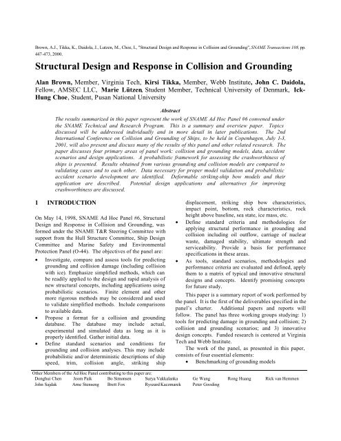
Table 1. SIMCOL EvolutionVersion 0.1 1.0 1.1 2.0 2.1SimulationExternal ModelInternal ModelHorizontalMembersVerticalMembersw/o ruptureof plateVerticalMembersw/ rupturedplateSimulation <strong>in</strong> time doma<strong>in</strong>Three degrees of freedom(Hutchison <strong>and</strong> Crake)M<strong>in</strong>orsky mechanism as re-validated by Reardon <strong>and</strong> SprungCrake’smodelJones <strong>and</strong> Van MaterCrake’smodel(Jones)Sweep<strong>in</strong>g segment method to calculate damaged area<strong>and</strong> result<strong>in</strong>g forces <strong>and</strong> momentsVanMater’sextensionof JonesNeglectedMcDermott / Rosenblatt Study methodsDoes notconsiderdeformationofwebs,frictionforce <strong>and</strong>the force topropagateyield<strong>in</strong>gzoneConsidersdeformationofwebs,frictionforce <strong>and</strong>the force topropagateyield<strong>in</strong>gzoneStrik<strong>in</strong>gbow withlimiteddepthM<strong>in</strong>orsky method forcalculat<strong>in</strong>g absorbedenergy due tolongitud<strong>in</strong>al motionIn DAMAGE 4.0, the strik<strong>in</strong>g ship bow is assumed tobe rigid. DAMAGE Version 5.0 (Released June 2000)<strong>in</strong>cludes crush<strong>in</strong>g of the bow.Based on conservation of l<strong>in</strong>ear momentum, angularmomentum <strong>and</strong> energy, the velocities after the impact arecalculated as well as the loss of k<strong>in</strong>etic energy, which isavailable for the structural deformations.In order to determ<strong>in</strong>e the deformation of the bow <strong>and</strong>the side, the strik<strong>in</strong>g ship is moved <strong>in</strong>to the struck ship <strong>in</strong>small <strong>in</strong>crements. In each <strong>in</strong>crement, the total resistanceforces from crush<strong>in</strong>g of the bow <strong>and</strong> penetration <strong>in</strong>to theside are compared. The actual crush<strong>in</strong>g/penetration<strong>in</strong>crement takes place <strong>in</strong> the ship with lowest resistance.DAMAGE 4.0 considers the material <strong>and</strong> structuralscantl<strong>in</strong>gs of all major structural components for the sidestructure.15913S1S3S5S7S9S11S13S151.80E+011.60E+011.40E+011.20E+011.00E+018.00E+006.00E+004.00E+002.00E+000.00E+00Figure 16. DAMAGE Bow GeometryThe model for the <strong>in</strong>ternal mechanics is based on thedirect contact deformation of super-elements. The superelementsused to model the side <strong>in</strong> DAMAGE are:• Shell <strong>and</strong> <strong>in</strong>ner side plat<strong>in</strong>g (laterally loadedplastic membrane)• Deck <strong>and</strong> girder crush<strong>in</strong>g• Beam loaded by a concentrated load• X-, L- <strong>and</strong> T-form <strong>in</strong>tersections crushed <strong>in</strong> theaxial directionThe bow geometry is def<strong>in</strong>ed by eight parameters.Figure 16 shows an example the bow geometry.5.2.3 ALPS/SCOLALPS/SCOL is a coarse-mesh 3-D non-l<strong>in</strong>ear f<strong>in</strong>iteelement code us<strong>in</strong>g super-elements based on the Idealized<strong>Structural</strong> Unit Method (ISUM) [20,21]. The geometry ofthe strik<strong>in</strong>g <strong>and</strong> the struck ships is described <strong>in</strong> a global(three-dimensional) rectangular coord<strong>in</strong>ate system. Thestress <strong>in</strong> an ISUM unit is described <strong>in</strong> a local elementcoord<strong>in</strong>ate system. ALPS/SCOL considers sway <strong>and</strong> yawof the struck ship with the follow<strong>in</strong>g assumptions:• The added masses of the strik<strong>in</strong>g <strong>and</strong> the struck shipsare calculated based on ships of similar type <strong>and</strong> sizeus<strong>in</strong>g a l<strong>in</strong>ear strip theory-based computer program.• The strik<strong>in</strong>g ship is assumed to be rigid.• The analysis of the external <strong>and</strong> the <strong>in</strong>ternaldynamics is undertaken separately.• The longitud<strong>in</strong>al velocity of the struck ship is notconsidered.• S<strong>in</strong>ce ALPS/SCOL is based on a simplified 3-Dnonl<strong>in</strong>ear f<strong>in</strong>ite element approach, damage <strong>in</strong> thethree directions (i.e., <strong>in</strong>clud<strong>in</strong>g penetration, vertical<strong>and</strong> horizontal damage) are considered.• The geometry of the strik<strong>in</strong>g ship bow shape isdescribed by gap/contact elements. The bow isassumed to be rigid.• One cargo hold of the struck ship is taken as theextent of the analysis.• ISUM stiffened panel units are used to model thestruck vessel structure.The geometry of the struck ship is described us<strong>in</strong>g about600 rectangular or triangular ISUM units. If thedeformation of the struck ship is symmetric, the totaldegrees of freedom <strong>in</strong> the numerical model are reduced byhalf. Each node has 3 degrees of freedom.Figure 17 shows damage calculated <strong>in</strong> anALPS/SCOL simulation.<strong>Design</strong> data required for the strik<strong>in</strong>g ship <strong>in</strong>cludes adetailed bow geometry description, length, beam, depth,draft <strong>and</strong> displacement.<strong>Design</strong> data for the struck ship <strong>in</strong>cludes, length,beam, depth, draft <strong>and</strong> displacement, transverse bulkhead10
location, COG, <strong>and</strong> detailed structural design <strong>and</strong>scantl<strong>in</strong>gs.Scenario data required <strong>in</strong>cludes strik<strong>in</strong>g ship velocity<strong>and</strong> longitud<strong>in</strong>al location of impact <strong>in</strong> the struck ship.Energy ratio10,80,60,40,260 Deg.90 Deg.120 Deg.150 Deg.Ship-Ship collision0-0,5 -0,3 -0,1 0,1 0,3 0,5<strong>Collision</strong> location (d/L)Figure 18 - Energy ratio def<strong>in</strong>ed as the ratio betweenenergy released for crush<strong>in</strong>g <strong>and</strong> the total k<strong>in</strong>etic energyof the two ships before the collision as function of thecollision location, d, for collision angles equal 60, 90, 120<strong>and</strong> 150 degrees. The two tankers are identical <strong>and</strong> havethe same speed prior to the collision [29].Figure 17. Damage from ALPS/SCOL Simulation5.2.4 DTU ModelThe Technical University of Denmark (DTU) modelalso solves the external problem uncoupled from the<strong>in</strong>ternal problem, <strong>and</strong> applies the calculated absorbedenergy to plastic deformation of the struck ship.Solution of the external dynamics is accomplishedbased on an analytical method developed by Pedersen <strong>and</strong>Zhang [29]. This method estimates the fraction of thek<strong>in</strong>etic energy that is available for deformation of the shipstructure. The energy loss for dissipation by structuraldeformation is expressed <strong>in</strong> closed-form expressions. Theprocedure is based on a rigid body mechanism, where it isassumed that there is negligible stra<strong>in</strong> energy fordeformation outside the contact region, <strong>and</strong> that thecontact region is local <strong>and</strong> small. This implies that thecollision can be considered <strong>in</strong>stantaneous as each body isassumed to exert an imp ulsive force on the other at thepo<strong>in</strong>t of contact. The model <strong>in</strong>cludes friction between theimpact<strong>in</strong>g surfaces so those situations with glanc<strong>in</strong>gblows can be identified. Both ships have three degrees offreedom: surge, sway <strong>and</strong> yaw. The <strong>in</strong>teraction betweenthe ships <strong>and</strong> the surround<strong>in</strong>g water is approximated bysimple added mass coefficients, which are assumed torema<strong>in</strong> constant dur<strong>in</strong>g the collision.The loss <strong>in</strong> k<strong>in</strong>etic energy by the method isdeterm<strong>in</strong>ed <strong>in</strong> two directions, perpendicular <strong>and</strong> parallelto the side of the struck ship. Both right <strong>and</strong> oblique anglecollisions are considered <strong>and</strong> both vessels may havevelocity before the collision.The model for the <strong>in</strong>ternal mechanics is based on aset of super-elements, where each element represents astructural component. The calculation method is based onthe pr<strong>in</strong>ciple that the area of the struck vessel affected bythe collision is restricted to the area touched by thestrik<strong>in</strong>g vessel. The super-elements are:• Lateral plate deflection <strong>and</strong> rupture. Largedeflections are assumed; this implies that the bend<strong>in</strong>gresistance can be neglected• Crush<strong>in</strong>g of structure <strong>in</strong>tersection elements (X- or T-elements)• In-plane crush<strong>in</strong>g <strong>and</strong> tear<strong>in</strong>g of plates• Beam deflection <strong>and</strong> ruptureThe design data for the struck vessel <strong>in</strong>cludes length,beam depth, draft, displacement, COG <strong>and</strong> detailedstructural design <strong>and</strong> scantl<strong>in</strong>gs.The bow of the strik<strong>in</strong>g vessel is assumed to be rigid.The basic data for describ<strong>in</strong>g the strik<strong>in</strong>g ship bow arestem angle, breadth <strong>and</strong> bow height. The horizontal shapeof the deck <strong>and</strong> the bottom are assumed to be parabolic. Ifthe strik<strong>in</strong>g vessel is equipped with a bulb, this is assumedto have the form of an elliptic parabola.Scenario data required <strong>in</strong>cludes strik<strong>in</strong>g <strong>and</strong> struckship velocity, collision angle <strong>and</strong> longitud<strong>in</strong>al location ofimpact at the struck vessel.5.3 ApplicationIn order to assess the models’ consistency <strong>and</strong> sensitivity,they are tested <strong>in</strong> a series of collision scenarios with arange of struck tanker sizes <strong>and</strong> designs. The Basel<strong>in</strong>eTanker design is a 150000 dwt double-hull tanker. It wasdeveloped to be consistent with the dimensions of the150000 dwt reference tanker <strong>in</strong> the IMO InterimGuidel<strong>in</strong>es. HECSALV <strong>and</strong> SafeHull were used to11
develop the details of the design, <strong>and</strong> to <strong>in</strong>sure that thearrangement satisfies IMO regulations <strong>and</strong> the structuraldesign satisfies ABS classification requirements. A 60000dwt double hull tanker <strong>and</strong> a 283000 dwt double tankerwere also developed <strong>in</strong> accordance with the InterimGuidel<strong>in</strong>es [3]. Results for the basel<strong>in</strong>e 150000 dwtdouble-hull tanker are presented <strong>in</strong> this paper.5.3.1 Struck ShipThe 150000 dwt Basel<strong>in</strong>e Tanker design shown <strong>in</strong> Figure19 is the primary struck ship used for the <strong>in</strong>itial modeltest<strong>in</strong>g. Tables 2 <strong>and</strong> 3 list pr<strong>in</strong>cipal characteristics <strong>and</strong>structural data for this design.Table 4 lists the <strong>in</strong>put data for each test matrix. Thefirst test matrix considers damage for a series of strikelocations on the web at the center of each cargo tank. Thisrepresents a large global variation <strong>in</strong> strike location. Thesecond test matrix considers damage for a series of strikelocations on either side of the web at the center of themidship cargo tank. This represents a relatively smalllocal variation <strong>in</strong> location on <strong>and</strong> between webs. Thethird test matrix considers damage for a series of collisionangles with a strike location on the web at the center ofthe midship cargo tank.Deadweight, tonnes 150,000Length L, m 264.00Breadth B, m 48.00Depth D, m 24.00Draft T, m 16.80Double Bottom Ht hDB, m 2.32Double Hull Width W, m 2.00Displacement, tonnes 178,8675.3.2 Model Test MatricesThree scenario test matrices were used <strong>in</strong> the <strong>in</strong>itial study.All matrices use the Basel<strong>in</strong>e Tanker as the struck ship<strong>and</strong> a 150000 dwt bulk carrier as the strik<strong>in</strong>g ship.Pr<strong>in</strong>cipal characteristics for the strik<strong>in</strong>g ship are listed <strong>in</strong>Table 4 <strong>and</strong> the result<strong>in</strong>g vertical alignment of the twoships is shown <strong>in</strong> Figure 20. S<strong>in</strong>ce the focus of the <strong>in</strong>itialtests is on penetration damage, zero struck ship speed isused <strong>in</strong> all cases. Scenarios for the test matrices aredescribed <strong>in</strong> Table 5.Table 3. Basel<strong>in</strong>e TankerShip150,000 dwtdouble hull tankerWeb Frame Spac<strong>in</strong>g L s , m 3.30Deck 47.32SmearedThicknesst h , mmInner Bottom 26.92Bottom 28.29Str<strong>in</strong>gers 3 ´ 15.34SmearedThicknesst v , mmSide Shell 21.92Inner Sk<strong>in</strong> 22.94Bulkhead 22.28Figure 19 - Basel<strong>in</strong>e Tanker <strong>Design</strong> [3]Table 2. Basel<strong>in</strong>e Tanker Pr<strong>in</strong>cipal CharacteristicsWeb Upper 12.00Thicknesst w , mm Lower 18.00Table 4. Strik<strong>in</strong>g Ship Pr<strong>in</strong>cipal Characteristics12
Ship Type150,000 dwtbulk carrierLength L, m 274.00Breadth B, m 47.00Depth D, m 21.60Bow Height H, m 26.00Draft T, m 15.96Struck Ship Speed (knt)Strik<strong>in</strong>g Ship Speed (knt)<strong>Collision</strong> Angle (deg)Strike Location (m fwd MS)5.3.3 Model ResultsDisplacement, tonnes 174,850Half Entrance Angle, α 38°Representative model results for struck ship penetrationare shown <strong>in</strong> Figures 22-27. The figures show transversepenetration <strong>in</strong>to the struck ship as a function of theparticular variables <strong>in</strong> each matrix. The results showgood agreement between the models. DAMAGEgenerally predicts the lowest penetration, <strong>and</strong>ALPS/SCOL generally predicts the highest.Figures 22 <strong>and</strong> 23 (Matrix 1) show the effect of theexternal dynamics. More energy is absorbed <strong>in</strong> strikesaround midship. SIMCOL shows a larger variation <strong>in</strong>penetration as a function of global strike location than theother models, particularly at low energy. SIMCOL’scoupled dynamics predict larger changes <strong>in</strong> the relativemotions at the strike po<strong>in</strong>t of the two ships as the strikelocation moves away from midship. This results <strong>in</strong> morelongitud<strong>in</strong>al damage <strong>and</strong> less penetration. ALPS/SCOLshows a similar, but lesser trend. This has the greatesteffect on shell <strong>and</strong> web deformation, <strong>and</strong> is most evident<strong>in</strong> the lower energy case, Figure 22.Matrix 1 0 3,4,5,6,7 90 -62.5,29.5,3.5,36.5,69.5,102.5Matrix 2 0 3,4,5,6,7 90 1.85,2.675,3.5,4.325,5.15Matrix 3 0 3,4,5,6,7 45,60,75,105,120,1353.5pen [m]Matrix 1: pen(x) Vb=3 knt43210-100 -50 0 50 100 150x [m fwd MS]DTUSIMCOL2.11DAMAGEALPS/SCOLFigure 22 – Matrix 1 Low Energy <strong>Collision</strong>Matrix 1: pen(x) Vb=7 knt150,000 dwtDouble HullTanker150,000 dwtBulk Carrierpen [m]10864DTUSIMCOL2.11DAMAGE2ALPS/SCOL0-100 -50 0 50 100 150x [m fwd MS]Figure 21 - <strong>Collision</strong> Strike Vertical AlignmentFigure 23 – Matrix 1 High Energy <strong>Collision</strong>Table 5 - Test Matrices13
• Improved model<strong>in</strong>g of longitud<strong>in</strong>al extent ofdamage <strong>in</strong>clud<strong>in</strong>g the effect of transverse webs<strong>and</strong> transverse bulkheads.• Application <strong>and</strong> comparison of models <strong>in</strong> caseswhere the struck ship has forward speed.• Application of models to other designs <strong>and</strong>assessment of damage length, beam <strong>and</strong> depthscalability with struck ship pr<strong>in</strong>cipalcharacteristics.• Struck ship design-parameter sensitivityanalysis.• Probabilistic analysis us<strong>in</strong>g scenario descriptionsdiscussed <strong>in</strong> the next section of this paper.• Model<strong>in</strong>g <strong>and</strong> application of a deformablestrik<strong>in</strong>g ship bow.6 COLLISION AND GROUNDING DATATwo basic types of data are required to support the goalsof this panel:1. Data for develop<strong>in</strong>g pdfs for ground<strong>in</strong>g <strong>and</strong> collisionscenarios.2. Data for ground<strong>in</strong>g <strong>and</strong> collision model validation,particularly for double hull damage.6.1 COLLISION AND GROUNDING SCENARIOSAs illustrated <strong>in</strong> Figure 2, probabilistic descriptions ofground<strong>in</strong>g <strong>and</strong> collision scenarios are required to developprobabilistic descriptions of ground<strong>in</strong>g <strong>and</strong> collisiondamage.The follow<strong>in</strong>g data are required to def<strong>in</strong>e ground<strong>in</strong>gscenarios:• Bottom or obstacle description• Depth of water• Ground<strong>in</strong>g ship displacement, trim, draft<strong>and</strong> speed• Location of the obstacle relative to the ship'scenterl<strong>in</strong>eA longer list is required for collision:• Strik<strong>in</strong>g ship• Speed• Displacement• Draft• Bow height• Bow shape• <strong>Collision</strong> angle• Strike location• Struck ship• Speed• DisplacementThe pdfs for these variables are not <strong>in</strong>dependent. Possiblerelationships for the collision variables are illustrated <strong>in</strong>Figure 28. Given the struck ship design <strong>and</strong> requirement:1. S<strong>in</strong>ce specific struck ships trade <strong>in</strong> specific ports onspecific routes, it is expected that they will encountera related subset or distribution of other ships (strik<strong>in</strong>gships) that may not be a distribution represent<strong>in</strong>g allships <strong>in</strong> worldwide trade.2. A specific struck ship with known designcharacteristics <strong>in</strong> a specific trade will also haverelated distributions for draft, trim <strong>and</strong> speed. Note:this speed is the speed at the moment of the collision,<strong>and</strong> not necessarily operat<strong>in</strong>g speed.3. Given a specific type <strong>and</strong> tonnage of strik<strong>in</strong>g ship, itsother characteristics will also be related <strong>in</strong>clud<strong>in</strong>gdisplacement/mass, bow half entrance angle, bowheight, draft, bow stiffness or structural design <strong>and</strong>speed. Aga<strong>in</strong>, this is speed at the moment ofcollision, not operat<strong>in</strong>g speed.4. When two ships are maneuver<strong>in</strong>g to avoid a collision(<strong>in</strong>-extremis), the result<strong>in</strong>g collision angle <strong>and</strong> strikelocation are expected to be related.<strong>Collision</strong> AngleStruck Ship<strong>Design</strong>241Struck ShipSpeedStruck ShipTrimStruck ShipDraftStrike LocationStrik<strong>in</strong>g ShipTypeStrik<strong>in</strong>g ShipDwt3Strik<strong>in</strong>g ShipBow HEAStrik<strong>in</strong>g ShipBow HeightStrik<strong>in</strong>g ShipBow StiffnessStrik<strong>in</strong>g ShipLBP, B, DStrik<strong>in</strong>g ShipDisplacement,Mass,Draft,TrimStrik<strong>in</strong>g ShipSpeedFigure 28. <strong>Collision</strong> Scenario Variable RelationshipsThe data necessary to establish these relationships is verylimited. Collection <strong>and</strong> analysis of this data is ongo<strong>in</strong>g.15
6.2 DATA FOR MODEL VALIDATIONThe second type of data required by the panel is for modelvalidation. In collision the follow<strong>in</strong>g data is required:• <strong>Collision</strong> Scenario• Strik<strong>in</strong>g ship• Speed• Displacement• Draft• Bow height• Type• <strong>Collision</strong> angle• Strike location• Struck ship design• L,B,D,T,∆• Speed• <strong>Structural</strong> design• h DB , w DS , y LBHD , x TBHD• web spac<strong>in</strong>g, z str<strong>in</strong>g , z strut• scantl<strong>in</strong>gs• Damage descriptionIn ground<strong>in</strong>g, the follow<strong>in</strong>g model validation data isrequired:• Ground<strong>in</strong>g Scenario• Geometry <strong>and</strong> elevation of the rock• Location of the rock relative to the ship'scenterl<strong>in</strong>e• Ship speed, draft, displacement <strong>and</strong> trim• Grounded ship design• Hull type (s<strong>in</strong>gle hull, double hull, mid -deck, …)• L, B, D, LCG, LCF, GM T , GM L• Waterplane area• Transverse <strong>and</strong> longitud<strong>in</strong>al bulkhead locations• Frame spac<strong>in</strong>g, spac<strong>in</strong>g of longitud<strong>in</strong>al girders• Scantl<strong>in</strong>gs• Damage description7 STRIKING SHIP BOW7.1 SIMCOL Bow Model StudyAll of the collision models used thus far <strong>in</strong> this study, <strong>and</strong>most models used by other researchers, assume that thestrik<strong>in</strong>g ship bow is rigid. This is chang<strong>in</strong>g. Panel work<strong>in</strong> this area is focused on the follow<strong>in</strong>g questions <strong>and</strong>problems:1. Is the rigid bow assumption rational? Is significantenergy absorbed by the strik<strong>in</strong>g ship bow? Is thisenergy variable <strong>in</strong> different collision scenarios?2. If bow deformation is important, can this problem besolved uncoupled from the side damage problem?3. Identify a simple, but sufficient bow model for futureuse <strong>in</strong> SIMCOL.4. Develop a course-mesh bow model to speed upLSDYNA model<strong>in</strong>g for SIMCOL validation.Most collision accidents that result <strong>in</strong> significantstruck ship damage also result <strong>in</strong> significant damage tothe strik<strong>in</strong>g ship bow. M<strong>in</strong>orsky’s orig<strong>in</strong>al analysis [26]considered absorbed energy <strong>in</strong> the strik<strong>in</strong>g bow. Areanalysis of his data <strong>in</strong>dicates that absorbed bow energy<strong>in</strong> these cases accounted for between 8 <strong>and</strong> 53 percent ofthe total absorbed energy [30]. More recent studies byReckl<strong>in</strong>g [31], Akita <strong>and</strong> Kitamura [32], <strong>and</strong> Valsgard <strong>and</strong>Pettersen [33] <strong>in</strong>dicate absorbed bow energies <strong>in</strong> the rangeof 42 to 55 percent of the total absorbed energy.LSDYNA analyses conducted at Virg<strong>in</strong>ia Tech withdeformable bows <strong>and</strong> sides show absorbed bow energies<strong>in</strong> the range of 22 to 44 percent [30]. We mu st concludethat absorbed bow energy can be significant <strong>and</strong> variable,<strong>and</strong> therefore should be considered <strong>in</strong> collision analyses.The availability of this data is extremely limited.Accident data from USCG databases for the period of1980-1998 was screened for sufficiency <strong>and</strong> applicabilityto this problem. Useful validation cases must <strong>in</strong>clude allof the data specified above (scenario, structural design,damage description). In the case of collision, thefollow<strong>in</strong>g additional criteria were applied:• Strik<strong>in</strong>g location <strong>in</strong> struck ship away from bow orstern.• <strong>Collision</strong> angles of 45-135 degrees.• Penetration greater than one meter.Collection <strong>and</strong> evaluation of this data is also ongo<strong>in</strong>g.Table 6. Bow Model Test Matrix16
Table 6 lists the bow <strong>and</strong> struck ship model casesconsidered <strong>in</strong> the SIMCOL bow model development.Four rigid bow tests were run to validate SIMCOLcalculations. These are labeled R-1 through R-4 <strong>in</strong> Table6. Ten conventional FEA bow analyses were run tovalidate the simpler <strong>in</strong>tersection bow model results. Theseare labeled C-1 through C-10 <strong>in</strong> Table 6. Two types of<strong>in</strong>tersection model analyses were accomplished. Tests I-1through I-4 use closed-form equations from Pedersen[34], Amdahl [35], <strong>and</strong> Yang <strong>and</strong> Caldwell [36]. Tests I-5 through I-16 use <strong>in</strong>tersection elements applied <strong>in</strong>LSDYNA simulations.Simplified LSDYNA <strong>in</strong>tersection-element bowmodels were developed to <strong>in</strong>crease the speed ofLSDYNA f<strong>in</strong>ite element solutions used <strong>in</strong> SIMCOLcollision model validation. In these models, only<strong>in</strong>tersections of sides, decks, longitud<strong>in</strong>al bulkheads <strong>and</strong>girders were <strong>in</strong>cluded <strong>in</strong> the model with longitud<strong>in</strong>alstiffener area smeared <strong>in</strong>to plate thickness based onplastic bend<strong>in</strong>g moment. Intersection elements aremodeled as truss elements <strong>in</strong> LSDYNA with materialproperties replaced by properties derived for crushed L, T<strong>and</strong> cruciform sections as illustrated <strong>in</strong> Figure 29 [35].Transverse frames were modeled as normal trusselements. Nodes were only allowed a s<strong>in</strong>gle degree offreedom <strong>in</strong> the strik<strong>in</strong>g ship longitud<strong>in</strong>al direction. The150kdwt bulk carrier bow is shown <strong>in</strong> Figure 30 [34].Figure 31 shows the <strong>in</strong>tersection model for this bow (I-8).Figure 32 shows the conventional f<strong>in</strong>e-mesh FEM for thisbow with beam <strong>and</strong> panel elements (C-5). Figure 33shows a comparison of the force-<strong>in</strong>dentation plots for the<strong>in</strong>tersection <strong>and</strong> conventional models (I-8 <strong>and</strong> C-2). Theresults compare very well. Similar results were obta<strong>in</strong>edfor the other test cases. It is concluded that the bow<strong>in</strong>tersection model is sufficient for LSDYNA collisionsimulations. Work is cont<strong>in</strong>u<strong>in</strong>g to apply these results tothe development of a SIMCOL bow model.Forecastle Deck, 26.0m abl.Tank Top, 20.0 m abl.<strong>Collision</strong> Bhd.Tl =15.96mDeck (not W.T.), 7.6mabl.LoadedFigure 30 - 150kdwt Bulk Carrier Bow [34]Figure 31 - Bulk Carrier Intersection Element Model [30]Figure 29 - Intersection element Model [35]Figure 32 - Bulk Carrier Conventional FE Bow17
Force (N)8.00E+087.00E+086.00E+085.00E+084.00E+083.00E+082.00E+081.00E+08Intersection ModelConventional Model0.00E+000 5 10 15 20 25 30Penetration (m)Figure 33 - 150kdwt Bulk Carrier Strik<strong>in</strong>g Rigid Wall[30]7.2 DAMAGE Bow ModelDAMAGE 5.0 <strong>in</strong>cludes a deformable bow. The <strong>in</strong>itialbow geometry is the same as <strong>in</strong> Damage 4.0, illustrated <strong>in</strong>Figure 16. Bow crush<strong>in</strong>g is modeled us<strong>in</strong>g L-, T- <strong>and</strong> X-form super-elements <strong>in</strong> an ‘<strong>in</strong>tersect<strong>in</strong>g unit method’ [37].Bow <strong>and</strong> side force-deformation calculations arecompleted separately (uncoupled). These calculations areperformed assum<strong>in</strong>g that the bow strikes a rigid wall <strong>and</strong>that the side is struck by a rigid bow. The results are thencompared <strong>in</strong>crementally with deformation applied to theweakest component (bow or side) at each <strong>in</strong>crement.This results <strong>in</strong> deformation <strong>and</strong> energy absorption <strong>in</strong> bothcomponents.7.3 DTU Bow Model [38]Strik<strong>in</strong>g VesselDeformation of the Strik<strong>in</strong>g VesselA’’ A’comparison of the crush<strong>in</strong>g forces for respectively thebow <strong>and</strong> the side, it can be determ<strong>in</strong>ed which vesseldeforms dur<strong>in</strong>g the considered step.Before calculation of the deformation of the twovessels the follow<strong>in</strong>g calculations are carried out:1. The Force-Penetration curve F struck (δ A ) for the struckvessel is calculated, where the strik<strong>in</strong>g vessel is rigid.2. The Force-Penetration curve F strik<strong>in</strong>g (δ B ) for thestrik<strong>in</strong>g vessel is calculated, where the struck vesselis assumed rigid.If the strik<strong>in</strong>g vessel has a bulbous bow, the analysis ofthe crush<strong>in</strong>g forces is separated <strong>in</strong>to a bulb analysis <strong>and</strong>an analysis of the top of bow above the bulb.The force-deformation curve for the struck vessel isdeterm<strong>in</strong>ed by the procedure described <strong>in</strong> Section 5.2.4<strong>and</strong> for the strik<strong>in</strong>g vessel by the procedure described <strong>in</strong>Pedersen et. al [34].A commonly used procedure for tak<strong>in</strong>g <strong>in</strong>to accountthe deformation of the bow is to compare the two forcepenetrationcurves, F struck (δ A ) <strong>and</strong> F strik<strong>in</strong>g (δ B ), at each step.This approach, however, only <strong>in</strong>cludes a very limitedlevel of <strong>in</strong>teraction. In reality, the force-penetration curvefor the side of the struck vessel is a function of thedeformation of the bow, <strong>and</strong> vice versa. This stronger<strong>in</strong>teraction is taken <strong>in</strong>to account by compar<strong>in</strong>g the forcesF A <strong>and</strong> F B , which is determ<strong>in</strong>ed as:A'Struck vessel: FA= FStruck( δ A )(1)A''F = δ + δ(2)Strik<strong>in</strong>g vessel: ( )B F Strik<strong>in</strong>gwhereF A force to crush the struck vessel;F B force to crush the strik<strong>in</strong>g vessel;F struck force from the force-penetration curve for struckvessel, where the strik<strong>in</strong>g vessel is rigid;F strik<strong>in</strong>g force from the force-penetration curve forstrik<strong>in</strong>g vessel, where the struck vessel is rigid;δ A penetration <strong>in</strong>to the struck vessel;δ B deformation of the strik<strong>in</strong>g vessel;A’ cross-sectional area of the strik<strong>in</strong>g vessel takenat a distance of δ A +δ B from bow or bulb tip;A’’ cross-sectional area of the strik<strong>in</strong>g vessel takenat a distance of δ A from bow or bulb tip;See also Figure 34.ABδ Aδ BStruck VesselFigure 34 - Deformation of vessels dur<strong>in</strong>g collision. TheA’s relate to areas not lengthsA more recent DTU model also predicts damage tostruck <strong>and</strong> strik<strong>in</strong>g vessels <strong>in</strong> a collision event [38]. Theanalysis is carried out <strong>in</strong> penetration steps. Only one ofthe <strong>in</strong>volved vessels can be deformed <strong>in</strong> each step. By aThe forces at the struck <strong>and</strong> the strik<strong>in</strong>g vessel F A <strong>and</strong> F Bare compared• If F A > F BDeformation of strik<strong>in</strong>g vessel, δ B is <strong>in</strong>creased• If F B > F ADeformation of struck vessel, δ A is <strong>in</strong>creasedThe reason for correct<strong>in</strong>g the resistance of the struckvessel is that if the bow is deformed, the resistance isapproximately equal to the force at the side times the ratiobetween the areas. For a s<strong>in</strong>gle hull vessel the correction18
will have nearly no <strong>in</strong>fluence, but for a double hull vessel,there will be some corrections when the bow penetratesthe <strong>in</strong>ner side. See Figure 34.When the deformation patterns of the struck <strong>and</strong> thestrik<strong>in</strong>g vessel are known, the total absorbed energy canbe calculated <strong>and</strong> compared with the energy calculated bythe external dynamics. See Pedersen <strong>and</strong> Zhang [29].present, <strong>and</strong> the overwhelm<strong>in</strong>g majority of s<strong>in</strong>gle-sk<strong>in</strong>neddesigns are longitud<strong>in</strong>ally stiffened. OPA ’90 m<strong>and</strong>atesthe use of double-sk<strong>in</strong>ned tanker designs, Figure 36 [39].8 STRUCTURAL DESIGN FOR COLLISIONAND GROUNDINGThe function of a tank vessel’s structural system may beviewed from the st<strong>and</strong>po<strong>in</strong>ts of normal operation <strong>and</strong>casualty operation. In provid<strong>in</strong>g adequate resistance fornormal operations, the objective <strong>in</strong> structural design is toma<strong>in</strong>ta<strong>in</strong> structural <strong>in</strong>tegrity of the hull girder, ofbulkheads, decks, etc., <strong>and</strong> of plat<strong>in</strong>g, stiffeners <strong>and</strong>details. Other considerations relate to vessel size,complexity <strong>and</strong> heav<strong>in</strong>ess of structure, producibility <strong>and</strong>ma<strong>in</strong>ta<strong>in</strong>ability. In terms of casualty operations, theobjective is to ma<strong>in</strong>ta<strong>in</strong> vessel <strong>in</strong>tegrity <strong>and</strong> to protectcargo, or conversely to protect the environment from oilpollution <strong>in</strong> case of a casualty. In this case the primaryconsiderations should <strong>in</strong>clude:1. Resistance to fire <strong>and</strong> explosion damage <strong>and</strong> itsconta<strong>in</strong>ment,2. Resistance to collision <strong>and</strong> ground<strong>in</strong>g damage,3. Conta<strong>in</strong>ment of petroleum outflow if damage doesoccur, <strong>and</strong>4. Ma<strong>in</strong>tenance of sufficient residual strength afterdamage <strong>in</strong> order to permit salvage <strong>and</strong> rescueoperation <strong>and</strong> to m<strong>in</strong>imize further damage <strong>and</strong>spill<strong>in</strong>g of oil.Figure 36 - Double-Hull Tanker [39]The Mar<strong>in</strong>e Board of the National Research Councilhas recently convened a "Committee on Evaluat<strong>in</strong>gAlternative Tanker <strong>Design</strong>s". The committee is toestablish, for the first time, a rational methodology toevaluate alternatives to the double hull. The US CoastGuard is sponsor<strong>in</strong>g this Committee, <strong>and</strong> its report isexpected <strong>in</strong> the first quarter of 2001.The emphasis of new <strong>and</strong> proposed requirements forreduc<strong>in</strong>g the probability of oil cargo outflow has been onthe subdivision of cargo spaces. The impact of hullstructure on the reduction of outflow has had more limitedattention. The complexity of determ<strong>in</strong><strong>in</strong>g the contributionof structure to cargo protection <strong>and</strong> the unpredictability ofstructural response under the variety of potential damagescenarios have no doubt contributed to this set ofcircumstances.The follow<strong>in</strong>g subsections address the subject ofvessel structural design characteristics for collision,ground<strong>in</strong>g <strong>and</strong> bow impact. The <strong>in</strong>tent is to consider whathas been learned from analytical studies regard<strong>in</strong>gstructural design features that may suggest futuremodifications <strong>and</strong> alternatives to enhance resistance tocargo outflow.8.1 <strong>Collision</strong>s8.1.1 Analytical Indications – Struck ShipFigure 35 - S<strong>in</strong>gle-Hull Tanker [39]Tank vessels have traditionally been designed ass<strong>in</strong>gle-sk<strong>in</strong>ned hulls, Figure 35 [39]. Depend<strong>in</strong>g on thesize of the vessel, longitud<strong>in</strong>al bulkheads are oftenThe sequence of structural events dur<strong>in</strong>g a collision variesaccord<strong>in</strong>g to the nature of the collision <strong>and</strong> vessel design.Figures 37 <strong>and</strong> 38 [24] provide general flow diagramsrepresent<strong>in</strong>g the phenomena for s<strong>in</strong>gle <strong>and</strong> double hulltankers. This <strong>in</strong>formation is useful <strong>in</strong> identify<strong>in</strong>g wheregreater resistance can be addressed.19
Figure 37 - Macro flow diagram for side collision plastic-energy analysis of a s<strong>in</strong>gle hull [24]Initially, the stiffened hull plat<strong>in</strong>g distorts <strong>in</strong> a plasticbend<strong>in</strong>g phase, with plastic “h<strong>in</strong>ges’ form<strong>in</strong>g <strong>in</strong> thevic<strong>in</strong>ities of the strike <strong>and</strong> the web frames flank<strong>in</strong>g thestrike. Dur<strong>in</strong>g this phase, <strong>in</strong>significant membrane tensiondevelops. For a typical tanker with longitud<strong>in</strong>al anglesstiffen<strong>in</strong>g the hull plat<strong>in</strong>g, the longitud<strong>in</strong>al angle -shapedstiffeners then buckle <strong>in</strong> the vic<strong>in</strong>ity of the flank<strong>in</strong>g webframes, <strong>and</strong> possibly “trip” <strong>in</strong> the vic<strong>in</strong>ity of the strike.Subsequently, the stiffened hull unloads momentarily asthe strike cont<strong>in</strong>ues, but reloads <strong>in</strong> a membrane-tensionphase. The hull ruptures at the end of this phase, withpossibly the flank<strong>in</strong>g web frames yield<strong>in</strong>g or buckl<strong>in</strong>g
efore the hull ruptures. In such cases, the me mbranetensionphase <strong>in</strong>cludes two sub-phases: (1) there is notransverse movement of the web frames flank<strong>in</strong>g thestrike; <strong>and</strong> (2) the web frames flank<strong>in</strong>g the strike move<strong>in</strong>ward toward the ship’s centerl<strong>in</strong>e, <strong>and</strong> the damageextends <strong>in</strong>to the adjacent web frame spaces. Dur<strong>in</strong>g thesephases, the deck is also distort<strong>in</strong>g <strong>in</strong> membrane tension.However, the deck behavior is assumed not to affect thesequences of the options.Other sequences of phenomena are possible. A hullwith longitud<strong>in</strong>al stiffeners, such as rectangular bars thatare not apt to buckle or trip, tend to rupture beforesignificant membrane tension has a chance to develop.Alternatively, with any type of hull stiffeners, veryweak web frames can yield or buckle before rupture orbuckl<strong>in</strong>g of the longitud<strong>in</strong>al stiffeners, <strong>in</strong> which case thedamaged length <strong>in</strong>creases dur<strong>in</strong>g the bend<strong>in</strong>g phase.These phenomena are unlikely, however, for typicalships.Figure 38 - Macro flow diagram for side collision plastic-energy analysis of a double hull [24]21
enhance resistance to collision. These fall <strong>in</strong>to twocategories:Figure 39 - Energy Absorption of <strong>Structural</strong> Components(St<strong>and</strong>ard VLCC) [40]Figure 40 - Energy Absorption Capacity [40]The contribution of various structural components fora ULCC with a more conventional double side structure isshown <strong>in</strong> Figure 39 [40].8.1.2 ApplicationWith the knowledge acquired from underst<strong>and</strong><strong>in</strong>g theprocess identified by the analytical evaluations, it ispossible to postulate hull structural features that may• Conventional hull structural arrangements that aremodified to enhance energy absorption.• Unconventional hull structural arrangements that<strong>in</strong>clude structurally actuated mechanisms for energyabsorption.As part of the research project for improved tankersafety aga<strong>in</strong>st collision <strong>and</strong> ground<strong>in</strong>g, the Association for<strong>Structural</strong> Improvement of the Shipbuild<strong>in</strong>g Industry(ASIS) of Japan conducted a study of vary<strong>in</strong>g structuralcharacteristics of a conventional VLCC design <strong>and</strong>apply<strong>in</strong>g a more unconventional structural feature as well[40]. The more conventional alterations <strong>in</strong>cluded use ofhigh strength steel, additional shell str<strong>in</strong>gers, alongitud<strong>in</strong>al strut <strong>in</strong> the outboard cargo tank support<strong>in</strong>gthe double side, <strong>and</strong> a double side unidirectionalstiffen<strong>in</strong>g system. As the side-shell has shown to be asignificant contributor to energy absorption, anunconventional new sk<strong>in</strong> composed of double plate panels<strong>in</strong>ternally stiffened by web frames, essentially a coredpanel sk<strong>in</strong> provid<strong>in</strong>g additional net shell thickness, wassubstituted for the conventional stiffened plate. Theresults are shown <strong>in</strong> Figure 40. Other ideas of the moreconventional nature <strong>in</strong>cluded:• Bulkhead stools on the w<strong>in</strong>g tank side to reduce hardspots <strong>and</strong> <strong>in</strong>crease damage length.• Reduced stiffness of web frames to <strong>in</strong>crease damagelength.• Increased side-shell plat<strong>in</strong>g thickness, especiallyfrom the ballast waterl<strong>in</strong>e up, to <strong>in</strong>crease membranetension <strong>in</strong> the side-shell.• Decreased spac<strong>in</strong>g of side-shell longitud<strong>in</strong>als <strong>and</strong>added <strong>in</strong>termediate vertical web frames on the sideshell to <strong>in</strong>crease the <strong>in</strong>tegrity of the side-shell.• Increased number of horizontal str<strong>in</strong>gers <strong>in</strong> the w<strong>in</strong>gtank to <strong>in</strong>crease side sk<strong>in</strong> <strong>in</strong>tegrity <strong>and</strong> provideadditional material for membrane tension.Although the practicability <strong>and</strong> acceptance from aregulatory po<strong>in</strong>t of view of very unconventionalapproaches may be seriously <strong>in</strong> doubt, it is neverthelesspossible to postulate alternatives, <strong>and</strong> <strong>in</strong> fact the greateststep <strong>in</strong> the level of possible energy absorption is likelywith an unconventional approaches:• Controlled pressure fluid chamber <strong>in</strong> the w<strong>in</strong>g tankswhere<strong>in</strong> the vent<strong>in</strong>g of fluid under pressure to otherspaces when compressed dur<strong>in</strong>g collision results <strong>in</strong>energy dissipation.• Introduction of material <strong>in</strong> w<strong>in</strong>g ballast-tanks thatdoes not reduce ballast capacity significantly, but<strong>in</strong>creases energy absorption, like ultra-large open-cell
foam. Permeability <strong>and</strong> <strong>in</strong>spection are possibleproblems with this approach.• Truss structure separat<strong>in</strong>g w<strong>in</strong>g tank sk<strong>in</strong>s. Such anarrangement can enhance the <strong>in</strong>tegrity of the <strong>in</strong>nerhull longer as the truss deforms while support<strong>in</strong>g theouter sk<strong>in</strong> <strong>and</strong> more slowly load<strong>in</strong>g the <strong>in</strong>ner sk<strong>in</strong>.• Pre-planned failure or “crumple zones” as have beendeveloped by the automobile <strong>in</strong>dustry for the morecritical <strong>and</strong> predictable areas of damage.• A foam release system actuated <strong>in</strong> the event of animpend<strong>in</strong>g collision with<strong>in</strong> the expected area ofcontact to <strong>in</strong>crease stiffness <strong>and</strong> energy absorption.8.2 Bow Impact8.2.1 Analytical IndicationsThe significance of the energy absorption <strong>in</strong> bow damage<strong>and</strong> the effects of the bow <strong>in</strong>teract<strong>in</strong>g with the struckship’s side structure make it a critical element <strong>in</strong>consider<strong>in</strong>g collision results. Calculations assum<strong>in</strong>g rigidbows with vertical stems <strong>and</strong> no bulbs have simplifiedanalyses <strong>and</strong> fostered underst<strong>and</strong><strong>in</strong>g, but do not depict thecurrent <strong>and</strong> likely future nature of bows. Ship resistance,power<strong>in</strong>g <strong>and</strong> seakeep<strong>in</strong>g requirements are likely tocont<strong>in</strong>ue to foster the existence of bows with raked stems<strong>and</strong> bulbs <strong>in</strong>to the future.Analytical evaluations do po<strong>in</strong>t a way to consider<strong>in</strong>gbows. If they are deformable, they will account for asizeable portion of the total energy absorption <strong>in</strong> acollision. If they can be made to deform <strong>in</strong> a manner thatdoes not cause premature failure of important struck shipenergy absorb<strong>in</strong>g structure, such as the side shell, then thesame attributes of a rigid vertical stem bow will beachieved at the struck vessel.8.3 ApplicationThe bows of ships <strong>in</strong>corporate a significant amount ofstiff horizontal fore <strong>and</strong> aft re<strong>in</strong>forc<strong>in</strong>g structural elementsthat enhance the rigidity of the structure. Alternatively,arrangements with transverse stiffen<strong>in</strong>g coupled withappropriate spac<strong>in</strong>g can lead to significant fold<strong>in</strong>gdeformation, which can effectively reduce or elim<strong>in</strong>atethe protrusions of the upper bow <strong>and</strong> bulb as well as theirstructural hard-spots. Recent studies [44] have confirmedthat lower crush<strong>in</strong>g pressure of a bulbous bow ispreferable to avoid the early rupture of the strucksideshell <strong>and</strong> the crush<strong>in</strong>g strength should not exceed thatof the side structure.8.4 Ground<strong>in</strong>g8.4.1 Analytical Indications – Ground<strong>in</strong>gThe potential phases of ground<strong>in</strong>g are depicted <strong>in</strong> Figure41. In ground<strong>in</strong>g <strong>and</strong> rak<strong>in</strong>g, the vessel has forwardspeed. In str<strong>and</strong><strong>in</strong>g it does not.Model test<strong>in</strong>g <strong>and</strong> computer f<strong>in</strong>ite element simulationof a str<strong>and</strong><strong>in</strong>g for a 280000 dwt tanker double bottomresulted <strong>in</strong> the lateral load versus <strong>in</strong>dentation of up to 2mshown <strong>in</strong> Figure 42. The peak po<strong>in</strong>t, po<strong>in</strong>t 1, denotes thebuckl<strong>in</strong>g of the center longitud<strong>in</strong>al girder, <strong>and</strong> po<strong>in</strong>t 2, thefracture of the outer bottom plat<strong>in</strong>g. Po<strong>in</strong>t 3 <strong>in</strong>dicatesfracture of the center girder-floor connection. It is<strong>in</strong>terest<strong>in</strong>g to note that the response shown <strong>in</strong> Figure 42 issimilar to that predicted for collision, with the pr<strong>in</strong>cipaldifference be<strong>in</strong>g the nature of the obtrusive load<strong>in</strong>g,which may be a l<strong>in</strong>e load for a collision <strong>and</strong> a po<strong>in</strong>t loadfor a ground<strong>in</strong>g.Rak<strong>in</strong>g bottom damage is of significantly differentcharacter than the ground<strong>in</strong>g damage heretoforediscussed. In rak<strong>in</strong>g damage, the obstruction ruptures thebottom structure <strong>and</strong> then cont<strong>in</strong>ues destructive shear<strong>in</strong>g,tear<strong>in</strong>g <strong>and</strong> buckl<strong>in</strong>g as the vessel cont<strong>in</strong>ues to move <strong>in</strong> itsdirection of motion, Figure 43. The length of bottomrak<strong>in</strong>g is based on an energy balance concept where thek<strong>in</strong>etic energy of the vessel is entirely absorbed by thedestruction of bottom structure.Figure 41 - Model of the ground<strong>in</strong>g process [41,42]An energy analysis for ground<strong>in</strong>g which takes <strong>in</strong>toaccount energy due to the tear<strong>in</strong>g that occurs dur<strong>in</strong>gtrack<strong>in</strong>g-type collisions presumes that <strong>in</strong> such cases thedamage will be long <strong>and</strong> shallow, <strong>in</strong>volv<strong>in</strong>g plate tear<strong>in</strong>g,but relatively little volume distortion of the <strong>in</strong>nerstructure. However, Figure 42 <strong>in</strong>dicates that if there is avertical component to the strik<strong>in</strong>g force, after fracture ofthe outer plat<strong>in</strong>g at po<strong>in</strong>t 2, there is an <strong>in</strong>crease <strong>in</strong> stiffnesslead<strong>in</strong>g up to po<strong>in</strong>t 3 <strong>and</strong> beyond as more girders <strong>and</strong>floors come <strong>in</strong>to contact with the obstruction. Figure 44also <strong>in</strong>dicates a retention of stiffness.23
Figure 42 - Load versus lateral <strong>in</strong>dentation for 280000dwt tanker double bottom [42]Figure 43 - Bottom rak<strong>in</strong>g due to ground<strong>in</strong>g8.4.2 ApplicationIn resist<strong>in</strong>g both ground<strong>in</strong>g <strong>and</strong> rak<strong>in</strong>g damage, it is clearthat the bottom shell <strong>and</strong> the <strong>in</strong>ternal grid of thetransverse floors, longitud<strong>in</strong>al girders <strong>and</strong> bulkheads iscritical.In the case of rak<strong>in</strong>g damage, the longitud<strong>in</strong>alstiffness of floors <strong>and</strong> their ability to absorb energy <strong>in</strong>distortion are more critical than their support of the shell.As <strong>in</strong> this case the distort<strong>in</strong>g force is applied <strong>in</strong> theweakest direction of the floor, the situation is furthercomplicated. Clearly, the more floors <strong>and</strong> the smaller thespans between their longitud<strong>in</strong>ally resistive structure, thebetter. On the other h<strong>and</strong>, this arrangement will serve tolimit the lateral deflection <strong>and</strong> therefore, the energyabsorption <strong>in</strong> a str<strong>and</strong><strong>in</strong>g. Other ideas have <strong>in</strong>cluded:• Increase the scantl<strong>in</strong>gs of the lower one-third part ofthe hull.• Slope the <strong>in</strong>ner bottom, higher at the collisionbulkhead <strong>and</strong> lower<strong>in</strong>g to the regulatory requirementat the end of the first cargo tank.• Preclude web frame <strong>and</strong> bulkhead damagepropagation through the <strong>in</strong>ner bottom by <strong>in</strong>troduc<strong>in</strong>ga discont<strong>in</strong>uity <strong>in</strong> the rigidity between the two. Abulkhead stool would be an example.9 CONCLUSIONSFigure 44 - Rak<strong>in</strong>g force versus penetration length byexperiments [41]The almost two-year effort of the panel has achieved orpartially achieved many of the orig<strong>in</strong>al objectives stated<strong>in</strong> the <strong>in</strong>troduction to this paper:• Simplified ground<strong>in</strong>g models have been <strong>in</strong>vestigated,compared <strong>and</strong> assessed. DAMAGE 4.0 is shown tobe an excellent tool for comparative analysis ofground<strong>in</strong>g damage, <strong>and</strong> based on limited validation,provides good results for cases with similar idealizedrock geometry. More validation is required.Limitations <strong>in</strong>clude the ability to consider onlyconventional ship geometries <strong>and</strong> an idealizedp<strong>in</strong>nacle geometry. Ground<strong>in</strong>g on other rockgeometries, reefs, etc., cannot be analyzed us<strong>in</strong>gDAMAGE, but should be considered <strong>in</strong> the future asan important part of a complete probabilistic analysis.Only a prelim<strong>in</strong>ary attempt at probabilistic analysisus<strong>in</strong>g DAMAGE was completed.• Four simplified collision models have been<strong>in</strong>vestigated, compared <strong>and</strong> assessed. The modelsprovide similar penetration results for the casesconsidered. Although some limited validation hasbeen accomplished for specific mechanisms used <strong>in</strong>the models, more validation is required. Theprediction of longitud<strong>in</strong>al extent of damage,particularly at transverse bulkheads, rema<strong>in</strong>s largelyunexplored. This is very important for oil outflow<strong>and</strong> damage stability calculations. This prediction24
equires consideration of various collision angles <strong>and</strong>struck ship speed. Consideration of strik<strong>in</strong>g bowdeformation is a relatively new addition to thecollision models. Further application <strong>and</strong> validationof bow models <strong>and</strong> their coupl<strong>in</strong>g to struck shipmodels is required. Most of the researchers are us<strong>in</strong>gf<strong>in</strong>ite element analysis as part of simplified modelvalidation. Only a prelim<strong>in</strong>ary attempt atprobabilistic analysis us<strong>in</strong>g SIMCOL was completed.Additional analysis is <strong>in</strong> progress.• Data for model validation <strong>and</strong> scenario def<strong>in</strong>ition isvery limited. A proposed data requirement isspecified <strong>in</strong> this paper. The search for data to fill therequirement goes on with the support of the USCG,SSC <strong>and</strong> SNAME. Fund<strong>in</strong>g <strong>and</strong> significant IMO<strong>and</strong> class society support may ultimately benecessary to fully satisfy this data requirement.• Some progress has been made <strong>in</strong> the def<strong>in</strong>ition ofscenarios <strong>and</strong> conditions for ground<strong>in</strong>g <strong>and</strong> collisionanalyses, but limited data is also hamper<strong>in</strong>g thiseffort. Data describ<strong>in</strong>g the worldwide population ofships that might be <strong>in</strong>volved <strong>in</strong> collisions is available,but s<strong>in</strong>ce specific struck ships trade <strong>in</strong> specific portson specific routes, it is expected that they willencounter a related subset or distribution of otherships (strik<strong>in</strong>g ships). Sufficient data has not beenobta<strong>in</strong>ed to quantify or assess this hypothesis. Moredata is also required for collision angle, strikelocation, ground<strong>in</strong>g <strong>and</strong> collision ship speeds <strong>and</strong>ground<strong>in</strong>g bottom description.• A number of possibilities for design improvement arepresented <strong>in</strong> the paper. As tools, st<strong>and</strong>ard scenarios,methodologies <strong>and</strong> performance criteria are evaluated<strong>and</strong> def<strong>in</strong>ed they must be used to assess <strong>in</strong>novativedesigns, <strong>and</strong> to optimize <strong>and</strong> evaluate conventionaldesigns. Damage models should be applied <strong>in</strong> a totalship design framework to trade-off variations <strong>in</strong>structural design, subdivision <strong>and</strong> systemredundancy.• The application of this work <strong>in</strong> a regulatoryframework requires that a very simplified, preferablyparametric relationship be established betweenstructural design variables <strong>and</strong> probabilistic damage.This work rema<strong>in</strong>s to be done.10 SIGNIFICANCEThis work is not done. Ground<strong>in</strong>g <strong>and</strong> collision modelshave been improved, data requirements have beendef<strong>in</strong>ed, <strong>and</strong> design possibilities for improvedcrashworth<strong>in</strong>ess have been identified, but this work mustbe f<strong>in</strong>ished <strong>and</strong> validated before regulations <strong>and</strong> designscan be improved. This is our ultimate goal. Based on theprogress thus far, the follow<strong>in</strong>g important areas of workcan proceed <strong>in</strong> parallel with the rema<strong>in</strong><strong>in</strong>g modeldevelopment <strong>and</strong> validation:• Probabilistic analysis• Sensitivity analysis <strong>and</strong> the development ofparametric equations relat<strong>in</strong>g damage extent tostructural design variables <strong>in</strong> conventional designs• Modification of the ground<strong>in</strong>g <strong>and</strong> collision modelsto consider unconventional designs11 CONTINUING WORK OF THE PANELIndividual sections of this paper have discussedpossibilities for future work. This panel has been veryactive <strong>and</strong> very productive, but <strong>in</strong> many ways has justscratched the surface. Individual papers will be written <strong>in</strong>most all areas covered by this summary paper.Subsequent work will <strong>in</strong>clude: completion of sufficientground<strong>in</strong>g <strong>and</strong> collision models, validation of the models,specification <strong>and</strong> acceptance of st<strong>and</strong>ard accidentscenarios, <strong>and</strong> ultimately application of models <strong>and</strong>scenarios to improved structural design <strong>in</strong> collision <strong>and</strong>ground<strong>in</strong>g. A two-year cont<strong>in</strong>uation of the panel will beproposed to the T&R Committee. This cont<strong>in</strong>uation will<strong>in</strong>clude a new charter with new objectives <strong>and</strong>deliverables. The Ad Hoc framework has proven veryeffective for mean<strong>in</strong>gful collaboration <strong>and</strong> effort. Thepanel chairman thanks all those who have contributed.12 REFERENCES[1] IMCO, Regulations on Subdivision <strong>and</strong> Stability ofPassenger Ships as Equivalent to Part B of Chapter IIof the International Convention for the Safety Of Life AtSea, IMCO Resolution A.265 (VIII), adopted on 20Nov 1973.[2] Gilbert, R. <strong>and</strong> Card, J.C., "The New InternationalSt<strong>and</strong>ard for Subdivision <strong>and</strong> Damage Stability of DryCargo Ships", Mar<strong>in</strong>e Technology, Vol. 27, No. 2,March 1990, pp. 117-127.[3] “Interim Guidel<strong>in</strong>es for Approval of AlternativeMethods of <strong>Design</strong> <strong>and</strong> Construction of Oil Tankersunder Regulation 13F(5) of Annex I of MARPOL73/78”, Resolution MEPC.66 (37), Adopted September14, 1995.[4] “IMO Comparative Study on Oil Tanker <strong>Design</strong>,”IMO paper MEPC 32/7/15, Annex 5, Distribution ofActual Penetrations <strong>and</strong> Damage Locations AlongShip’s Length for <strong>Collision</strong>s <strong>and</strong> Ground<strong>in</strong>gs.[5] Sirkar, J., et al., “A Framework for Assess<strong>in</strong>g theEnvironmental Performance of Tankers <strong>in</strong> AccidentalGround<strong>in</strong>gs <strong>and</strong> <strong>Collision</strong>s”, 1997 SNAME AnnualMeet<strong>in</strong>g, October 1997.[6] Rawson, C., Crake, K. <strong>and</strong> Brown, A.J., “Assess<strong>in</strong>gthe Environmental Performance of Tankers <strong>in</strong>25
Accidental Ground<strong>in</strong>g <strong>and</strong> <strong>Collision</strong>”, 1998 SNAMEAnnual Meet<strong>in</strong>g, November 1998.[7] Brown, A. <strong>and</strong> Amrozowicz, M., “TankerEnvironmental Risk - Putt<strong>in</strong>g the Pieces Together”,SNAME/SNAJ International Conference on <strong>Design</strong>s<strong>and</strong> Methodologies for <strong>Collision</strong> <strong>and</strong> Ground<strong>in</strong>gProtection of Ships, August 1996.[8] Card, J. C., “Effectiveness of Double Bottoms <strong>in</strong>Prevent<strong>in</strong>g Oil Outflow from Tanker Double Bottoms”,Mar<strong>in</strong>e Technology, January 1975.[9] ISSC, Report by Specialist Panel V.4 – <strong>Structural</strong><strong>Design</strong> Aga<strong>in</strong>st <strong>Collision</strong> <strong>and</strong> Ground<strong>in</strong>g, Proceed<strong>in</strong>gsof the 13 th International Ship <strong>and</strong> Offshore StructuresCongress 1997, Trondheim, Norway, 1997.[10] W. Abramowicz <strong>and</strong> M. S<strong>in</strong>mao, “User’s Manual<strong>and</strong> Model<strong>in</strong>g Guide for the Program DAMAGE, Jo<strong>in</strong>tMIT-Industry Program on Tanker Safety, Report No.66, June 1999.[11] B. Cerup Simonsen <strong>and</strong> T. Wierzbicki. “Ground<strong>in</strong>gBottom Damage <strong>and</strong> Ship Motion over a Rock”. Int. J.of Offshore <strong>and</strong> Polar Eng<strong>in</strong>eer<strong>in</strong>g, Vol. 6, no. 3, Sep.1996.[12] B. Cerup Simonsen, “Mechanics of ShipGround<strong>in</strong>g”, PhD thesis, Department of NavalArchitecture <strong>and</strong> Offshore Eng<strong>in</strong>eer<strong>in</strong>g, the TechnicalUniversity of Denmark, February 1997.[13] B. Cerup Simonsen, “Ship Ground<strong>in</strong>g on Rock: ITheory”, Mar<strong>in</strong>e Structures, Vol. 10, pp. 519-562,1997[14] B. Cerup Simonsen, “Ship Ground<strong>in</strong>g on Rock: IIValidation <strong>and</strong> Application”, Mar<strong>in</strong>e Structures, Vol.10, pp. 563-584, 1997.[15] Wang, G., Ohtsubo, H., <strong>and</strong> Liu D., “Simple Methodof Predict<strong>in</strong>g the Ground<strong>in</strong>g Strength of Ships”,Journal of Ship Research, Vol. 41, No. 3, Sept. 1997.[16] B. Cerup Simonsen. “DAMAGE Theory Validation”,Jo<strong>in</strong>t MIT-Industry Program on Tanker Safety, Reportno 63, May 1998.[17] Tikka, K.K., <strong>and</strong> Chen Y.J., “Prediction of <strong>Structural</strong><strong>Response</strong> <strong>in</strong> Ground<strong>in</strong>g – Application to <strong>Structural</strong><strong>Design</strong>”, SSC/SNAME Ship <strong>Structural</strong> SymposiumJune 13-14, 2000.[18] Giannotti, J.G., Johns, N., Genalis, P. <strong>and</strong> VanMater, P.R., “Critical Evaluations of Low-Energy ship<strong>Collision</strong> Vol. I - Damage theories <strong>and</strong> <strong>Design</strong>Methodologies”, Ship Structure Committee Report No.SSC-284, 1979[19] Simonsen, B.C., “Theory <strong>and</strong> Validation for theDAMAGE <strong>Collision</strong> Module”, Jo<strong>in</strong>t MIT-IndustryProgram on Tanker Safety, Report No. 67, June 1999.[20] Paik, J.K., et al, "On Rational <strong>Design</strong> of Double HullTanker Structures aga<strong>in</strong>st <strong>Collision</strong>”, 1999 SNAMEAnnual Meet<strong>in</strong>g, 1999.[21] Paik, J.K. <strong>and</strong> Pedersen, P.T., "Model<strong>in</strong>g of theInternal Mechanics <strong>in</strong> Ship <strong>Collision</strong>s", OceanEng<strong>in</strong>eer<strong>in</strong>g, Vol. 23, No. 2, pp. 107-142, 1996.[22] Chen, D., “Simplified <strong>Collision</strong> Model (SIMCOL)”,Dept. of Ocean Eng<strong>in</strong>eer<strong>in</strong>g, Virg<strong>in</strong>ia Tech, Master ofScience Thesis, May 2000.[23] Hutchison, B.L., “Barge <strong>Collision</strong>s, Ramm<strong>in</strong>gs <strong>and</strong>Ground<strong>in</strong>gs - an Eng<strong>in</strong>eer<strong>in</strong>g Assessment of thePotential for Damage to Radioactive Material TransportCasks”, Report No. SAND85-7165 TTC-05212, 1986.[24] Rosenblatt & Son, Inc, “Tanker <strong>Structural</strong> Analysisfor M<strong>in</strong>or <strong>Collision</strong>”, USCG Report, CG-D-72-76,1975.[25] McDermott, J.F., et al, “Tanker <strong>Structural</strong> Analysisfor M<strong>in</strong>or <strong>Collision</strong>s”, SNAME Transactions, Vol. 82,pp. 382-414, 1974.[26] M<strong>in</strong>orsky, V. V. (1959) “An Analysis of Ship<strong>Collision</strong>s with Reference to Proteciton of NuclearPower Plants,” Journal of Ship Research.[27] Reardon, P. <strong>and</strong> Sprung, J.L., “Validation ofM<strong>in</strong>orsky’s Ship <strong>Collision</strong> Model <strong>and</strong> Use of the Modelto Estimate the Probability of Damag<strong>in</strong>g a RadioactiveMaterial Transportation Cask Dur<strong>in</strong>g a Ship <strong>Collision</strong>”,Proceed<strong>in</strong>gs of the International Conference on <strong>Design</strong><strong>and</strong> Methodologies for <strong>Collision</strong> <strong>and</strong> Ground<strong>in</strong>gProtection of Ships, San Francisco, August 1996.[28] Crake, K., “Probabilistic Evaluations of Tanker ShipDamage <strong>in</strong> Ground<strong>in</strong>g Events”, Naval Eng<strong>in</strong>eer Thesis,MIT, 1995.[29] Pedersen P.T. <strong>and</strong> Zhang S. “On Impact Mechanics<strong>in</strong> Ship <strong>Collision</strong>s”, Mar<strong>in</strong>e Structures, Vol. 11, pp.429-449, 1998.[30] Vakkalanka, Suryanarayana, “Simplified Bow Modelfor a Strik<strong>in</strong>g Ship <strong>in</strong> <strong>Collision</strong>”, Dept. of OceanEng<strong>in</strong>eer<strong>in</strong>g, Virg<strong>in</strong>ia Tech, Master of Science Thesis,July 2000.[31] Reckl<strong>in</strong>g, K.A. (1983), "Mechanics of M<strong>in</strong>or Ship<strong>Collision</strong>s", International Journal of ImpactEng<strong>in</strong>eer<strong>in</strong>g, Vol. 1, No. 3, pp. 281-299.[32] Akita, M. <strong>and</strong> Kitamura, K. (1972), “A Study on<strong>Collision</strong> by an Elastic Stem to the Side Structure ofShips”, Trans. SNAJ, 131, 307-317.[33] Valsgard, S. <strong>and</strong> Pettersen, E. (1982), "SimplifiedNon-L<strong>in</strong>ear Analysis of Ship/Ship <strong>Collision</strong>s",Norwegian Maritime Research, No. 3, pp. 2-17.[34] Pedersen, P.T., et al, "Ship Impacts: Bow<strong>Collision</strong>s", International Journal of ImpactEng<strong>in</strong>eer<strong>in</strong>g, Vol. 13, No. 2, pp. 163-187, 1993.[35] Amdahl, J., “Energy Absorption <strong>in</strong> Ship-PlatformImpacts”, Dr. Ing. Thesis, Report No. UR-83-84, TheNorwegian Institute of Technology, Trondheim, 1983.[36] Yang, P. D. C., <strong>and</strong> Caldwell, J. B., “<strong>Collision</strong>Energy Absorption of Ships’ Bow Structures,”International Journal of Impact Eng<strong>in</strong>eer<strong>in</strong>g, Vol. 7,No. 2, pp. 181-196, 1988.[37] Abramowicz, W., “Crush Resistance of “T”, “Y”,“X” Sections,” Jo<strong>in</strong>t MIT-Industry Program on TankerSafety, Report #24, 1994.26
[38] Lützen M., Simonsen B.C, Pedersen P.T., “RapidPrediction of Da mage to Struck <strong>and</strong> Strik<strong>in</strong>g Vessels <strong>in</strong>a <strong>Collision</strong> Event”, Proceed<strong>in</strong>gs of Ship Structures forthe New Millennium: Support<strong>in</strong>g Quality <strong>in</strong>Shipbuild<strong>in</strong>g, Arl<strong>in</strong>gton, June 13-14 2000.[39] Daidola, J.C., “Tanker Structure Behavior Dur<strong>in</strong>g<strong>Collision</strong> <strong>and</strong> Ground<strong>in</strong>g,” SNAME Mar<strong>in</strong>eTechnology, January 1995.[40] Kitamuru, O., "Comparative Study on <strong>Collision</strong>Resistance of Side Structure," SNAME Mar<strong>in</strong>eTechnology, October, 1997.[41] Kuroiwa., T., Kawamoto, Y., <strong>and</strong> Yuhara, T.,“Study on Damage Ship Bottom Structure Due toGround<strong>in</strong>g,” Conference on Mar<strong>in</strong>e Safety <strong>and</strong>Environment—Ship Production, The Netherl<strong>and</strong>s, June1992.[42] Amdahl, J. <strong>and</strong> Kavlie, D., “Experimental <strong>and</strong>Numerical Simulation of Double Hull Str<strong>and</strong><strong>in</strong>g,”DNV-MIT, Det norske Veritas, Oslo, Sept.1992.[43] Okamoto, T. et al, “Strength Evaluation of NavalUnidirectional-Girder-System Product Oil Carrier byReliability Analysis,” Trans. SNAME, Vol. 93, 1985.[44] Kitamuru, O., “Buffer Bow <strong>Design</strong> for the ImprovedSafety of Ships,” Ship Structure Symposium, June,2000.27


