

Structural Design and Response in Collision and Grounding
Structural Design and Response in Collision and Grounding
Structural Design and Response in Collision and Grounding

You also want an ePaper? Increase the reach of your titles
YUMPU automatically turns print PDFs into web optimized ePapers that Google loves.
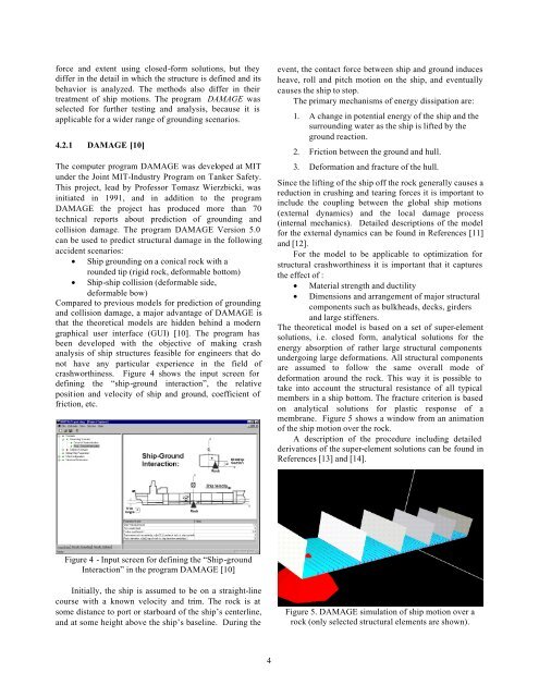
force <strong>and</strong> extent us<strong>in</strong>g closed-form solutions, but theydiffer <strong>in</strong> the detail <strong>in</strong> which the structure is def<strong>in</strong>ed <strong>and</strong> itsbehavior is analyzed. The methods also differ <strong>in</strong> theirtreatment of ship motions. The program DAMAGE wasselected for further test<strong>in</strong>g <strong>and</strong> analysis, because it isapplicable for a wider range of ground<strong>in</strong>g scenarios.4.2.1 DAMAGE [10]The computer program DAMAGE was developed at MITunder the Jo<strong>in</strong>t MIT-Industry Program on Tanker Safety.This project, lead by Professor Tomasz Wierzbicki, was<strong>in</strong>itiated <strong>in</strong> 1991, <strong>and</strong> <strong>in</strong> addition to the programDAMAGE the project has produced more than 70technical reports about prediction of ground<strong>in</strong>g <strong>and</strong>collision damage. The program DAMAGE Version 5.0can be used to predict structural damage <strong>in</strong> the follow<strong>in</strong>gaccident scenarios:• Ship ground<strong>in</strong>g on a conical rock with arounded tip (rigid rock, deformable bottom)• Ship-ship collision (deformable side,deformable bow)Compared to previous models for prediction of ground<strong>in</strong>g<strong>and</strong> collision damage, a major advantage of DAMAGE isthat the theoretical models are hidden beh<strong>in</strong>d a moderngraphical user <strong>in</strong>terface (GUI) [10]. The program hasbeen developed with the objective of mak<strong>in</strong>g crashanalysis of ship structures feasible for eng<strong>in</strong>eers that donot have any particular experience <strong>in</strong> the field ofcrashworth<strong>in</strong>ess. Figure 4 shows the <strong>in</strong>put screen fordef<strong>in</strong><strong>in</strong>g the “ship-ground <strong>in</strong>teraction”, the relativeposition <strong>and</strong> velocity of ship <strong>and</strong> ground, coefficient offriction, etc.event, the contact force between ship <strong>and</strong> ground <strong>in</strong>ducesheave, roll <strong>and</strong> pitch motion on the ship, <strong>and</strong> eventuallycauses the ship to stop.The primary mechanisms of energy dissipation are:1. A change <strong>in</strong> potential energy of the ship <strong>and</strong> thesurround<strong>in</strong>g water as the ship is lifted by theground reaction.2. Friction between the ground <strong>and</strong> hull.3. Deformation <strong>and</strong> fracture of the hull.S<strong>in</strong>ce the lift<strong>in</strong>g of the ship off the rock generally causes areduction <strong>in</strong> crush<strong>in</strong>g <strong>and</strong> tear<strong>in</strong>g forces it is important to<strong>in</strong>clude the coupl<strong>in</strong>g between the global ship motions(external dynamics) <strong>and</strong> the local damage process(<strong>in</strong>ternal mechanics). Detailed descriptions of the modelfor the external dynamics can be found <strong>in</strong> References [11]<strong>and</strong> [12].For the model to be applicable to optimization forstructural crashworth<strong>in</strong>ess it is important that it capturesthe effect of :• Material strength <strong>and</strong> ductility• Dimensions <strong>and</strong> arrangement of major structuralcomponents such as bulkheads, decks, girders<strong>and</strong> large stiffeners.The theoretical model is based on a set of super-elementsolutions, i.e. closed form, analytical solutions for theenergy absorption of rather large structural componentsundergo<strong>in</strong>g large deformations. All structural componentsare assumed to follow the same overall mode ofdeformation around the rock. This way it is possible totake <strong>in</strong>to account the structural resistance of all typicalmembers <strong>in</strong> a ship bottom. The fracture criterion is basedon analytical solutions for plastic response of amembrane. Figure 5 shows a w<strong>in</strong>dow from an animationof the ship motion over the rock.A description of the procedure <strong>in</strong>clud<strong>in</strong>g detailedderivations of the super-element solutions can be found <strong>in</strong>References [13] <strong>and</strong> [14].Figure 4 - Input screen for def<strong>in</strong><strong>in</strong>g the “Ship-groundInteraction” <strong>in</strong> the program DAMAGE [10]Initially, the ship is assumed to be on a straight-l<strong>in</strong>ecourse with a known velocity <strong>and</strong> trim. The rock is atsome distance to port or starboard of the ship’s centerl<strong>in</strong>e,<strong>and</strong> at some height above the ship’s basel<strong>in</strong>e. Dur<strong>in</strong>g theFigure 5. DAMAGE simulation of ship motion over arock (only selected structural elements are shown).4


