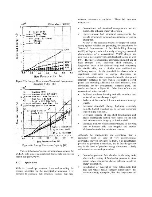
enhance resistance to collision. These fall <strong>in</strong>to twocategories:Figure 39 - Energy Absorption of <strong>Structural</strong> Components(St<strong>and</strong>ard VLCC) [40]Figure 40 - Energy Absorption Capacity [40]The contribution of various structural components fora ULCC with a more conventional double side structure isshown <strong>in</strong> Figure 39 [40].8.1.2 ApplicationWith the knowledge acquired from underst<strong>and</strong><strong>in</strong>g theprocess identified by the analytical evaluations, it ispossible to postulate hull structural features that may• Conventional hull structural arrangements that aremodified to enhance energy absorption.• Unconventional hull structural arrangements that<strong>in</strong>clude structurally actuated mechanisms for energyabsorption.As part of the research project for improved tankersafety aga<strong>in</strong>st collision <strong>and</strong> ground<strong>in</strong>g, the Association for<strong>Structural</strong> Improvement of the Shipbuild<strong>in</strong>g Industry(ASIS) of Japan conducted a study of vary<strong>in</strong>g structuralcharacteristics of a conventional VLCC design <strong>and</strong>apply<strong>in</strong>g a more unconventional structural feature as well[40]. The more conventional alterations <strong>in</strong>cluded use ofhigh strength steel, additional shell str<strong>in</strong>gers, alongitud<strong>in</strong>al strut <strong>in</strong> the outboard cargo tank support<strong>in</strong>gthe double side, <strong>and</strong> a double side unidirectionalstiffen<strong>in</strong>g system. As the side-shell has shown to be asignificant contributor to energy absorption, anunconventional new sk<strong>in</strong> composed of double plate panels<strong>in</strong>ternally stiffened by web frames, essentially a coredpanel sk<strong>in</strong> provid<strong>in</strong>g additional net shell thickness, wassubstituted for the conventional stiffened plate. Theresults are shown <strong>in</strong> Figure 40. Other ideas of the moreconventional nature <strong>in</strong>cluded:• Bulkhead stools on the w<strong>in</strong>g tank side to reduce hardspots <strong>and</strong> <strong>in</strong>crease damage length.• Reduced stiffness of web frames to <strong>in</strong>crease damagelength.• Increased side-shell plat<strong>in</strong>g thickness, especiallyfrom the ballast waterl<strong>in</strong>e up, to <strong>in</strong>crease membranetension <strong>in</strong> the side-shell.• Decreased spac<strong>in</strong>g of side-shell longitud<strong>in</strong>als <strong>and</strong>added <strong>in</strong>termediate vertical web frames on the sideshell to <strong>in</strong>crease the <strong>in</strong>tegrity of the side-shell.• Increased number of horizontal str<strong>in</strong>gers <strong>in</strong> the w<strong>in</strong>gtank to <strong>in</strong>crease side sk<strong>in</strong> <strong>in</strong>tegrity <strong>and</strong> provideadditional material for membrane tension.Although the practicability <strong>and</strong> acceptance from aregulatory po<strong>in</strong>t of view of very unconventionalapproaches may be seriously <strong>in</strong> doubt, it is neverthelesspossible to postulate alternatives, <strong>and</strong> <strong>in</strong> fact the greateststep <strong>in</strong> the level of possible energy absorption is likelywith an unconventional approaches:• Controlled pressure fluid chamber <strong>in</strong> the w<strong>in</strong>g tankswhere<strong>in</strong> the vent<strong>in</strong>g of fluid under pressure to otherspaces when compressed dur<strong>in</strong>g collision results <strong>in</strong>energy dissipation.• Introduction of material <strong>in</strong> w<strong>in</strong>g ballast-tanks thatdoes not reduce ballast capacity significantly, but<strong>in</strong>creases energy absorption, like ultra-large open-cell
foam. Permeability <strong>and</strong> <strong>in</strong>spection are possibleproblems with this approach.• Truss structure separat<strong>in</strong>g w<strong>in</strong>g tank sk<strong>in</strong>s. Such anarrangement can enhance the <strong>in</strong>tegrity of the <strong>in</strong>nerhull longer as the truss deforms while support<strong>in</strong>g theouter sk<strong>in</strong> <strong>and</strong> more slowly load<strong>in</strong>g the <strong>in</strong>ner sk<strong>in</strong>.• Pre-planned failure or “crumple zones” as have beendeveloped by the automobile <strong>in</strong>dustry for the morecritical <strong>and</strong> predictable areas of damage.• A foam release system actuated <strong>in</strong> the event of animpend<strong>in</strong>g collision with<strong>in</strong> the expected area ofcontact to <strong>in</strong>crease stiffness <strong>and</strong> energy absorption.8.2 Bow Impact8.2.1 Analytical IndicationsThe significance of the energy absorption <strong>in</strong> bow damage<strong>and</strong> the effects of the bow <strong>in</strong>teract<strong>in</strong>g with the struckship’s side structure make it a critical element <strong>in</strong>consider<strong>in</strong>g collision results. Calculations assum<strong>in</strong>g rigidbows with vertical stems <strong>and</strong> no bulbs have simplifiedanalyses <strong>and</strong> fostered underst<strong>and</strong><strong>in</strong>g, but do not depict thecurrent <strong>and</strong> likely future nature of bows. Ship resistance,power<strong>in</strong>g <strong>and</strong> seakeep<strong>in</strong>g requirements are likely tocont<strong>in</strong>ue to foster the existence of bows with raked stems<strong>and</strong> bulbs <strong>in</strong>to the future.Analytical evaluations do po<strong>in</strong>t a way to consider<strong>in</strong>gbows. If they are deformable, they will account for asizeable portion of the total energy absorption <strong>in</strong> acollision. If they can be made to deform <strong>in</strong> a manner thatdoes not cause premature failure of important struck shipenergy absorb<strong>in</strong>g structure, such as the side shell, then thesame attributes of a rigid vertical stem bow will beachieved at the struck vessel.8.3 ApplicationThe bows of ships <strong>in</strong>corporate a significant amount ofstiff horizontal fore <strong>and</strong> aft re<strong>in</strong>forc<strong>in</strong>g structural elementsthat enhance the rigidity of the structure. Alternatively,arrangements with transverse stiffen<strong>in</strong>g coupled withappropriate spac<strong>in</strong>g can lead to significant fold<strong>in</strong>gdeformation, which can effectively reduce or elim<strong>in</strong>atethe protrusions of the upper bow <strong>and</strong> bulb as well as theirstructural hard-spots. Recent studies [44] have confirmedthat lower crush<strong>in</strong>g pressure of a bulbous bow ispreferable to avoid the early rupture of the strucksideshell <strong>and</strong> the crush<strong>in</strong>g strength should not exceed thatof the side structure.8.4 Ground<strong>in</strong>g8.4.1 Analytical Indications – Ground<strong>in</strong>gThe potential phases of ground<strong>in</strong>g are depicted <strong>in</strong> Figure41. In ground<strong>in</strong>g <strong>and</strong> rak<strong>in</strong>g, the vessel has forwardspeed. In str<strong>and</strong><strong>in</strong>g it does not.Model test<strong>in</strong>g <strong>and</strong> computer f<strong>in</strong>ite element simulationof a str<strong>and</strong><strong>in</strong>g for a 280000 dwt tanker double bottomresulted <strong>in</strong> the lateral load versus <strong>in</strong>dentation of up to 2mshown <strong>in</strong> Figure 42. The peak po<strong>in</strong>t, po<strong>in</strong>t 1, denotes thebuckl<strong>in</strong>g of the center longitud<strong>in</strong>al girder, <strong>and</strong> po<strong>in</strong>t 2, thefracture of the outer bottom plat<strong>in</strong>g. Po<strong>in</strong>t 3 <strong>in</strong>dicatesfracture of the center girder-floor connection. It is<strong>in</strong>terest<strong>in</strong>g to note that the response shown <strong>in</strong> Figure 42 issimilar to that predicted for collision, with the pr<strong>in</strong>cipaldifference be<strong>in</strong>g the nature of the obtrusive load<strong>in</strong>g,which may be a l<strong>in</strong>e load for a collision <strong>and</strong> a po<strong>in</strong>t loadfor a ground<strong>in</strong>g.Rak<strong>in</strong>g bottom damage is of significantly differentcharacter than the ground<strong>in</strong>g damage heretoforediscussed. In rak<strong>in</strong>g damage, the obstruction ruptures thebottom structure <strong>and</strong> then cont<strong>in</strong>ues destructive shear<strong>in</strong>g,tear<strong>in</strong>g <strong>and</strong> buckl<strong>in</strong>g as the vessel cont<strong>in</strong>ues to move <strong>in</strong> itsdirection of motion, Figure 43. The length of bottomrak<strong>in</strong>g is based on an energy balance concept where thek<strong>in</strong>etic energy of the vessel is entirely absorbed by thedestruction of bottom structure.Figure 41 - Model of the ground<strong>in</strong>g process [41,42]An energy analysis for ground<strong>in</strong>g which takes <strong>in</strong>toaccount energy due to the tear<strong>in</strong>g that occurs dur<strong>in</strong>gtrack<strong>in</strong>g-type collisions presumes that <strong>in</strong> such cases thedamage will be long <strong>and</strong> shallow, <strong>in</strong>volv<strong>in</strong>g plate tear<strong>in</strong>g,but relatively little volume distortion of the <strong>in</strong>nerstructure. However, Figure 42 <strong>in</strong>dicates that if there is avertical component to the strik<strong>in</strong>g force, after fracture ofthe outer plat<strong>in</strong>g at po<strong>in</strong>t 2, there is an <strong>in</strong>crease <strong>in</strong> stiffnesslead<strong>in</strong>g up to po<strong>in</strong>t 3 <strong>and</strong> beyond as more girders <strong>and</strong>floors come <strong>in</strong>to contact with the obstruction. Figure 44also <strong>in</strong>dicates a retention of stiffness.23