

Structural Design and Response in Collision and Grounding
Structural Design and Response in Collision and Grounding
Structural Design and Response in Collision and Grounding

Create successful ePaper yourself
Turn your PDF publications into a flip-book with our unique Google optimized e-Paper software.
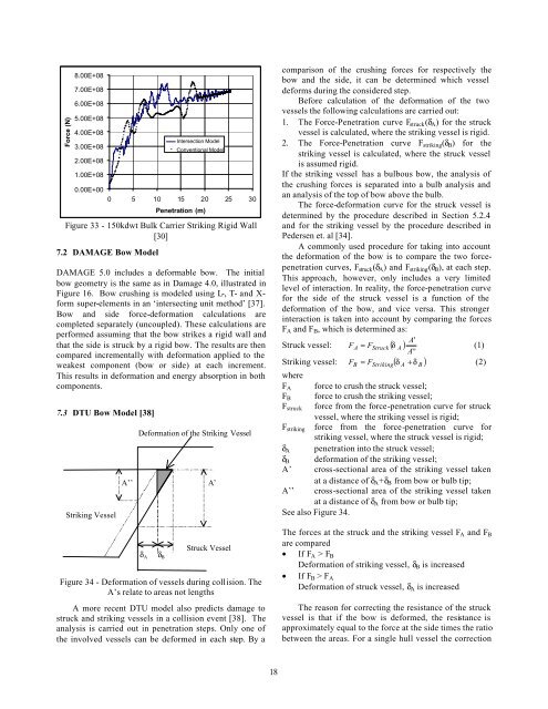
Force (N)8.00E+087.00E+086.00E+085.00E+084.00E+083.00E+082.00E+081.00E+08Intersection ModelConventional Model0.00E+000 5 10 15 20 25 30Penetration (m)Figure 33 - 150kdwt Bulk Carrier Strik<strong>in</strong>g Rigid Wall[30]7.2 DAMAGE Bow ModelDAMAGE 5.0 <strong>in</strong>cludes a deformable bow. The <strong>in</strong>itialbow geometry is the same as <strong>in</strong> Damage 4.0, illustrated <strong>in</strong>Figure 16. Bow crush<strong>in</strong>g is modeled us<strong>in</strong>g L-, T- <strong>and</strong> X-form super-elements <strong>in</strong> an ‘<strong>in</strong>tersect<strong>in</strong>g unit method’ [37].Bow <strong>and</strong> side force-deformation calculations arecompleted separately (uncoupled). These calculations areperformed assum<strong>in</strong>g that the bow strikes a rigid wall <strong>and</strong>that the side is struck by a rigid bow. The results are thencompared <strong>in</strong>crementally with deformation applied to theweakest component (bow or side) at each <strong>in</strong>crement.This results <strong>in</strong> deformation <strong>and</strong> energy absorption <strong>in</strong> bothcomponents.7.3 DTU Bow Model [38]Strik<strong>in</strong>g VesselDeformation of the Strik<strong>in</strong>g VesselA’’ A’comparison of the crush<strong>in</strong>g forces for respectively thebow <strong>and</strong> the side, it can be determ<strong>in</strong>ed which vesseldeforms dur<strong>in</strong>g the considered step.Before calculation of the deformation of the twovessels the follow<strong>in</strong>g calculations are carried out:1. The Force-Penetration curve F struck (δ A ) for the struckvessel is calculated, where the strik<strong>in</strong>g vessel is rigid.2. The Force-Penetration curve F strik<strong>in</strong>g (δ B ) for thestrik<strong>in</strong>g vessel is calculated, where the struck vesselis assumed rigid.If the strik<strong>in</strong>g vessel has a bulbous bow, the analysis ofthe crush<strong>in</strong>g forces is separated <strong>in</strong>to a bulb analysis <strong>and</strong>an analysis of the top of bow above the bulb.The force-deformation curve for the struck vessel isdeterm<strong>in</strong>ed by the procedure described <strong>in</strong> Section 5.2.4<strong>and</strong> for the strik<strong>in</strong>g vessel by the procedure described <strong>in</strong>Pedersen et. al [34].A commonly used procedure for tak<strong>in</strong>g <strong>in</strong>to accountthe deformation of the bow is to compare the two forcepenetrationcurves, F struck (δ A ) <strong>and</strong> F strik<strong>in</strong>g (δ B ), at each step.This approach, however, only <strong>in</strong>cludes a very limitedlevel of <strong>in</strong>teraction. In reality, the force-penetration curvefor the side of the struck vessel is a function of thedeformation of the bow, <strong>and</strong> vice versa. This stronger<strong>in</strong>teraction is taken <strong>in</strong>to account by compar<strong>in</strong>g the forcesF A <strong>and</strong> F B , which is determ<strong>in</strong>ed as:A'Struck vessel: FA= FStruck( δ A )(1)A''F = δ + δ(2)Strik<strong>in</strong>g vessel: ( )B F Strik<strong>in</strong>gwhereF A force to crush the struck vessel;F B force to crush the strik<strong>in</strong>g vessel;F struck force from the force-penetration curve for struckvessel, where the strik<strong>in</strong>g vessel is rigid;F strik<strong>in</strong>g force from the force-penetration curve forstrik<strong>in</strong>g vessel, where the struck vessel is rigid;δ A penetration <strong>in</strong>to the struck vessel;δ B deformation of the strik<strong>in</strong>g vessel;A’ cross-sectional area of the strik<strong>in</strong>g vessel takenat a distance of δ A +δ B from bow or bulb tip;A’’ cross-sectional area of the strik<strong>in</strong>g vessel takenat a distance of δ A from bow or bulb tip;See also Figure 34.ABδ Aδ BStruck VesselFigure 34 - Deformation of vessels dur<strong>in</strong>g collision. TheA’s relate to areas not lengthsA more recent DTU model also predicts damage tostruck <strong>and</strong> strik<strong>in</strong>g vessels <strong>in</strong> a collision event [38]. Theanalysis is carried out <strong>in</strong> penetration steps. Only one ofthe <strong>in</strong>volved vessels can be deformed <strong>in</strong> each step. By aThe forces at the struck <strong>and</strong> the strik<strong>in</strong>g vessel F A <strong>and</strong> F Bare compared• If F A > F BDeformation of strik<strong>in</strong>g vessel, δ B is <strong>in</strong>creased• If F B > F ADeformation of struck vessel, δ A is <strong>in</strong>creasedThe reason for correct<strong>in</strong>g the resistance of the struckvessel is that if the bow is deformed, the resistance isapproximately equal to the force at the side times the ratiobetween the areas. For a s<strong>in</strong>gle hull vessel the correction18


