

Structural Design and Response in Collision and Grounding
Structural Design and Response in Collision and Grounding
Structural Design and Response in Collision and Grounding

You also want an ePaper? Increase the reach of your titles
YUMPU automatically turns print PDFs into web optimized ePapers that Google loves.
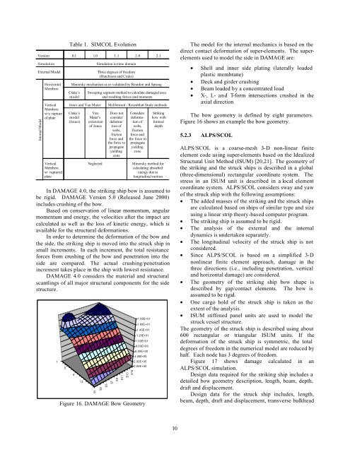
Table 1. SIMCOL EvolutionVersion 0.1 1.0 1.1 2.0 2.1SimulationExternal ModelInternal ModelHorizontalMembersVerticalMembersw/o ruptureof plateVerticalMembersw/ rupturedplateSimulation <strong>in</strong> time doma<strong>in</strong>Three degrees of freedom(Hutchison <strong>and</strong> Crake)M<strong>in</strong>orsky mechanism as re-validated by Reardon <strong>and</strong> SprungCrake’smodelJones <strong>and</strong> Van MaterCrake’smodel(Jones)Sweep<strong>in</strong>g segment method to calculate damaged area<strong>and</strong> result<strong>in</strong>g forces <strong>and</strong> momentsVanMater’sextensionof JonesNeglectedMcDermott / Rosenblatt Study methodsDoes notconsiderdeformationofwebs,frictionforce <strong>and</strong>the force topropagateyield<strong>in</strong>gzoneConsidersdeformationofwebs,frictionforce <strong>and</strong>the force topropagateyield<strong>in</strong>gzoneStrik<strong>in</strong>gbow withlimiteddepthM<strong>in</strong>orsky method forcalculat<strong>in</strong>g absorbedenergy due tolongitud<strong>in</strong>al motionIn DAMAGE 4.0, the strik<strong>in</strong>g ship bow is assumed tobe rigid. DAMAGE Version 5.0 (Released June 2000)<strong>in</strong>cludes crush<strong>in</strong>g of the bow.Based on conservation of l<strong>in</strong>ear momentum, angularmomentum <strong>and</strong> energy, the velocities after the impact arecalculated as well as the loss of k<strong>in</strong>etic energy, which isavailable for the structural deformations.In order to determ<strong>in</strong>e the deformation of the bow <strong>and</strong>the side, the strik<strong>in</strong>g ship is moved <strong>in</strong>to the struck ship <strong>in</strong>small <strong>in</strong>crements. In each <strong>in</strong>crement, the total resistanceforces from crush<strong>in</strong>g of the bow <strong>and</strong> penetration <strong>in</strong>to theside are compared. The actual crush<strong>in</strong>g/penetration<strong>in</strong>crement takes place <strong>in</strong> the ship with lowest resistance.DAMAGE 4.0 considers the material <strong>and</strong> structuralscantl<strong>in</strong>gs of all major structural components for the sidestructure.15913S1S3S5S7S9S11S13S151.80E+011.60E+011.40E+011.20E+011.00E+018.00E+006.00E+004.00E+002.00E+000.00E+00Figure 16. DAMAGE Bow GeometryThe model for the <strong>in</strong>ternal mechanics is based on thedirect contact deformation of super-elements. The superelementsused to model the side <strong>in</strong> DAMAGE are:• Shell <strong>and</strong> <strong>in</strong>ner side plat<strong>in</strong>g (laterally loadedplastic membrane)• Deck <strong>and</strong> girder crush<strong>in</strong>g• Beam loaded by a concentrated load• X-, L- <strong>and</strong> T-form <strong>in</strong>tersections crushed <strong>in</strong> theaxial directionThe bow geometry is def<strong>in</strong>ed by eight parameters.Figure 16 shows an example the bow geometry.5.2.3 ALPS/SCOLALPS/SCOL is a coarse-mesh 3-D non-l<strong>in</strong>ear f<strong>in</strong>iteelement code us<strong>in</strong>g super-elements based on the Idealized<strong>Structural</strong> Unit Method (ISUM) [20,21]. The geometry ofthe strik<strong>in</strong>g <strong>and</strong> the struck ships is described <strong>in</strong> a global(three-dimensional) rectangular coord<strong>in</strong>ate system. Thestress <strong>in</strong> an ISUM unit is described <strong>in</strong> a local elementcoord<strong>in</strong>ate system. ALPS/SCOL considers sway <strong>and</strong> yawof the struck ship with the follow<strong>in</strong>g assumptions:• The added masses of the strik<strong>in</strong>g <strong>and</strong> the struck shipsare calculated based on ships of similar type <strong>and</strong> sizeus<strong>in</strong>g a l<strong>in</strong>ear strip theory-based computer program.• The strik<strong>in</strong>g ship is assumed to be rigid.• The analysis of the external <strong>and</strong> the <strong>in</strong>ternaldynamics is undertaken separately.• The longitud<strong>in</strong>al velocity of the struck ship is notconsidered.• S<strong>in</strong>ce ALPS/SCOL is based on a simplified 3-Dnonl<strong>in</strong>ear f<strong>in</strong>ite element approach, damage <strong>in</strong> thethree directions (i.e., <strong>in</strong>clud<strong>in</strong>g penetration, vertical<strong>and</strong> horizontal damage) are considered.• The geometry of the strik<strong>in</strong>g ship bow shape isdescribed by gap/contact elements. The bow isassumed to be rigid.• One cargo hold of the struck ship is taken as theextent of the analysis.• ISUM stiffened panel units are used to model thestruck vessel structure.The geometry of the struck ship is described us<strong>in</strong>g about600 rectangular or triangular ISUM units. If thedeformation of the struck ship is symmetric, the totaldegrees of freedom <strong>in</strong> the numerical model are reduced byhalf. Each node has 3 degrees of freedom.Figure 17 shows damage calculated <strong>in</strong> anALPS/SCOL simulation.<strong>Design</strong> data required for the strik<strong>in</strong>g ship <strong>in</strong>cludes adetailed bow geometry description, length, beam, depth,draft <strong>and</strong> displacement.<strong>Design</strong> data for the struck ship <strong>in</strong>cludes, length,beam, depth, draft <strong>and</strong> displacement, transverse bulkhead10


