6.2 DATA FOR MODEL VALIDATIONThe second type of data required by the panel is for modelvalidation. In collision the follow<strong>in</strong>g data is required:• <strong>Collision</strong> Scenario• Strik<strong>in</strong>g ship• Speed• Displacement• Draft• Bow height• Type• <strong>Collision</strong> angle• Strike location• Struck ship design• L,B,D,T,∆• Speed• <strong>Structural</strong> design• h DB , w DS , y LBHD , x TBHD• web spac<strong>in</strong>g, z str<strong>in</strong>g , z strut• scantl<strong>in</strong>gs• Damage descriptionIn ground<strong>in</strong>g, the follow<strong>in</strong>g model validation data isrequired:• Ground<strong>in</strong>g Scenario• Geometry <strong>and</strong> elevation of the rock• Location of the rock relative to the ship'scenterl<strong>in</strong>e• Ship speed, draft, displacement <strong>and</strong> trim• Grounded ship design• Hull type (s<strong>in</strong>gle hull, double hull, mid -deck, …)• L, B, D, LCG, LCF, GM T , GM L• Waterplane area• Transverse <strong>and</strong> longitud<strong>in</strong>al bulkhead locations• Frame spac<strong>in</strong>g, spac<strong>in</strong>g of longitud<strong>in</strong>al girders• Scantl<strong>in</strong>gs• Damage description7 STRIKING SHIP BOW7.1 SIMCOL Bow Model StudyAll of the collision models used thus far <strong>in</strong> this study, <strong>and</strong>most models used by other researchers, assume that thestrik<strong>in</strong>g ship bow is rigid. This is chang<strong>in</strong>g. Panel work<strong>in</strong> this area is focused on the follow<strong>in</strong>g questions <strong>and</strong>problems:1. Is the rigid bow assumption rational? Is significantenergy absorbed by the strik<strong>in</strong>g ship bow? Is thisenergy variable <strong>in</strong> different collision scenarios?2. If bow deformation is important, can this problem besolved uncoupled from the side damage problem?3. Identify a simple, but sufficient bow model for futureuse <strong>in</strong> SIMCOL.4. Develop a course-mesh bow model to speed upLSDYNA model<strong>in</strong>g for SIMCOL validation.Most collision accidents that result <strong>in</strong> significantstruck ship damage also result <strong>in</strong> significant damage tothe strik<strong>in</strong>g ship bow. M<strong>in</strong>orsky’s orig<strong>in</strong>al analysis [26]considered absorbed energy <strong>in</strong> the strik<strong>in</strong>g bow. Areanalysis of his data <strong>in</strong>dicates that absorbed bow energy<strong>in</strong> these cases accounted for between 8 <strong>and</strong> 53 percent ofthe total absorbed energy [30]. More recent studies byReckl<strong>in</strong>g [31], Akita <strong>and</strong> Kitamura [32], <strong>and</strong> Valsgard <strong>and</strong>Pettersen [33] <strong>in</strong>dicate absorbed bow energies <strong>in</strong> the rangeof 42 to 55 percent of the total absorbed energy.LSDYNA analyses conducted at Virg<strong>in</strong>ia Tech withdeformable bows <strong>and</strong> sides show absorbed bow energies<strong>in</strong> the range of 22 to 44 percent [30]. We mu st concludethat absorbed bow energy can be significant <strong>and</strong> variable,<strong>and</strong> therefore should be considered <strong>in</strong> collision analyses.The availability of this data is extremely limited.Accident data from USCG databases for the period of1980-1998 was screened for sufficiency <strong>and</strong> applicabilityto this problem. Useful validation cases must <strong>in</strong>clude allof the data specified above (scenario, structural design,damage description). In the case of collision, thefollow<strong>in</strong>g additional criteria were applied:• Strik<strong>in</strong>g location <strong>in</strong> struck ship away from bow orstern.• <strong>Collision</strong> angles of 45-135 degrees.• Penetration greater than one meter.Collection <strong>and</strong> evaluation of this data is also ongo<strong>in</strong>g.Table 6. Bow Model Test Matrix16
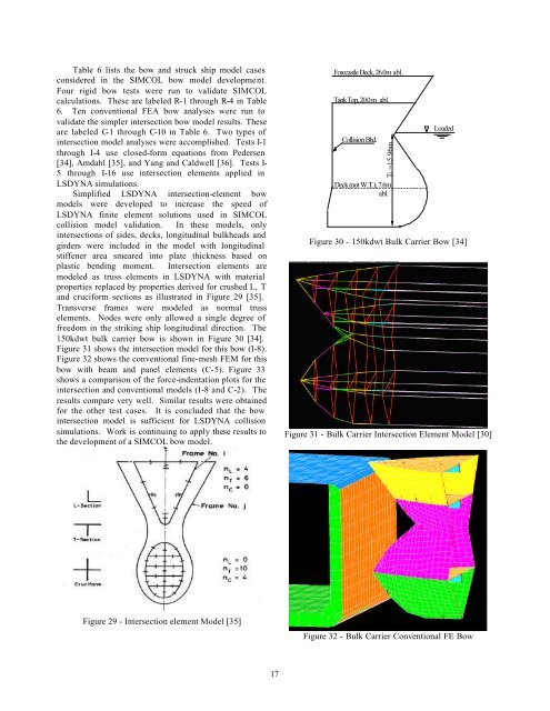
Table 6 lists the bow <strong>and</strong> struck ship model casesconsidered <strong>in</strong> the SIMCOL bow model development.Four rigid bow tests were run to validate SIMCOLcalculations. These are labeled R-1 through R-4 <strong>in</strong> Table6. Ten conventional FEA bow analyses were run tovalidate the simpler <strong>in</strong>tersection bow model results. Theseare labeled C-1 through C-10 <strong>in</strong> Table 6. Two types of<strong>in</strong>tersection model analyses were accomplished. Tests I-1through I-4 use closed-form equations from Pedersen[34], Amdahl [35], <strong>and</strong> Yang <strong>and</strong> Caldwell [36]. Tests I-5 through I-16 use <strong>in</strong>tersection elements applied <strong>in</strong>LSDYNA simulations.Simplified LSDYNA <strong>in</strong>tersection-element bowmodels were developed to <strong>in</strong>crease the speed ofLSDYNA f<strong>in</strong>ite element solutions used <strong>in</strong> SIMCOLcollision model validation. In these models, only<strong>in</strong>tersections of sides, decks, longitud<strong>in</strong>al bulkheads <strong>and</strong>girders were <strong>in</strong>cluded <strong>in</strong> the model with longitud<strong>in</strong>alstiffener area smeared <strong>in</strong>to plate thickness based onplastic bend<strong>in</strong>g moment. Intersection elements aremodeled as truss elements <strong>in</strong> LSDYNA with materialproperties replaced by properties derived for crushed L, T<strong>and</strong> cruciform sections as illustrated <strong>in</strong> Figure 29 [35].Transverse frames were modeled as normal trusselements. Nodes were only allowed a s<strong>in</strong>gle degree offreedom <strong>in</strong> the strik<strong>in</strong>g ship longitud<strong>in</strong>al direction. The150kdwt bulk carrier bow is shown <strong>in</strong> Figure 30 [34].Figure 31 shows the <strong>in</strong>tersection model for this bow (I-8).Figure 32 shows the conventional f<strong>in</strong>e-mesh FEM for thisbow with beam <strong>and</strong> panel elements (C-5). Figure 33shows a comparison of the force-<strong>in</strong>dentation plots for the<strong>in</strong>tersection <strong>and</strong> conventional models (I-8 <strong>and</strong> C-2). Theresults compare very well. Similar results were obta<strong>in</strong>edfor the other test cases. It is concluded that the bow<strong>in</strong>tersection model is sufficient for LSDYNA collisionsimulations. Work is cont<strong>in</strong>u<strong>in</strong>g to apply these results tothe development of a SIMCOL bow model.Forecastle Deck, 26.0m abl.Tank Top, 20.0 m abl.<strong>Collision</strong> Bhd.Tl =15.96mDeck (not W.T.), 7.6mabl.LoadedFigure 30 - 150kdwt Bulk Carrier Bow [34]Figure 31 - Bulk Carrier Intersection Element Model [30]Figure 29 - Intersection element Model [35]Figure 32 - Bulk Carrier Conventional FE Bow17