

Structural Design and Response in Collision and Grounding
Structural Design and Response in Collision and Grounding
Structural Design and Response in Collision and Grounding

You also want an ePaper? Increase the reach of your titles
YUMPU automatically turns print PDFs into web optimized ePapers that Google loves.
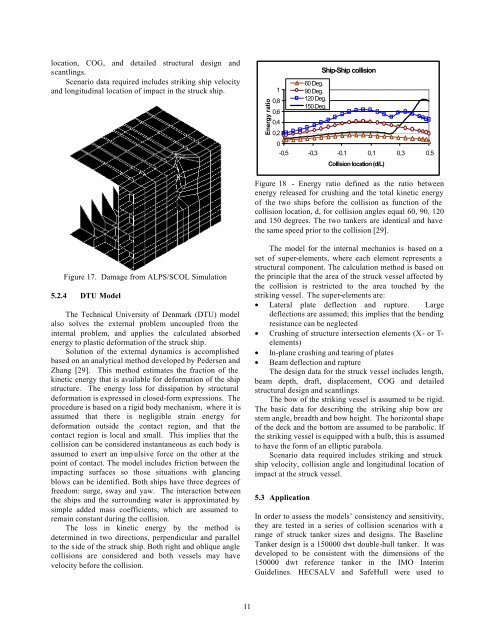
location, COG, <strong>and</strong> detailed structural design <strong>and</strong>scantl<strong>in</strong>gs.Scenario data required <strong>in</strong>cludes strik<strong>in</strong>g ship velocity<strong>and</strong> longitud<strong>in</strong>al location of impact <strong>in</strong> the struck ship.Energy ratio10,80,60,40,260 Deg.90 Deg.120 Deg.150 Deg.Ship-Ship collision0-0,5 -0,3 -0,1 0,1 0,3 0,5<strong>Collision</strong> location (d/L)Figure 18 - Energy ratio def<strong>in</strong>ed as the ratio betweenenergy released for crush<strong>in</strong>g <strong>and</strong> the total k<strong>in</strong>etic energyof the two ships before the collision as function of thecollision location, d, for collision angles equal 60, 90, 120<strong>and</strong> 150 degrees. The two tankers are identical <strong>and</strong> havethe same speed prior to the collision [29].Figure 17. Damage from ALPS/SCOL Simulation5.2.4 DTU ModelThe Technical University of Denmark (DTU) modelalso solves the external problem uncoupled from the<strong>in</strong>ternal problem, <strong>and</strong> applies the calculated absorbedenergy to plastic deformation of the struck ship.Solution of the external dynamics is accomplishedbased on an analytical method developed by Pedersen <strong>and</strong>Zhang [29]. This method estimates the fraction of thek<strong>in</strong>etic energy that is available for deformation of the shipstructure. The energy loss for dissipation by structuraldeformation is expressed <strong>in</strong> closed-form expressions. Theprocedure is based on a rigid body mechanism, where it isassumed that there is negligible stra<strong>in</strong> energy fordeformation outside the contact region, <strong>and</strong> that thecontact region is local <strong>and</strong> small. This implies that thecollision can be considered <strong>in</strong>stantaneous as each body isassumed to exert an imp ulsive force on the other at thepo<strong>in</strong>t of contact. The model <strong>in</strong>cludes friction between theimpact<strong>in</strong>g surfaces so those situations with glanc<strong>in</strong>gblows can be identified. Both ships have three degrees offreedom: surge, sway <strong>and</strong> yaw. The <strong>in</strong>teraction betweenthe ships <strong>and</strong> the surround<strong>in</strong>g water is approximated bysimple added mass coefficients, which are assumed torema<strong>in</strong> constant dur<strong>in</strong>g the collision.The loss <strong>in</strong> k<strong>in</strong>etic energy by the method isdeterm<strong>in</strong>ed <strong>in</strong> two directions, perpendicular <strong>and</strong> parallelto the side of the struck ship. Both right <strong>and</strong> oblique anglecollisions are considered <strong>and</strong> both vessels may havevelocity before the collision.The model for the <strong>in</strong>ternal mechanics is based on aset of super-elements, where each element represents astructural component. The calculation method is based onthe pr<strong>in</strong>ciple that the area of the struck vessel affected bythe collision is restricted to the area touched by thestrik<strong>in</strong>g vessel. The super-elements are:• Lateral plate deflection <strong>and</strong> rupture. Largedeflections are assumed; this implies that the bend<strong>in</strong>gresistance can be neglected• Crush<strong>in</strong>g of structure <strong>in</strong>tersection elements (X- or T-elements)• In-plane crush<strong>in</strong>g <strong>and</strong> tear<strong>in</strong>g of plates• Beam deflection <strong>and</strong> ruptureThe design data for the struck vessel <strong>in</strong>cludes length,beam depth, draft, displacement, COG <strong>and</strong> detailedstructural design <strong>and</strong> scantl<strong>in</strong>gs.The bow of the strik<strong>in</strong>g vessel is assumed to be rigid.The basic data for describ<strong>in</strong>g the strik<strong>in</strong>g ship bow arestem angle, breadth <strong>and</strong> bow height. The horizontal shapeof the deck <strong>and</strong> the bottom are assumed to be parabolic. Ifthe strik<strong>in</strong>g vessel is equipped with a bulb, this is assumedto have the form of an elliptic parabola.Scenario data required <strong>in</strong>cludes strik<strong>in</strong>g <strong>and</strong> struckship velocity, collision angle <strong>and</strong> longitud<strong>in</strong>al location ofimpact at the struck vessel.5.3 ApplicationIn order to assess the models’ consistency <strong>and</strong> sensitivity,they are tested <strong>in</strong> a series of collision scenarios with arange of struck tanker sizes <strong>and</strong> designs. The Basel<strong>in</strong>eTanker design is a 150000 dwt double-hull tanker. It wasdeveloped to be consistent with the dimensions of the150000 dwt reference tanker <strong>in</strong> the IMO InterimGuidel<strong>in</strong>es. HECSALV <strong>and</strong> SafeHull were used to11


