

Download - O Scale Trains Magazine Online
Download - O Scale Trains Magazine Online
Download - O Scale Trains Magazine Online
- No tags were found...

Create successful ePaper yourself
Turn your PDF publications into a flip-book with our unique Google optimized e-Paper software.
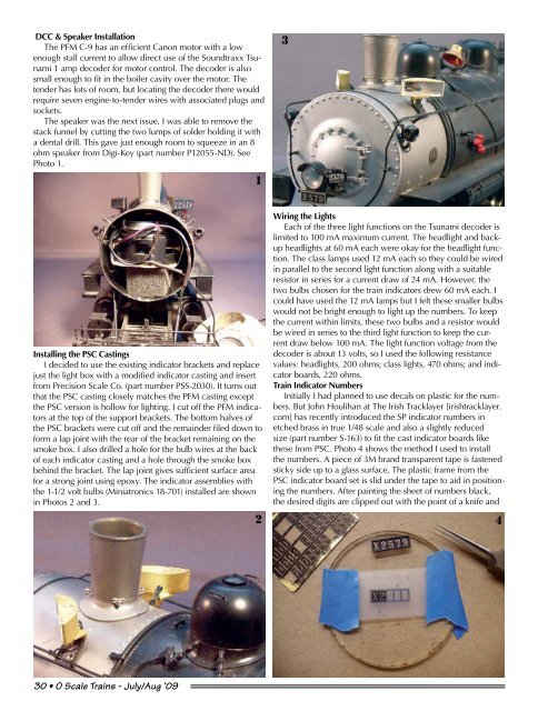
DCC & Speaker InstallationThe PFM C-9 has an efficient Canon motor with a lowenough stall current to allow direct use of the Soundtraxx Tsunami1 amp decoder for motor control. The decoder is alsosmall enough to fit in the boiler cavity over the motor. Thetender has lots of room, but locating the decoder there wouldrequire seven engine-to-tender wires with associated plugs andsockets.The speaker was the next issue. I was able to remove thestack funnel by cutting the two lumps of solder holding it witha dental drill. This gave just enough room to squeeze in an 8ohm speaker from Digi-Key (part number P12055-ND). SeePhoto 1.13Installing the PSC CastingsI decided to use the existing indicator brackets and replacejust the light box with a modified indicator casting and insertfrom Precision <strong>Scale</strong> Co. (part number PSS-2030). It turns outthat the PSC casting closely matches the PFM casting exceptthe PSC version is hollow for lighting. I cut off the PFM indicatorsat the top of the support brackets. The bottom halves ofthe PSC brackets were cut off and the remainder filed down toform a lap joint with the rear of the bracket remaining on thesmoke box. I also drilled a hole for the bulb wires at the backof each indicator casting and a hole through the smoke boxbehind the bracket. The lap joint gives sufficient surface areafor a strong joint using epoxy. The indicator assemblies withthe 1-1/2 volt bulbs (Miniatronics 18-701) installed are shownin Photos 2 and 3.2Wiring the LightsEach of the three light functions on the Tsunami decoder islimited to 100 mA maximum current. The headlight and backupheadlights at 60 mA each were okay for the headlight function.The class lamps used 12 mA each so they could be wiredin parallel to the second light function along with a suitableresistor in series for a current draw of 24 mA. However, thetwo bulbs chosen for the train indicators drew 60 mA each. Icould have used the 12 mA lamps but I felt these smaller bulbswould not be bright enough to light up the numbers. To keepthe current within limits, these two bulbs and a resistor wouldbe wired in series to the third light function to keep the currentdraw below 100 mA. The light function voltage from thedecoder is about 13 volts, so I used the following resistancevalues: headlights, 200 ohms; class lights, 470 ohms; and indicatorboards, 220 ohms.Train Indicator NumbersInitially I had planned to use decals on plastic for the numbers.But John Houlihan at The Irish Tracklayer [irishtracklayer.com] has recently introduced the SP indicator numbers inetched brass in true 1/48 scale and also a slightly reducedsize (part number S-163) to fit the cast indicator boards likethese from PSC. Photo 4 shows the method I used to installthe numbers. A piece of 3M brand transparent tape is fastenedsticky side up to a glass surface. The plastic frame from thePSC indicator board set is slid under the tape to aid in positioningthe numbers. After painting the sheet of numbers black,the desired digits are clipped out with the point of a knife and430 • O <strong>Scale</strong> <strong>Trains</strong> - July/Aug ’09


