Download 33kv Copper Cables Brochure - Prysmian
Download 33kv Copper Cables Brochure - Prysmian
Download 33kv Copper Cables Brochure - Prysmian
- No tags were found...
You also want an ePaper? Increase the reach of your titles
YUMPU automatically turns print PDFs into web optimized ePapers that Google loves.
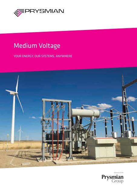
Medium VoltageYOUR ENERGY, OUR SYSTEMS, ANYWHERE
IntroductionONE LEADER, TWO BRANDSThe world’s largest cable company, the <strong>Prysmian</strong>Group, consists of <strong>Prysmian</strong> and Draka which are twoof the world’s most respected commercial brands inthe industry. With subsidiaries in 50 countries, almost100 manufacturing plants, 17 Research & DevelopmentCentres and around 22,000 employees, the <strong>Prysmian</strong>Group is truly a global company.Proudly manufacturing in Australia since 1940, <strong>Prysmian</strong>understands local standards and conditions and ourproducts are designed and developed accordingly.<strong>Prysmian</strong> specialises in integrated, added valuecabling solutions highly customised to the individualspecifications of customers. <strong>Prysmian</strong> operates aQuality Management System compliant with therequirements of ISO 9001:2008 and products are fullysupported by the global technical and productioncapabilities of the <strong>Prysmian</strong> Group.<strong>Prysmian</strong> understands localstandards and conditions andour products are designed anddeveloped accordingly.3
Cable ComponentsTHIS MANUAL CONTAINS TECHNICAL INFORMATIONON A WIDE VARIETY OF COMMONLY USED MEDIUMVOLTAGE (MV) POWER CABLES MANUFACTURED TOAUSTRALIAN STANDARD AS/NZS 1429.1.Full constructional and technical details are given for<strong>Prysmian</strong>’s standard range of MV power cables. Otherconstructions and variants are available by special order.For standard industrial applications, XLPE insulation isnormally recommended, but for situations where thecable may be continuously subject to wet conditions,the well proven resistance of <strong>Prysmian</strong>’s EPR compoundoffers additional security. Both insulation systems havebeen assessed for long term resistance to water underthe two year UNIPEDE test regime and successfully metthe criteria. <strong>Prysmian</strong>’s EPR compound has also met therequirements of more onerous long term tests.The standard oversheaths supplied are either BLACKPVC (5V-90) or a combination of layers of PVC and HDPEto AS/NZS 1429.1, AS/NZS 4026 and AS/NZS 3808.For situations where limiting the emission of smokeand corrosive gases from cables affected by fire isdesirable, the use of <strong>Prysmian</strong>’s LSOH HFS-90TP sheathto AS/NZS 3808 is recommended. These cables areconstructionally and dimensionally the same as AS/NZS1429.1 cables and employ the same insulation systemsbut with LSOH sheaths. The tabulated data in thistechnical manual is valid irrespective of the sheathingoption.High-density polyethylene sheath (HDPE) can besupplied where greater impermeability to moisture andgreater resistance to abrasion is required for adverseinstallation conditions, but such sheaths are notrecommended in areas of fire risk.Where protection against termites and other invasiveinsects is required, cables can be supplied with acovering of Nylon 12, or with two helically applied brassor stainless steel tapes. Alternatively <strong>Prysmian</strong> offerTermitex covering as a protection against termites.For protection against rodents, <strong>Prysmian</strong> recommendthe use of armour or steel tapes. Brass or coppertapes provide only limited protection against rodentsand specifiers need to be aware of the risk for eachinstallation.4
CABLE COMPONENTS<strong>Prysmian</strong> offers a choice of two standard screen sizesfor different earth fault requirements for EPR andXLPE cables. For systems with small earth fault levels alight duty screen is offered for protection based on thescreens having a nominal short-circuit rating of 3 kA forone second. For systems with high fault levels, a heavydutyscreen is available with a nominal short-circuitrating of 10 kA for one second.i.) Light-duty Screened <strong>Cables</strong> are for use in circuitsprotected by fast acting devices such as HRC fuses orsystems having low I 2 t earth fault values.ii.) Heavy-duty Screened <strong>Cables</strong> are designed to carryhigh earth fault currents comparable with systemsymmetrical fault currents. They are designed for supplysystems having high I 2 t earth fault values.For three core cables, one third of the required screeningis nominated for each core, the fault current beingassumed to be shared by all screens. The one-secondearth fault current ratings are given in the data sheetsfor each of the medium voltage XLPE and EPR cables.faced by Utilities and Contractors in power distribution.The company provides a cable design service capableof servicing your requirements for power cablespecification. <strong>Prysmian</strong> innovation has led to newproducts including:• New concepts for protection of cable from termitesbacked by sponsored CSIRO research.• Alternative solutions to armour for protection of cablesfrom impact damage.• EPR COMPACT medium voltage cables have beendeveloped for cost-effective replacement of networksusing existing ductwork. These cables have beendesigned to optimise electrical and mechanicalproperties in dimensionally smaller cables. This hasbeen accomplished through use of the EPRotenaxPremium Performance insulation system, whichcombines maximum current carrying capacity with arugged outer sheath and sufficient insulation thicknessto deliver the same reliable service as the paper cablesbeing replaced.These standard screens can be varied to suit individualsystem fault requirements. <strong>Prysmian</strong> has manyalternative solutions to meet the demanding problems<strong>Prysmian</strong> can also advise on various tree-retardantinsulations and water blocking options.5
CABLE COMPONENTSDESIGNATIONSEach cable type is identified by a reference typedesignation for ease of reference and a full orderdesignation which fully identifies each cable and shouldbe used on order documentation. <strong>Cables</strong> are metremarked for ease of installation and inventory control.All cables are listed with the voltage rating for which thecable is designed, expressed in the form Uo/U, where Uois the nominal voltage between conductor(s) and earthand U is the nominal voltage between phase conductors.RECOMMENDED USEThe cables described in this technical manual aredesigned to be used for the supply of electrical energy infixed installations up to the indicated rated voltage at anominal power frequency in the range 49Hz to 61Hz.<strong>Cables</strong> to AS/NZS 1429.1 and AS/NZS 4026 areintended for use either installed in air, directly buriedin the ground or in ducts. <strong>Cables</strong> with LSOH sheathhave improved fire performance when installed inair and are primarily intended for such locations.Reasonable protection against mechanical damageshould be provided.<strong>Cables</strong> in this technical manual are not specificallydesigned for use as self-supporting aerial cables, assubmarine cables, where exposure to excessive heator corrosive products or solvent substances is involved.In case of any doubt concerning the suitability of aparticular cable type for a particular use, guidanceshould be sought from <strong>Prysmian</strong>’s CustomerService Centre.6
Cable HandlingCable Usage CharacteristicsAMBIENT TEMPERATUREMaximum operating temperatureMinimum operating temperatureMINIMUM BENDING RADIUSMinimum bending radius of installed cablesMECHANICAL IMPACT RESISTANCE1 Light Impact2 Moderate Impact3 Heavy Impact4 Very Heavy ImpactRESISTANCE TO SOLAR RADIATION AND WEATHERExcellent PermanentVery Good FrequentGoodOccasionalAcceptable AccidentalPoorNoneBEHAVIOUR IN FLAME AND FIREReaction To Fire Resistant To FireC 1 Fire retardant Level 1 Ultimate fire survivalC 2 Flame retardant Level 2 Two hours fire survivalC 3 No fire performance Level 3 Restrained spread &self extinguishingHALOGEN FREEAS/NZS 4507CHEMICAL RESISTANCEExcellent PermanentVery Good FrequentGoodOccasionalAcceptable AccidentalPoorNoneRESISTANCE TO WATERNegligible No humidityWater Drops Occasional condensationSprayWater run offSplashesExposed to water splashesHeavy Sea Exposed to wavesImmersion Temporarily covered by waterSubmersion Permanently covered by waterFLEXIBILITYRigidSemi-rigidLOW SMOKE EMISSIONAS/NZS 4507FlexibleVery flexibleLaying ConditionsMINIMUM BENDINGRADIUS DURINGINSTALLATIONIN TRENCH IN GROUND IN DUCT DOMESTICAPPLIANCESMACHINESMOBILEEQUIPMENTSUBMERGEDOVERHEAD AERIALMINIMUMINSTALLATIONTEMPERATUREIN FREE AIRIN GROUND WITHPROTECTIONIN CONDUITOUTDOORAPPLIANCESFESTOONINTERNALWIRINGINDUSTRIALEQUIPMENTEXTERNALBUILDING7
Product CodesConductor Nominal Cross Sectional Area25, 35, 50, 70, 95, 120, 150, 185, 240, 300, 400, 500, 630Single or Three core1C, 3CConductor Material<strong>Copper</strong> – CU, Aluminium – ALInsulation MaterialXLPE – X, EPR – EkV Rating3–1.9/3.3, 6–3.8/6.6, 11–6.35/11, 22–12.7/22, 33–19/33Screen TypeLight Duty – LD, Heavy Duty – HDArmouringArmoured – A, Unarmoured – blank95 3C CU X 11 LD ACSAPRODUCT CODEEXAMPLE:95mm 2 three core, copper conductor, XLPE insulated, 11kV, light duty screen, armoured.When ordering, please quote the conductor nominal cross sectional area ahead of theproduct code which appears on each data sheet.8
Health, Safety and EnvironmentPEOPLE ARE OUR GREATEST ASSET. WE BELIEVEEVERYONE HAS THE RIGHT TO WORK AND LIVE IN AHEALTHY AND SAFE ENVIRONMENT.The <strong>Prysmian</strong> Group maintains our commitment tocomply with all relevant Occupational Health, Safety andEnvironmental legislation, Australian and New ZealandStandards (AS/NZS 4801 and ISO 14001) Licences andIndustry Codes of Practices.Our goal is an environmentally and socially sustainablebusiness and we believe that a safe work environmentis a sign of efficiency and quality. Accidents can beprevented and we commit to continually improve, toachieve zero incidents of work related injury, illness andenvironmental pollution.We also aim to help our customers fulfil theirenvironmental responsibilities by providing them withcables and associated products that we believe havebeen manufactured as efficiently, economically soundand environmentally sustainable as possible. As ourproducts are locally designed and manufactured werecognize the importance of risk assessment andmitigation in all mining operations.For additional support in this area we have dedicatedtechnical staff available to provide specific productinformation and guidelines for use please contact:sales.au@prysmiangroup.com9
Exploded Cable ViewSINGLE COREStraded compactedcopper or aluminium conductorSemi-conductive conductor screenXLPE insulation<strong>Copper</strong> wire screenPVC sheathTHREE COREStraded compactedcopper or aluminium conductorSemi-conductive conductor screenXLPE insulation<strong>Copper</strong> wire screenFiltersPVC sheath11
MEDIUM VOLTAGE CABLES<strong>Copper</strong>19/33kVSINGLE CORE LIGHT DUTY SCREENED UNARMOUREDCable CharacteristicsSemi-rigid12D (PVC only)15D (HDPE)1 (PVC only)3 (HDPE)Spray (XPLE)Immersion (EPR)Good+90˚C-25˚CC3AcceptableCable DesignCONDUCTOR:Plain circular compacted copperMaximum Continuous Operating Temperature: 90°CCONDUCTOR SCREEN:Extruded semi-conducting compound, bonded to the insulation and applied in the same operation as the insulationINSULATION:Cross Linked Polyethylene (XLPE) – standardEthylene Propylene Rubber (EPR) – alternativeINSULATION SCREEN:Extruded, semi-conductive compoundMETALLIC SCREEN:Plain annealed copper wire: 3kA for nominal 1 secondSHEATH:Black 5V-90 polyvinyl chloride (PVC) – standardOrange 5V-90 PVC inner plus black high density polyethylene (HDPE) outer – alternativeLow smoke zero halogen (LSOH) – alternativeInstallation ConditionsIN FREE AIRIN DUCTIN TRENCHIN GROUNDIN GROUND WITHPROTECTION18D (PVC only)25D (HDPE)108
MEDIUM VOLTAGE CABLES<strong>Copper</strong>19/33kVPhysical & Electrical CharacteristicsProduct Code1CCUX33LDNominal ConductorArea mm 2 50 70 95 120 150 185 240 300 400 500 630Nominal ConductorDiameter mmNominal InsulationThickness mmApprox CableDiameter mm8.2 9.8 11.5 12.9 14.3 16.1 18.2 20.6 23.5 26.6 30.38.0 8.0 8.0 8.0 8.0 8.0 8.0 8.0 8.0 8.0 8.033.1 34.7 36.6 38.0 39.6 41.4 43.8 46.5 50.2 53.5 57.4Approx Mass kg/100m 140 165 195 225 255 295 355 420 515 625 770Max Pulling TensionOn Conductor kNMax Pulling TensionOn Stocking Grip kNMin Bending Radius*:During Installation mmMin Bending Radius*:Set In Position mmMax ConductorResistance, dc @ 20°COhm/kmConductor Resistance,ac @ 90°C & 50 HzOhm/kmInductance, TrefoilTouching mH/kmInductive Reactance,Trefoil Touching@ 50Hz Ohm/kmZero Seq. Impedance@ 20°C & 50 HzOhm/kmCapacitance, PhaseTo Earth µF/kmMin InsulationResistance @ 20°CMOhm.kmElectric Stress AtConductor ScreenkV/mmCharging Current @Rated Voltage & 50 HzA/phase/kmShortCircuitRatingContinuousCurrentRatingPhaseConductorkA, 1 secMetallicScreenkA, 1 secIn Ground,Direct BuriedAIn Ground,In SinglewayDuctsAIn Free Air,Unenclosed& SpacedFrom WallA3.5 4.9 6.7 8.4 11 13 17 21 25 25 253.5 4.2 4.7 5.1 5.5 6.0 6.7 7.6 8.8 10 12600 630 660 680 710 740 790 840 900 960 1030400 420 440 460 480 500 530 560 600 640 6900.387 0.268 0.193 0.153 0.124 0.0991 0.0754 0.0601 0.0470 0.0366 0.02830.494 0.342 0.247 0.196 0.159 0.127 0.0976 0.0786 0.0625 0.0500 0.04050.507 0.469 0.447 0.428 0.415 0.400 0.385 0.372 0.359 0.346 0.3350.159 0.147 0.140 0.134 0.130 0.126 0.121 0.117 0.113 0.109 0.1051.32+j0.09751.20+j0.08681.13+j0.08021.09+j0.07491.06+j0.07111.03+j0.06701.01+j0.06270.995+j0.05910.982+j0.05560.973+j0.05210.965+j0.04910.139 0.155 0.170 0.183 0.196 0.212 0.231 0.254 0.284 0.312 0.34418,000 16,000 15,000 14,000 13,000 12,000 11,000 9,900 8,800 8,000 7,2004.07 3.85 3.67 3.55 3.46 3.36 3.26 3.16 3.06 2.99 2.930.831 0.923 1.02 1.09 1.17 1.26 1.38 1.52 1.70 1.86 2.067.2 10.0 13.6 17.2 21.5 26.5 34.3 42.9 57.2 71.5 90.13.0 3.0 3.0 3.0 3.0 3.0 3.0 3.0 3.0 3.0 3.0205 250 300 335 380 425 490 555 625 705 795200 245 290 325 360 405 465 520 585 655 735220 275 330 380 435 495 580 665 770 885 1015The cables described in this technical manual are designed to be used for the supply of electrical energy in fixed applications up to the rated voltages at a nominal power frequency between 49Hz and 61Hz.*Increased radius required for HDPE and nylon incorporating designs.109
MEDIUM VOLTAGE CABLES<strong>Copper</strong>19/33kVSINGLE CORE HEAVY DUTY SCREENED UNARMOUREDCable CharacteristicsSemi-rigid12D (PVC only)15D (HDPE)1 (PVC only)3 (HDPE)Spray (XPLE)Immersion (EPR)Good+90˚C-25˚CC3AcceptableCable DesignCONDUCTOR:Plain circular compacted copperMaximum Continuous Operating Temperature: 90°CCONDUCTOR SCREEN:Extruded semi-conducting compound, bonded to the insulation and applied in the same operation as the insulationINSULATION:Cross Linked Polyethylene (XLPE) – standardEthylene Propylene Rubber (EPR) – alternativeINSULATION SCREEN:Extruded semi-conducting compoundMETALLIC SCREEN:Plain annealed copper wire: 10kA for nominal 1 secondSHEATH:Black 5V-90 polyvinyl chloride (PVC) – standardOrange 5V-90 PVC inner plus black high density polyethylene (HDPE) outer – alternativeLow smoke zero halogen (LSOH) – alternativeInstallation ConditionsIN FREE AIRIN DUCTIN TRENCHIN GROUNDIN GROUND WITHPROTECTION18D (PVC only)25D (HDPE)110
MEDIUM VOLTAGE CABLES<strong>Copper</strong>19/33kVPhysical & Electrical CharacteristicsProduct Code1CCUX33HDNominal ConductorArea mm 2 50 70 95 120 150 185 240 300 400 500 630Nominal ConductorDiameter mmNominal InsulationThickness mmApprox CableDiameter mm8.2 9.8 11.5 12.9 14.3 16.1 18.2 20.6 23.5 26.6 30.38.0 8.0 8.0 8.0 8.0 8.0 8.0 8.0 8.0 8.0 8.034.4 36.2 37.9 39.5 40.9 42.9 45.1 47.8 51.5 54.8 58.7Approx Mass kg/100m 165 210 240 270 300 340 400 465 560 675 815Max Pulling TensionOn Conductor kNMax Pulling TensionOn Stocking Grip kNMin Bending Radius*:During Installation mmMin Bending Radius*:Set In Position mmMax ConductorResistance, dc @ 20°COhm/kmConductor Resistance,ac @ 90°C & 50 HzOhm/kmInductance, TrefoilTouching mH/kmInductive Reactance,Trefoil Touching@ 50Hz Ohm/kmZero Seq. Impedance@ 20°C & 50 HzOhm/kmCapacitance, PhaseTo Earth µF/kmMin InsulationResistance @ 20°CMOhm.kmElectric Stress AtConductor ScreenkV/mmCharging Current @Rated Voltage & 50 HzA/phase/kmShortCircuitRatingContinuousCurrentRatingPhaseConductorkA, 1 secMetallicScreenkA, 1 secIn Ground,Direct BuriedAIn Ground,In SinglewayDuctsAIn Free Air,Unenclosed& SpacedFrom WallA3.5 4.9 6.7 8.4 11 13 17 21 25 25 253.5 4.6 5.0 5.5 5.9 6.4 7.1 8.0 9.3 10 12620 650 680 710 740 770 810 860 930 990 1060410 430 460 470 490 510 540 570 620 660 7000.387 0.268 0.193 0.153 0.124 0.0991 0.0754 0.0601 0.0470 0.0366 0.02830.494 0.342 0.247 0.196 0.159 0.127 0.0976 0.0785 0.0624 0.0500 0.04040.515 0.478 0.454 0.436 0.422 0.407 0.391 0.378 0.365 0.352 0.3400.162 0.150 0.143 0.137 0.133 0.128 0.123 0.119 0.115 0.110 0.1070.783+j0.09890.550+j0.08810.475+j0.08150.435+j0.07620.406+j0.07230.381+j0.06810.358+j0.06380.343+j0.06010.330+j0.05660.320+j0.05300.312+j0.04990.139 0.155 0.170 0.183 0.196 0.212 0.231 0.254 0.284 0.312 0.34418,000 16,000 15,000 14,000 13,000 12,000 11,000 9,900 8,800 8,000 7,2004.07 3.85 3.67 3.55 3.46 3.36 3.26 3.16 3.06 2.99 2.930.831 0.923 1.02 1.09 1.17 1.26 1.38 1.52 1.70 1.86 2.067.2 10.0 13.6 17.2 21.5 26.5 34.3 42.9 57.2 71.5 90.17.1 10 10 10 10 10 10 10 10 10 10205 250 295 335 370 420 480 535 605 675 750200 235 275 310 340 375 425 470 520 575 630220 275 335 380 430 490 575 655 750 855 970The cables described in this technical manual are designed to be used for the supply of electrical energy in fixed applications up to the rated voltages at a nominal power frequency between 49Hz and 61Hz.*Increased radius required for HDPE and nylon incorporating designs.111
MEDIUM VOLTAGE CABLES<strong>Copper</strong>19/33kVTHREE CORE LIGHT DUTY SCREENED UNARMOUREDCable CharacteristicsSemi-rigid12D (PVC only)15D (HDPE)1 (PVC only)3 (HDPE)Spray (XPLE)Immersion (EPR)Good+90˚C-25˚CC3AcceptableCable DesignCONDUCTOR:Plain circular compacted copperMaximum Continuous Operating Temperature: 90°CCONDUCTOR SCREEN:Extruded semi-conducting compound, bonded to the insulation and applied in the same operation as the insulationINSULATION:Cross Linked Polyethylene (XLPE) – standardEthylene Propylene Rubber (EPR) – alternativeINSULATION SCREEN:Extruded semi-conducting compoundMETALLIC SCREEN:Plain annealed copper wire: 3kA for nominal 1 secondSHEATH:Black 5V-90 polyvinyl chloride (PVC) – standardOrange 5V-90 PVC inner plus black high density polyethylene (HDPE) outer – alternativeLow smoke zero halogen (LSOH) – alternativeInstallation ConditionsIN FREE AIRIN DUCTIN TRENCHIN GROUNDIN GROUND WITHPROTECTION18D (PVC only)25D (HDPE)112
MEDIUM VOLTAGE CABLES<strong>Copper</strong>19/33kVPhysical & Electrical CharacteristicsProduct Code3CCUX33LDNominal ConductorArea mm 2 50 70 95 120 150 185 240 300Nominal ConductorDiameter mmNominal InsulationThickness mmApprox CableDiameter mm8.2 9.8 11.5 12.9 14.3 16.1 18.2 20.68.0 8.0 8.0 8.0 8.0 8.0 8.0 8.068.5 72.4 76.3 79.5 82.7 86.7 91.8 97.6Approx Mass kg/100m 435 525 620 715 810 940 1140 1350Max Pulling TensionOn Conductors kNMax Pulling TensionOn Stocking Grip kNMin Bending Radius*:During Installation mmMin Bending Radius*:Set In Position mmMax ConductorResistance, dc @ 20°COhm/kmConductor Resistance,ac @ 90°C & 50 HzOhm/km11 15 20 25 25 25 25 2511 15 20 22 24 25 25 251230 1300 1370 1430 1490 1560 1650 1760820 870 920 950 990 1040 1100 11700.387 0.268 0.193 0.153 0.124 0.0991 0.0754 0.06010.494 0.342 0.247 0.196 0.159 0.128 0.0978 0.0788Inductance mH/km 0.457 0.422 0.401 0.384 0.371 0.358 0.344 0.332Inductive Reactance,@ 50Hz Ohm/kmZero Seq. Impedance@ 20°C & 50 HzOhm/kmCapacitance, PhaseTo Earth µF/kmMin InsulationResistance @ 20°CMOhm.kmElectric Stress AtConductor ScreenkV/mmCharging Current @Rated Voltage & 50 HzA/phase/kmShortCircuitRatingContinuousCurrentRatingPhaseConductorkA, 1 secMetallicScreenkA, 1 secIn Ground,Direct BuriedAIn Ground,In SinglewayDuctsAIn Free Air,Unenclosed& SpacedFrom WallA0.143 0.133 0.126 0.121 0.117 0.112 0.108 0.1042.32+j0.0978 2.09+j0.0871 1.92+j0.0805 1.79+j0.0752 1.69+j0.0714 1.59+j0.0672 1.44+j0.0629 1.37+j0.05930.140 0.155 0.171 0.184 0.197 0.212 0.232 0.25518,000 16,000 15,000 14,000 13,000 12,000 11,000 9,9004.07 3.85 3.67 3.55 3.46 3.36 3.26 3.160.834 0.927 1.02 1.10 1.17 1.27 1.39 1.527.2 10.0 13.6 17.2 21.5 26.5 34.3 42.94.3 4.6 4.8 5.1 5.3 5.6 6.1 6.3190 235 280 320 365 410 484 545170 210 245 280 310 355 401 452195 245 295 340 390 440 544 620The cables described in this technical manual are designed to be used for the supply of electrical energy in fixed applications up to the rated voltages at a nominal power frequency between 49Hz and 61Hz.*Increased radius required for HDPE and nylon incorporating designs.113
MEDIUM VOLTAGE CABLES<strong>Copper</strong>19/33kVTHREE CORE LIGHT DUTY SCREENED ARMOUREDCable CharacteristicsSemi-rigid12D (PVC only)15D (HDPE)1 (PVC only)3 (HDPE)3 (Armoured)Spray (XPLE)Immersion (EPR)Good+90˚C-25˚CC3AcceptableCable DesignCONDUCTOR:Plain circular compacted copperMaximum Continuous Operating Temperature: 90°CCONDUCTOR SCREEN:Extruded semi-conducting compound, bonded to the insulation and applied in the same operation as the insulationINSULATION:Cross Linked Polyethylene (XLPE) – standardEthylene Propylene Rubber (EPR) – alternativeINSULATION SCREEN:Extruded semi-conducting compoundMETALLIC SCREEN:Plain annealed copper wire: 3kA for nominal 1 secondARMOURING:Galvanised steel wiresSHEATH:Black 5V-90 polyvinyl chloride (PVC) – standardOrange 5V-90 PVC inner plus black high density polyethylene (HDPE) outer – alternativeLow smoke zero halogen (LSOH) – alternativeInstallation ConditionsIN FREE AIRIN DUCTIN TRENCHIN GROUNDIN GROUND WITHPROTECTION18D (PVC only)25D (HDPE)114
MEDIUM VOLTAGE CABLES<strong>Copper</strong>19/33kVPhysical & Electrical CharacteristicsProduct Code3CCUX33LDANominal ConductorArea mm 2 50 70 95 120 150Nominal ConductorDiameter mmNominal InsulationThickness mmApprox CableDiameter mm8.2 9.8 11.5 12.9 14.38.0 8.0 8.0 8.0 8.079.9 84.1 88.0 91.4 94.8Approx Mass kg/100m 920 1040 1160 1280 1400Max Pulling TensionOn Conductors kNMax Pulling TensionOn Stocking Grip kNMax Pulling TensionOn Amour Wires kNMin Bending Radius*:During Installation mmMin Bending Radius*:Set In Position mmMax ConductorResistance, dc @ 20°COhm/kmConductor Resistance,ac @ 90°C & 50 HzOhm/km11 15 20 25 2511 15 20 25 2525 25 25 25 251440 1510 1580 1640 1710960 1010 1060 1100 11400.387 0.268 0.193 0.153 0.1240.494 0.342 0.247 0.196 0.159Inductance mH/km 0.457 0.422 0.401 0.384 0.371Inductive Reactance,@ 50Hz Ohm/kmZero Seq. Impedance@ 20°C & 50 HzOhm/kmCapacitance, PhaseTo Earth µF/kmMin InsulationResistance @ 20°CMOhm.kmElectric Stress AtConductor ScreenkV/mmCharging Current @Rated Voltage & 50 HzA/phase/kmShortCircuitRatingContinuousCurrentRatingPhaseConductorkA, 1 secMetallicScreenkA, 1 secIn Ground,Direct BuriedAIn Ground,In SinglewayDuctsAIn Free Air,Unenclosed& SpacedFrom WallA0.143 0.133 0.126 0.121 0.1172.32+j0.0978 2.09+j0.0871 1.92+j0.0805 1.79+j0.0752 1.69+j0.07140.140 0.155 0.171 0.184 0.19718,000 16,000 15,000 14,000 13,0004.07 3.85 3.67 3.55 3.460.834 0.927 1.02 1.10 1.177.2 10.0 13.6 17.2 21.54.3 4.6 4.8 5.1 5.3190 235 280 320 365170 210 245 280 310195 245 295 340 390The cables described in this technical manual are designed to be used for the supply of electrical energy in fixed applications up to the rated voltages at a nominal power frequency between 49Hz and 61Hz.*Increased radius required for HDPE and nylon incorporating designs.115
MEDIUM VOLTAGE CABLES<strong>Copper</strong>19/33kVTHREE CORE HEAVY DUTY SCREENED UNARMOUREDCable CharacteristicsSemi-rigid12D (PVC only)15D (HDPE)1 (PVC only)3 (HDPE)Spray (XPLE)Immersion (EPR)Good+90˚C-25˚CC3AcceptableCable DesignCONDUCTOR:Plain circular compacted copperMaximum Continuous Operating Temperature: 90°CCONDUCTOR SCREEN:Extruded semi-conducting compound, bonded to the insulation and applied in the same operation as the insulationINSULATION:Cross Linked Polyethylene (XLPE) – standardEthylene Propylene Rubber (EPR) – alternativeINSULATION SCREEN:Extruded semi-conducting compoundMETALLIC SCREEN:Plain annealed copper wire: 10kA for nominal 1 secondSHEATH:Black 5V-90 polyvinyl chloride (PVC) – standardOrange 5V-90 PVC inner plus black high density polyethylene (HDPE) outer – alternativeLow smoke zero halogen (LSOH) – alternativeInstallation ConditionsIN FREE AIRIN DUCTIN TRENCHIN GROUNDIN GROUND WITHPROTECTION18D (PVC only)25D (HDPE)116
MEDIUM VOLTAGE CABLES<strong>Copper</strong>19/33kVPhysical & Electrical CharacteristicsProduct Code3CCUX33HDNominal ConductorArea mm 2 50 70 95 120 150 185 240 300Nominal ConductorDiameter mmNominal InsulationThickness mmApprox CableDiameter mm8.2 9.8 11.5 12.9 14.3 16.1 18.2 20.68.0 8.0 8.0 8.0 8.0 8.0 8.0 8.068.7 72.4 76.3 79.5 82.7 86.7 91.8 97.6Approx Mass kg/100m 455 560 655 745 840 970 1160 1380Max Pulling TensionOn Conductors kNMax Pulling TensionOn Stocking Grip kNMin Bending Radius*:During Installation mmMin Bending Radius*:Set In Position mmMax ConductorResistance, dc @ 20°COhm/kmConductor Resistance,ac @ 90°C & 50 HzOhm/km11 15 20 25 25 25 25 2511 15 20 22 24 25 25 251240 1300 1370 1430 1490 1560 1650 1760820 870 920 950 990 1040 1100 11700.387 0.268 0.193 0.153 0.124 0.0991 0.0754 0.06010.494 0.342 0.247 0.196 0.159 0.128 0.0978 0.0788Inductance mH/km 0.457 0.422 0.401 0.384 0.371 0.358 0.344 0.332Inductive Reactance,@ 50Hz Ohm/kmZero Seq. Impedance@ 20°C & 50 HzOhm/kmCapacitance, PhaseTo Earth µF/kmMin InsulationResistance @ 20°CMOhm.kmElectric Stress AtConductor ScreenkV/mmCharging Current @Rated Voltage & 50 HzA/phase/kmShortCircuitRatingContinuousCurrentRatingPhaseConductorkA, 1 secMetallicScreenkA, 1 secIn Ground,Direct BuriedAIn Ground,In SinglewayDuctsAIn Free Air,Unenclosed& SpacedFrom WallA0.143 0.133 0.126 0.121 0.117 0.112 0.108 0.1041.56+j0.0978 1.11+j0.0871 1.03+j0.0805 0.995+j0.0752 0.966+j0.0714 0.941+j0.0672 0.917+j0.0629 0.902+j0.05930.140 0.155 0.171 0.184 0.197 0.212 0.232 0.25518,000 16,000 15,000 14,000 13,000 12,000 11,000 9,9004.07 3.85 3.67 3.55 3.46 3.36 3.26 3.160.834 0.927 1.02 1.10 1.17 1.27 1.39 1.527.2 10.0 13.6 17.2 21.5 26.5 34.3 42.97.1 10 10 10 10 10 10 10195 240 285 330 370 410 486 547170 210 250 280 320 360 402 452195 250 305 350 395 450 550 627The cables described in this technical manual are designed to be used for the supply of electrical energy in fixed applications up to the rated voltages at a nominal power frequency between 49Hz and 61Hz.*Increased radius required for HDPE and nylon incorporating designs.117
MEDIUM VOLTAGE CABLES<strong>Copper</strong>19/33kVTHREE CORE HEAVY DUTY SCREENED ARMOUREDCable CharacteristicsSemi-rigid12D (PVC only)15D (HDPE)1 (PVC only)3 (HDPE)3 (Armoured)Spray (XPLE)Immersion (EPR)Good+90˚C-25˚CC3AcceptableCable DesignCONDUCTOR:Plain circular compacted copperMaximum Continuous Operating Temperature: 90°CCONDUCTOR SCREEN:Extruded semi-conducting compound, bonded to the insulation and applied in the same operation as the insulationINSULATION:Cross Linked Polyethylene (XLPE) – standardEthylene Propylene Rubber (EPR) – alternativeINSULATION SCREEN:Extruded semi-conducting compoundMETALLIC SCREEN:Plain annealed copper wire: 10kA for nominal 1 secondARMOURING:Galvanised steel wiresSHEATH:Black 5V-90 polyvinyl chloride (PVC) – standardOrange 5V-90 PVC inner plus black high density polyethylene (HDPE) outer – alternativeLow smoke zero halogen (LSOH) – alternativeInstallation ConditionsIN FREE AIRIN DUCTIN TRENCHIN GROUNDIN GROUND WITHPROTECTION18D (PVC only)25D (HDPE)118
MEDIUM VOLTAGE CABLES<strong>Copper</strong>19/33kVPhysical & Electrical CharacteristicsProduct Code3CCUX33HDANominal ConductorArea mm 2 50 70 95 120 150Nominal ConductorDiameter mmNominal InsulationThickness mmApprox CableDiameter mm8.2 9.8 11.5 12.9 14.38.0 8.0 8.0 8.0 8.080.1 84.1 88.0 91.4 94.8Approx Mass kg/100m 940 1070 1190 1310 1430Max Pulling TensionOn Conductors kNMax Pulling TensionOn Stocking Grip kNMax Pulling TensionOn Amour Wires kNMin Bending Radius*:During Installation mmMin Bending Radius*:Set In Position mmMax ConductorResistance, dc @ 20°COhm/kmConductor Resistance,ac @ 90°C & 50 HzOhm/km11 15 20 25 2511 15 20 25 2525 25 25 25 251440 1510 1580 1640 1710960 1010 1060 1100 11400.387 0.268 0.193 0.153 0.1240.494 0.342 0.247 0.196 0.159Inductance mH/km 0.457 0.422 0.401 0.384 0.371Inductive Reactance,@ 50Hz Ohm/kmZero Seq. Impedance@ 20°C & 50 HzOhm/kmCapacitance, PhaseTo Earth µF/kmMin InsulationResistance @ 20°CMOhm.kmElectric Stress AtConductor ScreenkV/mmCharging Current @Rated Voltage & 50 HzA/phase/kmShortCircuitRatingContinuousCurrentRatingPhaseConductorkA, 1 secMetallicScreenkA, 1 secIn Ground,Direct BuriedAIn Ground,In SinglewayDuctsAIn Free Air,Unenclosed& SpacedFrom WallA0.143 0.133 0.126 0.121 0.1171.56+j0.0978 1.11+j0.0871 1.03+j0.0805 0.995+j0.0752 0.966+j0.07140.140 0.155 0.171 0.184 0.19718,000 16,000 15,000 14,000 13,0004.07 3.85 3.67 3.55 3.460.834 0.927 1.02 1.10 1.177.2 10.0 13.6 17.2 21.57.1 10 10 10 10195 240 285 330 370170 210 250 280 320195 250 305 350 395The cables described in this technical manual are designed to be used for the supply of electrical energy in fixed applications up to the rated voltages at a nominal power frequency between 49Hz and 61Hz.*Increased radius required for HDPE and nylon incorporating designs.119
Technical InformationCABLE SELECTION<strong>Cables</strong> should be selected and used such that theproduct does not present an unacceptable risk or dangerto life or property when used in its intended manner.<strong>Cables</strong> should also be selected so that they are suitablefor the operating environment conditions e.g. use inpetrochemical works, need for fire performance, theneed for protection against attack by rodents, termites,etc, equipment classification and any other externalinfluences which may exist.They should also be selected according to theappropriate rated voltage and the cross-sectional areaof every conductor such that its current carrying capacityis not less than the maximum sustained current whichwould normally flow through it, and the short circuitcurrent rating of conductor and screen is adequatefor the prospective short circuit and time for which itpersists.In addition, consideration should be given to otherrelevant factors, such as:• voltage drop requirements• operating characteristics of connected equipment• economicsENVIRONMENTAL PROTECTIONThe standard cable finishes are adequate for normalenvironmental conditions. However, there are manyinstallations where conditions are much more onerousthan normal and some brief notes for protectionof cables against hostile environments are givenbelow. Once the type of protective covering to meetenvironmental conditions has been decided, it isgenerally possible taking voltage and current ratingsinto account, to arrive at the type of cable insulation tobe used.OIL REFINERIES AND CHEMICAL PLANTSPolymeric and elastomeric cables are not compatiblewith hydrocarbon oils and organic solvents. Such oilsand solvents particularly at elevated temperatures areabsorbed by the insulation and sheathing materialsleading to swelling and resultant damage.For casual contact with oil spills, a Nitrile or CSP rubbersheath can be used.PVC sheaths offer good protection against chemicalattack. Specifiers should contact <strong>Prysmian</strong> forrecommendations regarding the protection of cablesagainst harsh chemical environments.TERMITES, TEREDOES & RODENTSSpecial constructions are necessary to resist insectssuch as termites, as all cables with normal finishes aresusceptible to their attack. If cables are installed inlocations where termite attack is likely, protection maytake the form of one of the following:• Two helically applied brass tapes, the upper oneoverlapping the gap in the lower one, may beincorporated into the cable design. In the case ofarmoured cable the brass tapes may be applied underthe bedding of the armour. For unarmoured cable thebrass tapes can be applied over the normal PVC orother extruded sheath followed by a PVC sheath overthe brass tapes.• A nylon jacket may be applied over the PVC or otherextruded sheath followed by a sacrificial layer ofextruded PVC over the nylon to protect it from damageduring installation.• Termitex technology incorporated into the cabledesign, for long term protection.Chemical treatment of the backfill is no longerrecommended because of damage to the environmentand the risk to health.The teredo worm is prevalent in tropical, subtropical andtemperate oceans and estuaries. Protection is usuallyattained by incorporating two brass tapes under thearmour of all submarine cables.In areas liable to attack by rodents, galvanised steelwire armour provides an effective barrier. A layer ofnylon covering under the armour provides additionalprotection from insects.<strong>Prysmian</strong> have expertise in designing cables to resistboring insect and rodent attack. Please call theCustomer Service Team for advice.Semi-conductive components on high voltage cablesmay lose their conductive properties. It follows thatwhere polymeric and elastomeric cables are used inlocations where exposure to hydrocarbon oils andorganic solvents is likely, a lead sheath is required. Themost satisfactory protection for the lead sheath wouldbe a high density polyethylene sheath with steel wirearmour.132
TECHNICAL INFORMATIONEXPOSURE TO MECHANICAL DAMAGE1. Slight exposure to impact and to tensile stresses.The application of a high density polyethylenesheath can give appreciable added mechanicalprotection to cables with the normal PVC sheath.This method is suitable for single and multi-corecables.2. Moderate exposure to impact and to tensilestresses. Single core cables can be armouredwith non-ferrous armour wire, usually hard drawnaluminium. For Multicore cables a single layer ofgalvanised steel wire armour is recommended.The steel wire is necessary if there is likely to be amoderate tensile stress applied to the cable duringpulling in or during service. Steel wire armouredcables offer good protection against ruggedinstallation conditions.3. Severe exposure to impact and tensile stresses.The double wire armour finish offers a very high levelof protection against mechanical damage whetherit be impact or longitudinal tensile stress such as insubsidence areas and submarine installations on anuneven sea floor.4. Polymeric protection against impact.<strong>Prysmian</strong> developed AIRBAG, which providesenhanced mechanical/impact protection keepingthe handling and installation characteristics ofunprotected cables.EXPOSURE TO ULTRA VIOLET RADIATION<strong>Prysmian</strong> has special materials designed to preventUV degradation when exposed to sunlight. To be surethe correct material is used it is necessary to state atthe time of enquiry and ordering that the cable will beexposed to sunlight.FIRE SITUATIONSThe performance of a cable in a fire situation can be amajor factor in the choice of cable type. When correctlyselected, located and installed cables do not present afire hazard but in the case of fire initiated elsewhere,cables provide a source of fuel and a possible means ofpropagation along its length.Additionally cables can contribute to the emission ofsmoke and noxious gases injurious to equipment andhuman health. Evolution of smoke can reduce visibility,which can cause panic and create serious problems inevacuating personnel. The presence of acid gas in thesmoke can result in corrosion, damage of electronic andother equipment and can cause intense irritation to theeyes and lungs.<strong>Cables</strong> manufactured from PVC and some othertraditional materials when exposed to fire will producedense black smoke and harmful fumes and maypropagate fire when installed in bundles. Where thesefactors are of concern, the use of LSOH sheathed cablesis recommended.On the basis of standards in current use, cables can bedivided into the following categories in relation to theirbehaviour in the presence of fire:Flame propagation (single cable) – when tested singly,the cable should self-extinguish within a short periodof time and within a short distance from the point ofapplication of a Bunsen burner flame. Such cables meetAS/NZS 1660.5.6 and IEC 60332 Part 1 and are oftencalled flame retardant. Such cables will not necessarilyprevent propagation along bunches of cables installedtogether on vertical racks and exposed to a large-scalefire source.Flame propagation (cable bunches) – when testedinstalled in defined bunches on a vertical ladder, thecables should not propagate flame more than a limiteddistance from the point of application of a ribbon burnerflame front. Such cables meet AS/NZS 1660.5.1 and IEC60332 Part 3 and are often called reduced propagation.Three categories exist in AS/NZS 1660.5.1 according tothe volume of combustible material tested, CategoryA (7 l/m), Category B (3.5 l/m) and Category C (1.5l/m). It should however be noted that propagation offire is often a function of installation conditions andappropriate care should be taken to ensure that the testcategory chosen is representative of the actual installedcondition.Low smoke zero halogen cables – have controlled limitson smoke evolution when cable samples are burnt in aclosed 3m cube smoke chamber and controlled limitson acidic and corrosive gases when subject to materialpyrolysis in a tube furnace. Such cables meet AS/NZS1660.5.2 (IEC 61034) for smoke emission and AS/NZS1660.5.4 (IEC 754-2) for determination of degree ofacidity by measurement of pH and conductivity and areoften called LSOH.By nature of their typical intended use the MV powercables of this type may be used where the performanceof the cable in case of fire is important, either forlimitation of the propagation of flame along cablebunches or the limitation of smoke and corrosive gasemissions.Reduced flame propagation variants of all cables inthis technical manual can be supplied LSOH sheathsfor situations where limiting the emission of smokeand corrosive gas from the cables if affected by fire isdesirable.133
TECHNICAL INFORMATIONVOLTAGE RATINGIt is important to know whether the system to which thecable is connected is classified as earthed or unearthed.Supply authority systems are generally, though notalways, earthed design. Mining systems are usually theunearthed design. <strong>Prysmian</strong> products are suitable forvoltages that are commonly used in Australia. Voltage isusually expressed in the form Uo/U and Um.Uo is the rms power frequency voltage between phaseand earth.U is the rms power frequency voltage between phases.Um is the maximum continuous rms power frequencyvoltage between any two phases for which the cable isdesigned. It excludes momentary variations due to faultconditions or sudden disconnection of large loads.CABLE VOLTAGESGeneral <strong>Cables</strong>Uo/UkVRated Voltages of <strong>Cables</strong>Mining <strong>Cables</strong>Uo/UkVMax Continuous Operating VoltageUmkV1.9/3.3 3.3/3.3 3.63.8/6.6 6.6/6.6 7.26.35/11 11/11 1212.7/22 22/22 2419/33 33/33 3638/66 72The selection of standard cables for particular supplysystems depends on the system voltage and earthingarrangements.Category A – system in which any phase conductor thatcomes in contact with earth or an earth conductor isdisconnected from the system within 1 minute.Category B – system which, under fault conditions, isoperated for a short time with one phase earthed, notexceeding 8 hours on any occasion and total duration ofearth faults in any year not exceeding 125 hours.Category C – system which does not fall into CategoriesA and B.CABLE SELECTIONMax System Voltage(Um) kVNote: If an earth fault is not automatically and promptlyisolated, the extra stresses on the cable insulationduring the fault reduce the life of the cable to a certaindegree. If the system is expected to be operated fairlyoften with a permanent earth fault, it may be advisableto classify the system in Category C.Category A & BMin Rated (Phase to Earth)Voltage of Cable (Uo) kVCategory C3.6 1.9 3.87.2 3.8 6.3512.0 6.35 12.724.0 12.7 1936.0 19 -134
TECHNICAL INFORMATIONCURRENT RATINGSThe current ratings indicated in this manual have beenbased on the calculation procedures as recommendedin IEC 60287 and the following assumptions. Ratingfactors should be applied to cover any variation.• Max. continuous conductor temp. = 90°C• Ambient air temperature = 40°C• Ambient ground temperature = 25°C• Depth of laying = 0.8m• Thermal resistivity of soil = 1.2°C.m/W• Balanced load, comprising either a single three corecable or three single core cables, in trefoil formationtouching throughout, with the screens bonded at bothends of the route.• Installation conditions:1. Direct Buried:<strong>Cables</strong> are installed direct in the ground, withsuitable compacted backfill2. Buried Singleway Ducts:<strong>Cables</strong> are installed with one cable per duct3. In Free Air:<strong>Cables</strong> installed shielded from direct sunlight andwith a minimum clearance from any vertical wallof 0.3xCable Dia. and 0.5xCable Dia. for single andthree core cables respectively to ensure free aircirculation.In order to select the appropriate cable for a givenapplication, consideration must be given to the natureof the installation. It is not possible to provide adefinitive guide to specifying the correct cable typefor every situation, this choice must be made by thespecifier and/or installer based upon a knowledgeof the installation, applicable regulations and thecharacteristics of available cable designs. Generalguidance on the use of cable types included has beengiven above, but for further information and guidance itis recommended to make reference to the appropriatecable standard (e.g. AS/NZS 1429.1 or AS/NZS 4026).TEMPERATURE LIMITSIn respect of thermal effects the temperature limit givenfor each cable type is the maximum temperature due toany combination of the heating effect of current in theconductors and ambient conditions. All insulation andsheathing materials become stiffer as their temperatureis lowered and due regard has been taken of this factorin the guidance on minimum installation temperature.The materials used for these cables are compatible withtemperatures of 90ºC for continuous operation and250ºC for short circuit conditions of up to 5 seconds.The fault ratings for the conductors and the metallicscreens are provided for a time period of 1 second. Whenother times (t) between 0.2 and 5 seconds are required,the appropriate rating may be obtained by multiplyingthe 1 second rating by the factor: 1/√t.The ratings for the screens are based upon thetraditional adiabatic method, which provides asubstantial safety margin when account is taken ofthe heat loss occurring in practice. The non-adiabaticmethod to IEC standards can be used according toAS/NZS 1429.1 when agreed between the purchaser andsupplier. This can provide substantial systems savings.Short circuit capacity that is related to the energyexpended during a short circuit. It is equated tothe mass x specified heat capacity x temperaturechange in the conductor. Two types of conditionshave to be considered – symmetrical and earth shortcircuit currents. Various cable designs have differentnominated maximum temperatures after shortcircuit, depending usually on the type of insulationand sheathing, and these temperatures should not beexceeded.Economics important criteria related to cable economicsare the initial system cost and annual cost of losses.Economics are generally considered on a present valuecalculation based on initial cost and discounted cost oflosses. Data provided in the tables assists specifiers toestimate purchase and running costs.135
TECHNICAL INFORMATIONCABLE INSTALLATIONIt is recommended that all cables described in thismanual be installed in accordance with the Electricitysupply authority Specifications or Regulations, theWiring Rules and any other appropriate nationalregulations or legislation.For groups of parallel single core circuits, the cablesshould be installed in trefoil touching formation ashereunder:i) Two conductors per phase.BACCABIn installing cables, care should be taken to ensure thatthe ambient and cable temperature has been above 0ºCfor the previous 24 hours to avoid the risk of cracking ofthe oversheath.ii) Three conductors per phase.BACCABBACRECOMMENDED MINIMUM BENDING RADIIIt is good practice when planning ducts or trenches toprescribe a bending radius of 3 metres for 11kV, 22kV and33kV cables and 2 metres for cables below 11kV.The following tables set out the recommendedminimum bending radii for single or multicore polymericinsulated cables greater than 1.1/1.1kV: –Cable Description During Installation Setting at Final Position or LocationNylon Jacketed 30D* 20D*HDPE Sheathed 25D 15DPVC Sheathed and LSOH Sheathed 18D 12DWhere: D = Overall diameter of cable in mm.D* = Diameter over Nylon jacket component in mm.The radius is related to the inner surface of the cableand not the axis.The recommendation for installation allows for the cableto be pulled under tension. Where cables are placed inposition adjacent to joints and terminations and thebending is carefully controlled, the controlled bendingradius as given in the data tables may be used. SidewallBearing Pressures need to be considered also.DUCT SIZESRecommended duct sizes are given in the following table: –Nominal Internal Duct Diameter (mm)Cable Diameter (mm)100 Up to 65125 Over 65, up to 90150 Over 90, up to 115MAXIMUM RECOMMENDED PULLING TENSIONSUsing a pulling eye on the conductor:<strong>Copper</strong>– 0.07 kN/mm 2 of conductorAluminium, Stranded – 0.05 kN/mm 2 of conductorUsing a pulling eye on the Steel Wire Armour:P = 0.005 D 2Using a Stocking grip:P = 0.0035 D 2Where: P = Tension in kND = Cable diameter in mmNotes:1. When considering the use of a stocking grip thetension should not exceed the values given for apulling eye on the conductor(s).2. Refer also to Maximum Sidewall Bearing Pressure.Using bond pulling:By this method the cable is tied at intervals to a steelhawser which is coiled onto a take-up winch in thenormal manner. The hawser would be twice the lengthof the cable being pulled. In this way the pulling load onthe cable is kept to a low value and risk of damage tothe cable is minimised.136
TECHNICAL INFORMATIONMAXIMUM SIDEWALL BEARING PRESSUREAnother factor which can limit the maximum tensionthat a cable can withstand is the sidewall bearingpressure exerted on a cable in duct bends and elbows.The sidewall bearing pressure formula is expressed as:SWBP = [W 2 + (T/(0.0098 x R)) 2 ] (equation 1)as most of the time, [T/(0.0098 x R)] 2 >> W 2equation 1 can therefore be simplified as follows:SWBP ≈ T/(0.0098 x R) (equation 2)From eqn. 2 => T = 0.0098 x R x SWBP (equation 3)From eqn. 2 => R = T / (0.0098 x SWBP) (equation 4)Where: SWBP = sidewall bearing pressure (kg/m)W = weight of cable per unit length (kg/m)T = cable pulling tension (kN)R = radius of the bend or elbow (m)The recommended maximum SWBP for sheathed cablesshall be 1450kg/m.Examples:1. To find out the maximum pulling tension of a12.7/22kV 240mm 2 copper single core PVC sheathedcable based on its minimum recommended bendingradius:First calculate the minimum recommended bendingradius without considering SWBP:= 18 x Cable Diameter= 18 x 40.5mm= 729mmThen calculate the maximum pulling tensions:a) Maximum pulling tension for straight pull:T = 0.07 kN/mm 2 x 240 mm 2= 16.8 kNb) Maximum pulling tension when taking maximumSWBP into consideration.From Equation 3: T = 0.0098 x 0.729 x 1450= 10.4 kNWe have to select the lesser of the two pulling tensions,i.e. 10.4kN. In this example, the maximum SWBPdictates the maximum pulling tension.2. To find out the minimum bending radius for the samecable if we do need a pulling tension of 16.8kN:JOINTS AND TERMINATIONSWhilst jointing and terminating of Medium VoltagePolymeric <strong>Cables</strong> is routine, care is needed to maintainclean working conditions and in ensuring that theinsulation semiconducting screen is completely removedand properly connected at the stress control areas.Reference should be made to literature for suitablesystems available from <strong>Prysmian</strong>.TESTS AFTER INSTALLATIONHigh Voltage d.c. testing of primary insulation is notrecommended and can be detrimental to the cable andaccessories. AS/NZS 1429.1 describes an a.c. voltage testat power frequency that should be applied for 24 hoursat the normal operating voltage of the system. A sheathintegrity test (e.g. with a 1000 Volt minimum ratedinsulation resistance tester) may be applied betweenthe outer-most metallic layer and the earth to identifypost-installation damage, provided the metallic layer isisolated from earth at the joints, terminations, etc.SHORT CIRCUIT FORCESWhen single core cables are installed touching, specialattention should be given to cleating and strappingarrangements to contain the repulsive forces undershort circuit conditions. Longitudinal thrust andtensions in cable conductors may be considerable andmay cause buckling of conductors and other damagein a joint or termination. When cables are installed,provision should be made to accommodate the resultinglongitudinal forces on terminations and joints. Sharpbends and fixings at a bend should be avoided.PREVENTION OF MOISTURE INGRESSCare should be exercised during installation to avoidany damage to cable coverings. This is important in wetor other aggressive environments. The protective capshould not be removed from the ends of the cable untilimmediately prior to termination or jointing. When thecaps have been removed the unprotected ends of thecable should not be exposed to moisture.The possibility of damage to moisture seals duringhandling and installation or during storage of the cableshould be considered and where such damage may haveoccurred, the seals should be inspected and remade ifnecessary.From Equation 4: R = 16.8 / (0.0098 x 1450)= 1.2m137
TECHNICAL INFORMATIONCABLE DESIGN SERVICE<strong>Prysmian</strong> offer their customers a full cable designservice, either to give advice on the selection of themost appropriate cable from this technical manual for aparticular application or to design a specific cable for anyparticular installation condition. This service is backedby an experienced team of design engineers workingunder a Quality Management System approved to AS/NZS ISO 9001.QUALITY ASSURANCEAll <strong>Prysmian</strong> MV power cables are manufactured underthe <strong>Prysmian</strong> Quality Management System. This systemhas received certification by Quality Assurance Servicesthat it meets the requirements of AS/NZS ISO 9001.The <strong>Prysmian</strong> commitment to new product introductionand development ensures effective and reliable designsare developed and assessed in our own researchlaboratories.<strong>Prysmian</strong> is also able to offer aerial cables includingOPGW, water blocked designs and high voltage cablesto 400kV. Cable termination and identification systemsare also available as part of the <strong>Prysmian</strong> systemsapproach.138
TECHNICAL INFORMATIONTechnical Information - Ratings InformationRATING FACTORS – 1.9/3.3KV TO 19/33KV, SINGLE AND THREE CORE CABLES, ARMOURED OR UNARMOURED1. <strong>Cables</strong> buried direct in the ground:Variation in ground temperatureGround Temperature °C 10 15 20 25 30 35 40Rating Factor 1.11 1.07 1.03 1.00 0.97 0.93 0.89Variation in thermal resistivity of soilValues of ‘g’ °C m/WNominal Area Of Conductor mm 2 0.8 0.9 1.0 1.2 1.5 2.0 2.5 3.0Single Core <strong>Cables</strong>Rating FactorsUp to 150 1.16 1.11 1.07 1.00 0.91 0.81 0.73 0.67From 185 - 400 1.17 1.12 1.07 1.00 0.90 0.80 0.72 0.66Above 400 1.18 1.13 1.08 1.00 0.90 0.79 0.71 0.65Three Core <strong>Cables</strong>Up to 16 1.09 1.06 1.04 1.00 0.95 0.87 0.79 0.74From 25 - 150 1.14 1.10 1.07 1.00 0.93 0.84 0.76 0.70From 185 - 400 1.16 1.11 1.07 1.00 0.92 0.82 0.74 0.68Variation in depth of laying*Depth of Laying m Up to 300 mm 2 Above 300 mm 20.8 1 11 0.98 0.971.25 0.96 0.951.5 0.95 0.941.75 0.94 0.922 0.92 0.902.5 0.91 0.893.0 or more 0.90 0.88*Measured to centre of cable or trefoil group of cables.spacingGroup Rating Factors for circuits of three single core cables,in Trefoil touching, horizontal formationCircuit Spacing – MetresVoltage Range of <strong>Cables</strong> No. Of Circuits Touching 0.15* 0.30 0.45 0.60From 1.9/3.3kV to 12.7/22kV19/33kV2 0.78 0.81 0.85 0.88 0.903 0.66 0.71 0.76 0.80 0.834 0.60 0.65 0.72 0.76 0.802 0.79 0.81 0.85 0.88 0.903 0.67 0.71 0.76 0.80 0.834 0.62 0.65 0.72 0.76 0.80*These spacings may not be possible for some of the larger diameter cables.spacingVoltage Range of <strong>Cables</strong>From 1.9/3.3kV to 12.7/22kV19/33kVGroup Rating Factors for three core cables,in horizontal formationNo. Of Circuitsin GroupCircuit Spacing – MetresTouching 0.15* 0.30 0.45 0.602 0.80 0.85 0.89 0.90 0.923 0.69 0.75 0.80 0.84 0.864 0.63 0.70 0.77 0.80 0.842 0.80 0.83 0.87 0.89 0.913 0.70 0.73 0.78 0.82 0.854 0.64 0.68 0.74 0.78 0.82*These spacings may not be possible for some of the larger diameter cables.139
TECHNICAL INFORMATION2. <strong>Cables</strong> in singleway ducts, buried direct in the ground:Variation in ground temperatureGround Temperature °C 10 15 20 25 30 35 40Rating Factor 1.11 1.07 1.03 1.00 0.97 0.93 0.89Variation in thermal resistivity of soilValues of ‘g’ °C m/WNominal Area Of Conductor mm 2 0.8 0.9 1.0 1.2 1.5 2.0 2.5 3.0Single Core <strong>Cables</strong>Rating FactorsUp to 150 1.10 1.07 1.05 1.00 0.94 0.87 0.81 0.75From 185 - 400 1.11 1.08 1.06 1.00 0.94 0.86 0.79 0.73Above 400 1.13 1.09 1.06 1.00 0.93 0.84 0.77 0.70Three Core <strong>Cables</strong>Up to 16 1.05 1.04 1.03 1.00 0.97 0.92 0.87 0.83From 25 - 150 1.07 1.05 1.03 1.00 0.96 0.90 0.85 0.78From 185 - 400 1.09 1.06 1.04 1.00 0.95 0.87 0.82 0.76Variation in depth of layingRating Factors*Depth of Laying m Single Core Multicore0.8 1 11 0.98 0.991.25 0.95 0.971.5 0.93 0.961.75 0.92 0.952 0.90 0.942.5 0.89 0.933.0 or more 0.88 0.92*Measured to centre of cable or trefoil group of cables.spacingGroup Rating Factors for single core cables in single way ducts,laid in Trefoil touching, horizontal formationCircuit Spacing – MetresVoltage Range of <strong>Cables</strong> No. Of Circuits Touching 0.45 0.60From 1.9/3.3kV to 12.7/22kV19/33kV2 0.85 0.88 0.903 0.75 0.80 0.834 0.70 0.76 0.802 0.85 0.88 0.903 0.76 0.80 0.834 0.71 0.76 0.80*These spacings may not be possible for some of the larger diameter cables.spacing140Group Rating Factors for three core cables in singleway ducts,in horizontal formationVoltage Range of <strong>Cables</strong>From 1.9/3.3kV to 12.7/22kV19/33kVNo. Of Ductsin GroupCircuit Spacing – MetresTouching 0.30 0.45 0.602 0.88 0.91 0.93 0.903 0.80 0.84 0.87 0.844 0.75 0.81 0.84 0.802 0.87 0.89 0.92 0.933 0.78 0.82 0.85 0.874 0.73 0.78 0.82 0.85*These spacings may not be possible for some of the larger diameter cables.
TECHNICAL INFORMATION3. <strong>Cables</strong> installed in free air:Variation in ambient air temperatureAmbient Air Temperature °C 15 20 25 30 35 40 45 50Rating Factor 1.26 1.20 1.15 1.10 1.05 1.00 0.94 0.88Grouping of cables in air:Derating is not necessary if the following minimum clearance between adjacent circuits can be maintained1 The horizontal clearance is not less than twice the diameter of an individual cable.2 The vertical clearance is not less than four times the diameter of an individual cable.3 Where the number of circuits is more than three, they are installed in a horizontal plane.General InformationAS 1018AS/NZS 1026AS/NZS 1125AS/NZS 1429.1AS/NZS 1660AS 1931AS/NZS 2857AS/NZS 2893AS/NZS 3008AS/NZS 3808AS/NZS 3863AS 3983AS/NZS 4026IEC 754-2IEC 60287IEC 60332-1IEC 60332-3IEC 60502-2IEC 60949IEC 60986IEC 61034Partial discharge measurementsElectric cables – Impregnated paper insulated for working voltages up to and including 19/33 (36)kVConductors in insulated electric cables and flexible cordsElectric cables – Polymeric insulated Part 1: electric cables for working voltages 1.9/3.3 (3.6)kVup to and including 19/33 (36)kVTest methods for electric cables, cords and conductorsHigh-voltage testing techniquesTimber drums for insulated electric cables and bare conductorsElectric cables – lead and lead alloy sheaths – compositionElectrical installations – selection of cablesInsulating and sheathing materials for electric cablesGalvanized mild steel wire for armouring cablesMetal drums for insulated electric cables and bare conductorsElectric cables – for underground residential distribution systemsTest on gases evolved during combustion of electric cables, Part 2: Determination of degree of acidityof gases evolved during the combustion of materials taken from electric cables by measuring pHand conductivityElectric cables – calculation of the current ratingTests on electric and optical fibre cables under fire conditions, Part 1: Test for vertical flamepropagation for a single insulated wire or cableTests on electric cables under fire conditions, Part 3: Test for vertical flame spread of vertically-mountedbunched wires or cablesPower cables with extruded insulation and their accessories for rated voltages from 1kV (Um = 1.2kV)up to 30kV (Um = 36kV) - Part 2: <strong>Cables</strong> for rated voltages from 6kV (Um = 7.2kV) up to 30kV (Um = 36kV)Calculation of thermally permissible short-circuit currents, taking into account non-adiabaticheating effectsShort-circuit temperature limits of electric cables with a rated voltages from 6kV (Um = 7.2kV)up to 30kV (Um = 36kV)Measurement of smoke density of cables burning under defined conditions141
Notes142
Notes143
<strong>Prysmian</strong> <strong>Cables</strong> & Systems Australia Pty LtdPh: 1300 300 304 Fx: 1300 300 3071 Heathcote Road, Liverpool 2170 NSW, AustraliaEmail: sales.au@prysmiangroup.comwww.prysmian.com.auVersion 1, April 2014, PRY0042


