Draka Industrial Cable GmbH - Prysmian Group
Draka Industrial Cable GmbH - Prysmian Group
Draka Industrial Cable GmbH - Prysmian Group

Create successful ePaper yourself
Turn your PDF publications into a flip-book with our unique Google optimized e-Paper software.
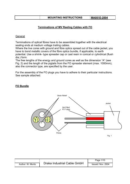
MOUNTING INSTRUCTIONS MA 001E-2004At a distance of around 15mm from the cable stripping edge, the FO bundle has tobe thickened up to ca. 12mm diameter by means of sticky tape (Photo 2). Treat thecorrugated tube in the same manner about 35mm from the said edge (Photo 3), with17mm target thickness (= Inner dia of entrance element).These thickened sections shall build a plug for the resin injected later on.Photo 2 Photo 3Slide the corrugated tube over the said structure in such a way that the thickenedpart of the bundle acts as a stopper within the corrugated tube (Photo 4). Finalposition of the plug around 5-8mm within the corrugated tube (fixed by means ofresin).Photo 4 Photo 5After that, the entry sleeve has to shifted over the thickened area, then fastened to itand sealed with sticky tape ( Photo 5).Page 4/10Author: W. Moritz <strong>Draka</strong> <strong>Industrial</strong> <strong>Cable</strong> <strong>GmbH</strong> Issued: Nov. 2004
MOUNTING INSTRUCTIONS MA 001E-2004Now you have to fasten the assembly in a vertical position and pour it with CellpackEG cast resin up to the brim of the entry sleeve (Photo 6).Photo 6 Photo 7When the resin is cured, incise and remove the FO tubes ca. 5mm from the resinsurface. The loose tube fibres are freely accessible now (Photo 7).Put each 1 spacer in the jointing sleeves (Photo 8).Photo 8Page 5/10Author: W. Moritz <strong>Draka</strong> <strong>Industrial</strong> <strong>Cable</strong> <strong>GmbH</strong> Issued: Nov. 2004
MOUNTING INSTRUCTIONS MA 001E-2004Slide the joint sleeve over the entry element such that the fibres become accessible.After cleaning the optical fibres with alcohol, insert them in the pigtails of the exitelement until they protrude out from the tubes (Photos 9, 10, 11).Photo 9 Photo 10Photo 11Page 6/10Author: W. Moritz <strong>Draka</strong> <strong>Industrial</strong> <strong>Cable</strong> <strong>GmbH</strong> Issued: Nov. 2004
MOUNTING INSTRUCTIONS MA 001E-2004Close the gap between joint sleeve and exit element by pulling carefully at the fibreends.Now the entrance element has to be connected to the exit element by means ofquick-drying adhesive (Photo 12).The finished system is then covered with a shrink tube (Photo 13).Photo 12 Photo 13Assembly of the connectors to be carried out acc. to instructions (see annex: Huber &Suhner variant) of the supplier. The ST- connector is shown here.Slide the boots and crimp ferrules over the loose tube fibres (Photo 14). Add also theidentification ferrules to the fibres at this stage.Photo 14Page 7/10Author: W. Moritz <strong>Draka</strong> <strong>Industrial</strong> <strong>Cable</strong> <strong>GmbH</strong> Issued: Nov. 2004
MOUNTING INSTRUCTIONS MA 001E-2004Insert the uncoated fibres into a plug connector filled with epoxy glue, then put themin the heating box (Photos 15, 16, 17).Photo 15 Photo 16Photo 17 Photo 18Page 8/10Author: W. Moritz <strong>Draka</strong> <strong>Industrial</strong> <strong>Cable</strong> <strong>GmbH</strong> Issued: Nov. 2004
MOUNTING INSTRUCTIONS MA 001E-2004After 30 minutes of curing, crimp the Kevlar strain relief of the loose tube fibres to theconnectors (Photo 18).Now you can treat the contact surface.Score the protruding fibre with a diamond tool and break it off. Then start the firstmanual polishing on 12µm fine grained emery (Photo 19).Photo 19 Photo 20The second polish has to be made on the machine (Photo 20).This can be done alternatively by means of a suitable manual lapping tool.An optical examination with a hand microscope is absolutely necessary (Photo 21).Photo 21Page 9/10Author: W. Moritz <strong>Draka</strong> <strong>Industrial</strong> <strong>Cable</strong> <strong>GmbH</strong> Issued: Nov. 2004
MOUNTING INSTRUCTIONS MA 001E-2004Upon completion of works, you have to measure and record the attenuation figures atall the treated fibres (Photo 22).Photo 22Page 10/10Author: W. Moritz <strong>Draka</strong> <strong>Industrial</strong> <strong>Cable</strong> <strong>GmbH</strong> Issued: Nov. 2004
SUHNERFST-Z/M-A001Assembly instructionsRequired components:<strong>Cable</strong> type :single fibre cable up to3.5 mm diameterboot crimp ferrule 1) connector protective capFibre type : E 10 / 125 µm1. Tools / assembly aidsFor the assembly of connectors, severaltools and assembly aids are required. Theseare contained in the tool kit 9801.90.P andthe set 9801.92.K.2. <strong>Cable</strong> preparationMeasure cable and cut it off with the sidecutter [calculate with a loss of length of15mm per connector]. Slide rubber boot andcrimp ferrule 1) , reduced end ahead, onto thecable.3. Connector preparationInsert glue syringe into connector until stop.Fill in 0.5 - 1 units of Epotek 360.Attach connector to assembly device.4. Stripping the cableStrip cable according to figure.The coating must be removed after thecleaning under point 5.5. Cleaning / assemblingRemove possible jelly thoroughly from thecoating with isopropyl alcohol or spirit.Following, remove the coating andclean with a dry tissue.Insert fibre and tube into connector withslight rotating motion until stop.6. Crimping 1) / curingNote: Before the crimping, the aramide yarnmust be spread evenly around the crimpneck. Slide on crimp ferrule and crimp withthe crimp tool ∅ 4.95mm once each on theback and front.With a slight rotating motion, slide rubberboot onto crimp ferrule.8. Pre-polishingPolish off the protruding fibre by hand incircles with a 30µm paper until the fibre is notprotuding any more and no glue rests arevisible [if necessary peel off with knife].Clean the connector ferrule well withisopropyl alcohol or spirit.9. Polishing the fibrePolish the fibre according to connectorspecification.Important: Never use the same cleaningtissue for different polishing procedures!10. Finish the assemblyClean connector well, put microscope[100-way] on the lapping tool. Control: Repeat lastpolishing process if heavy scratches appearin the light conducting core.Fibre end surfaces:Sequence of stripping:[Measures are only valid if tube is pushedback]L1 = 45 mm large cable stripperL4 = 7 mm aramide scissorsL3 = 15 mm small cable stripperL2 = 17 mm coating removerFor 0.9mm tube assembling only:L6 = 0 mm small cable stripperL5= 28 mm coating remover[The indicated measures have a tolerance of±1 mm]Cure connector for 1 hour in the 120°C heatingbox .7. Score / break fibreRemove connector from the assemblydevice. Carefully, score the fibre with scoringtool and, applying tension, break it; disposeof waste.Clean connector again completely, and at theend put on the protective cap.1) Only required for strain relieved cables!Issued: Checked: Released: last amendment: Modification code: Document No.:02.02.95 / 332 09.02.95 / 603 09.02.95 / 218 18.01.01 / 704 c 52.23.0004.4