3.091 â Introduction to Solid State Chemistry Lecture Notes No. 6 ...
3.091 â Introduction to Solid State Chemistry Lecture Notes No. 6 ...
3.091 â Introduction to Solid State Chemistry Lecture Notes No. 6 ...
- No tags were found...

You also want an ePaper? Increase the reach of your titles
YUMPU automatically turns print PDFs into web optimized ePapers that Google loves.
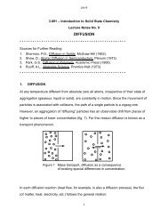
LN–6<strong>3.091</strong> – <strong>Introduction</strong> <strong>to</strong> <strong>Solid</strong> <strong>State</strong> <strong>Chemistry</strong><strong>Lecture</strong> <strong><strong>No</strong>tes</strong> <strong>No</strong>. 6THE IMPERFECT SOLID STATE1. INTRODUCTIONReal crystals are never perfect: they always contain a considerable density of defectsand imperfections that affect their physical, chemical, mechanical and electronicproperties. The existence of defects also plays an important role in varioustechnological processes and phenomena such as annealing, precipitation, diffusion,sintering, oxidation and others. It should be noted that defects do not necessarily haveadverse effects on the properties of materials. There are many situations in which ajudicious control of the types and amounts of imperfections can bring about specificcharacteristics desired in a system. This can be achieved by proper processingtechniques. In fact, “defect engineering” is emerging as an important activity.All defects and imperfections can be conveniently considered under four main divisions:point defects, line defects or dislocations, planar defects or interfacial or grain boundarydefects, and volume defects. We can also add here macroscopic or bulk defects suchas pores, cracks and foreign inclusions that are introduced during production andprocessing of the solid state. Point defects are inherent <strong>to</strong> the equilibrium state andthus determined by temperature, pressure and composition of a given system. Thepresence and concentration of other defects, however, depend on the way the solidwas originally formed and subsequently processed.Briefly consider the effects of imperfections or crystal defects on a few importantproperties of solids. The electrical behavior of semiconduc<strong>to</strong>rs, for example, is largelycontrolled by crystal imperfections. The conductivity of silicon can thus be altered intype (n or p) and by over eight orders of magnitude through the addition of minute1
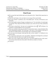
LN–6The presence of surface defects such as cracks causes brittle materials like glass <strong>to</strong>break at small applied stresses. This fact is familiar <strong>to</strong> anyone who has broken a glasstube by first filing a small notch (or crack) in<strong>to</strong> the surface. Removal of cracks from thesurface of glass either by etching in hydrofluoric acid or by flame polishing almostalways raises the fracture strength. For example, glass in the absence of any surfacecracks has a fracture strength of ~10 10 New<strong>to</strong>n/m 2 (as opposed <strong>to</strong> real glass which hasa fracture strength of ~10 7 New<strong>to</strong>n/m 2 ).2. POINT DEFECTSA. Formation of Point DefectsAn incontrovertible law of nature states: “<strong>No</strong>thing is perfect”. This law applies <strong>to</strong>humans as well as <strong>to</strong> the inorganic world of crystalline solids and can be formulated asthe 2nd law of thermodynamics:F = H – TS (1)where F is the free energy of a given system, H is the heat content or enthalpy and TSis the entropy, or disorder, term. If a reaction takes place at a temperature T, we find thechange in F (ΔF) related <strong>to</strong> a change in H (ΔH), the heat content, and possibly also achange in TS (TΔS). Such is the case when defects are formed in a perfect solid: Theenergy distribution in a solid (Maxwell-Boltzmann) suggests that a number of individuala<strong>to</strong>ms may acquire enough thermal energy <strong>to</strong> be displaced from the equilibrium latticesite in<strong>to</strong> an interstitial position. This process of point defect formation requires energyand leads <strong>to</strong> lattice strain which constitutes, as discussed earlier, an increase in theheat content of the system (ΔH is positive and increases linearly with the number ofdefects formed). The departure from perfection by the generation of defects leads <strong>to</strong>disorder (ΔS is positive). The magnitude of disorder generated (ΔS) is very large duringthe initial step from perfection <strong>to</strong> slight disarray, but the increase in disorder (with agiven number of defects generated) decreases as the overall disorder increases.3
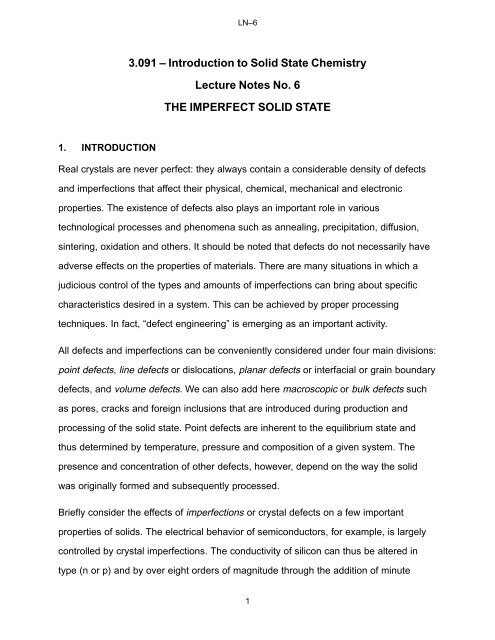
+Δ energyLN–6Correspondingly the term TΔS drops rapidly at the beginning and then flattens out. Thenet result (fig. 1), free energy, exhibits a minimum for a certain number of defects in thesolid [equilibrium defect0-Hn equil.F-TSn (defect density)density = f (temperature)]; theF minimum suggests also thatthe transition from perfection<strong>to</strong> equilibrium defect structureis spontaneous: it occursnaturally!Figure 1 Thermodynamics of point defectformationWhile the detailedmechanisms for the formationof a<strong>to</strong>mic vacancies in solids are still the subject of extensive research, the associatedequilibrium energetics are clear: calculations of the thermal energy of a<strong>to</strong>ms in a latticeshow that the average vibrational energy of lattice a<strong>to</strong>ms is much less than 1 eV (theapproximate energy change associated with vacancy formation, i.e., the least amoun<strong>to</strong>f energy required <strong>to</strong> form a vacancy) at room temperature. Therefore a lattice a<strong>to</strong>mwill only acquire the energy ΔH d , the energy required <strong>to</strong> form the defect, upon theoccurrence of a large energy fluctuation. Since the relative probability of an a<strong>to</strong>mhaving an energy ΔH d or more in excess of the ground state energy is e *DH d kT , theprobability that an a<strong>to</strong>mic site is vacant varies in the same way. In a (molar) crystalcontaining N a<strong>to</strong>mic sites, the number n d of vacant sites is, therefore,n d+ ANe *DH d kT (2)where: n d = the number of defects (in equilibrium at T)N = the <strong>to</strong>tal number of a<strong>to</strong>mic sites per moleΔH d = the energy necessary <strong>to</strong> form the defectT = the absolute temperature (K)4
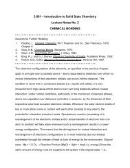
LN–6k = the Boltzmann constant A = proportionality constant B. Point Defects in “Pure” Metallic SystemsPoint defects in “pure” crystalline metals are defects of a<strong>to</strong>mic dimensions, such asimpurity a<strong>to</strong>ms, the absence of a matrix a<strong>to</strong>m and/or the presence of a matrix a<strong>to</strong>m inthe wrong place. Some of these point defects are shown in fig. 2. An impurity a<strong>to</strong>m thatsubstitutionaloccupies a normal latticesite is called ainterstitialsubstitutional impuritya<strong>to</strong>m and an impuritya<strong>to</strong>m found in thevacancyselfinterstitialinterstice between matrixa<strong>to</strong>ms is called aninterstitial impurity a<strong>to</strong>m.Whether a foreign a<strong>to</strong>mFigure 2 Point defects in crystalline solidswill occupy a substitutionalor interstitial site depends largely on the size of the a<strong>to</strong>m relative <strong>to</strong> the size of the site.Small a<strong>to</strong>ms are usually interstitial impurities, while larger a<strong>to</strong>ms are usuallysubstitutional impurities.A vacancy is an a<strong>to</strong>m site, normally occupied in the perfect crystal, from which an a<strong>to</strong>mis missing. Often the term “vacancy” is used <strong>to</strong> denote a so-called Schottky defect,which is formed when an a<strong>to</strong>m or an ion leaves a normal lattice site and repositionsitself in a lattice site on the surface of the crystal. This may be the result of a<strong>to</strong>micrearrangement in an existing crystal at a high temperature when a<strong>to</strong>mic mobility is highbecause of increased thermal vibrations. A vacancy may also originate in the process5
LN–6of crystallization as a result of local disturbances during the growth of new a<strong>to</strong>micplanes on the crystal surface. Vacancies are point defects of a size nearly equal <strong>to</strong> thesize of the original (occupied) site; the energy of the formation of a vacancy is relativelylow - usually less than 1 eV.The number of vacancies at equilibrium at each temperature in a crystal can bedetermined from eq. (2), in which ΔH d is the energy necessary <strong>to</strong> take an a<strong>to</strong>m from aregular site of the crystal and place it on the surface for a Schottky-type defect. When asolid is heated a new higher equilibrium concentration of vacancies is established,usually first at crystal surfaces and then in the vicinity of dislocations and grainboundaries which provide sites for the a<strong>to</strong>ms which have left their normal lattice site.Vacancies gradually spread throughout the crystal (from the surfaces in<strong>to</strong> the bulk). Oncooling the vacancy concentration is lowered by “diffusion of vacancies” <strong>to</strong> grainboundaries or dislocations, which act as sinks. In both cases, the new equilibriumvacancy concentration is established only after a finite amount of time. The rate atwhich vacancies move from point <strong>to</strong> point in the lattice decreases exponentially withdecreasing temperature. Thus, on very rapid cooling (quenching) from a hightemperature near the melting point most of the vacancies do not have time <strong>to</strong> diffuse <strong>to</strong>sinks and are said <strong>to</strong> be “frozen in”. This gives a considerably greater(“non-equilibrium”) concentration of vacancies in quenched specimens than thatindicated by the thermal equilibrium value.The concentration of vacant lattice sites in pure materials is very small at lowtemperatures - about one vacancy every 10 8 a<strong>to</strong>m sites - and increases with increasingtemperature <strong>to</strong> about one vacancy every 10 3 sites at the melting temperature.Vacancies are important because they control the rate of matrix (or substitutional) a<strong>to</strong>mdiffusion - i.e., a<strong>to</strong>ms are able <strong>to</strong> move around in a crystalline solid primarily because ofthe presence of vacancies. (The mechanism by which they move is the same as that6
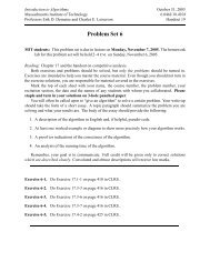
LN–6associated with moving a car in a filled parking lot <strong>to</strong> the exit). This is shownschematically in fig. 3. Self-interstitials are generally not encountered in close-packed1 2 3 48 7 6 5Figure 3 Dynamics of vacancy movements in a close packed solidmetallic systems, but may be introduced by irradiation. For example, high-energyneutrons from a<strong>to</strong>mic fission can knock metal a<strong>to</strong>ms from their regular sites in<strong>to</strong>interstitial sites, creating vacancy-interstitial pairs.C. Point Defects in Ionic <strong>Solid</strong>sPoint defects in ionic structures differ from those found in pure elements because of thecharge neutrality requirement. For example, in a pure monovalent ionic material acation vacancy must have associated with it either a cation interstitial or an anionvacancy <strong>to</strong> maintain charge neutrality. Similar requirements hold for anion vacancies. Avacancy pair defect (migration of a cation and an anion <strong>to</strong> the surface) is usually calleda Schottky imperfection, and a vacancy-interstitial pair defect is referred <strong>to</strong> as a Frenkelimperfection (an anion or cation has left its lattice position, which becomes a vacancy,and has moved <strong>to</strong> an interstitial position). These two types of imperfections are shownin fig. 4. Self-interstitials are much more common in ionic structures than in pureelements because many ionic compounds have relatively large interstitial sitesavailable. That is, there are often interstitial sites in the unit cell that have nearly the7
LN–6+ -Schottky defect+ - + - + - + -- + - + - - +same surroundings asnormal a<strong>to</strong>m sites.(For example, in BeOthe Be a<strong>to</strong>ms fill onlyone-half the available+-+-+-++--+-+-++-+-+-+-tetrahedral sites,leaving four possiblecation interstitial sitesper unit cell. Thus aBe a<strong>to</strong>m could go-+ - +Frenkel defect-+-+from a regular latticesite <strong>to</strong> an almostequivalent interstitialFigure 4 Point defects in ionic solids.site with littledis<strong>to</strong>rtion of thelattice.)Foreign a<strong>to</strong>ms in ionic crystals produce defects that also must maintain chargeneutrality. For example, in NaCl a monovalent cation, such as lithium, may simplyreplace one of the sodium ions as a substitutional impurity. But a divalent cation, suchas calcium, replacing a sodium ion must be accompanied by either a cation vacancy oran anion interstitial if charge neutrality is <strong>to</strong> be maintained. Correspondingly,monovalent impurity cations in a divalent structure (e.g., Na in MgO) must beaccompanied by an appropriate number of cation interstitials or anion vacancies.D. Point Defects in Covalently Bonded <strong>Solid</strong>sSubstitutional impurities in covalently bonded materials can create a uniqueimperfection in the electronic structure if the impurity a<strong>to</strong>m is from a group in theperiodic table other than the matrix a<strong>to</strong>ms. For example, you already considered GroupV and Group III elements in a Group IV matrix, such as As or B in Si.8
LN–6When foreign a<strong>to</strong>ms are incorporated in<strong>to</strong> a crystal structure, whether in substitutionalor interstitial sites, we say that the resulting phase is a solid solution of the matrixmaterial (solvent) and the foreign a<strong>to</strong>ms (solute). The term “solid solution”, however, isnot restricted <strong>to</strong> the low solute contents of doped semiconduc<strong>to</strong>r systems; there aremany solid solutions, such as metallic alloys, that comprise a wide composition range.3. LINE DEFECTSLine imperfections, or dislocations, in crystalline solids are defects that produce latticedis<strong>to</strong>rtions centered about a line. A dislocation is simply the edge of an extra insertedfractional plane of a<strong>to</strong>ms (fig. 5). <strong>No</strong>rmally the symbol is used <strong>to</strong> represent a positiveFigure 5 Schematic presentation of a dislocation; the last rowof a<strong>to</strong>ms (dark) in the inserted fractional planedislocation (extra fractional plane) and is used <strong>to</strong> represent a negative dislocation(missing fractional plane).The importance of dislocations is readily demonstrated in the deformation of crystallinematerials. The plane in which a dislocation moves through the lattice is called a slipplane. With an applied shear stress the dislocation moves, a<strong>to</strong>mic row by a<strong>to</strong>mic row,and one part of the crystal is displaced relative <strong>to</strong> the other. When the dislocation haspassed through the crystal, the portion of the crystal above the slip plane has shifted9
LN–6one a<strong>to</strong>mic distance relative <strong>to</strong> the portion below the slip plane. In other words, themotion of the dislocation has caused the crystal <strong>to</strong> change its shape - <strong>to</strong> bepermanently deformed (fig. 6).1 2 3 4xxxxxxxxxxxxxxxx5 6 7x x x x x xx xx xx xslip planeFigure 6 Plastic deformation of crystalline solid by slip associated with stress inducedmotion of dislocationPlease note: on either side of the dislocation the crystal lattice is essentially perfect, butin the immediate vicinity of the dislocation the lattice is severely dis<strong>to</strong>rted. For a positiveedge dislocation, the presence of the extra half plane causes the a<strong>to</strong>ms above the slipplane <strong>to</strong> be put in compression, while those below the slip plane are put in tension.Consequently, the edge dislocation will have a stress field around it that is compressiveabove the slip plane and tensile below the slip plane.Plastic Deformation By Slip:When single crystals of metal (or semiconduc<strong>to</strong>r) are pulled in tension, they will begin <strong>to</strong>deform (elongate) plastically at relatively low stress levels, and “blocks” of the crystalsslide over one another because of dislocation motion. Simultaneously, so-called slip10
LN–6lines appear on their surface. It is found that deformation by slip occurs most easily onplanes with high a<strong>to</strong>mic density and with large interplanar spacing, while the direction ofslip is in all instances an a<strong>to</strong>mically “close-packed direction”. For FCC structures wetherefore observe as the primary slip system {111} planes in direction, while inBCC structures the primary slip occurs on {110} planes in directions. (It shouldbe noted that an alternate deformation mechanism is “deformation twinning”, presentlynot <strong>to</strong> be considered.)Dislocation Climb:Climb is the name given <strong>to</strong> the motion of dislocations when the extra “half” plane isextended farther in<strong>to</strong> a crystal or partially withdrawn from it. Clearly, the climb processis not a motion of the plane, but rather its growth or shrinking as a result of the additionof a<strong>to</strong>ms or “vacancies” respectively from the environment of the dislocation (fig. 7).Figure 7 Dislocation climb by (a) loss of a<strong>to</strong>ms <strong>to</strong> surrounding vacanciesand (b) incorporation of interstitial a<strong>to</strong>ms.Multiplication of Dislocations:Since during slip each dislocation leaves the matrix, macroscopic deformation could nottake place given normal dislocation densities in the range of 10 6 -10 8 /cm 3 . Examinationof the deformed crystals indicates that multiplication of dislocations takes place during11
LN–6deformation. While there are a multitude of multiplication mechanisms, the one mostextensively studied is the Frank-Read Source (not <strong>to</strong> be discussed in detail).Dislocation Interactions:The relative ease with which dislocations move across a solid matrix can be attributed<strong>to</strong> the severe displacements of a<strong>to</strong>ms in the core of dislocations. If these local stressesare reduced, the mobility of dislocations - and thus the ease of slip - is reduced. It isfound that impurities in the vicinity of dislocation cores tend <strong>to</strong> reduce the localdis<strong>to</strong>rtion energy of the dislocations and thus stabilize the system against slip. In manysystems impurities are intentionally added (e.g., solid solution hardening) <strong>to</strong> increasethe strength of materials. Similarly, micro-precipitates tend <strong>to</strong> impede dislocation motion(e.g., precipitation hardening).4. INTERFACIAL IMPERFECTIONSThe several different types of interfacial, or planar imperfections, in solids can begrouped in<strong>to</strong> the following categories:1. Interfaces between solids and gases, which are called free surfaces;2. Interfaces between regions where there is a change in the electronicstructure, but no change in the periodicity of a<strong>to</strong>m arrangement, known asdomain boundaries;3. Interfaces between two crystals or grains of the same phase where there isan orientation difference in the a<strong>to</strong>m arrangement across the interface;these interfaces are called grain boundaries;4. Interfaces between different phases, called phase boundaries, where thereis generally a change of chemical composition and a<strong>to</strong>m arrangementacross the interface.Grain boundaries are peculiar <strong>to</strong> crystalline solids, while free surfaces, domainboundaries and phase boundaries are found in both crystalline and amorphous solids.12
LN–6A. Free SurfacesBecause of their finite size, all solid materials have free surfaces. The arrangement ofa<strong>to</strong>ms at a free surface differs slightly from the interior structure because the surfacea<strong>to</strong>ms do not have neighboring a<strong>to</strong>ms on one side. Usually the a<strong>to</strong>ms near the surfacehave the same crystal structure but a slightly larger lattice parameter than the interiora<strong>to</strong>ms.Perhaps the most important aspect of free surfaces is the surface energy (γ) associatedwith surfaces of any solid. The source of this surface energy may be seen byconsidering the surroundings of a<strong>to</strong>ms on the surface and in the interior of a solid. Tobring an a<strong>to</strong>m from the interior <strong>to</strong> the surface, we must either break or dis<strong>to</strong>rt somebonds - thereby increasing the energy. The surface energy is defined as the increase inenergy per unit area of new surface formed. In crystalline solids, the surface energydepends on the crystallographic orientation of the surface - those surfaces that areplanes of densest a<strong>to</strong>mic packing are also the planes of lowest surface energy. This isbecause a<strong>to</strong>ms on these surfaces have fewer of their bonds broken or, equivalently,have a larger number of nearest neighbors within the plane of the surface. Typicalvalues of surface energies of solids range from about 10 –1 <strong>to</strong> 1 J/m 2 . Generally, thestronger the bonding in the crystal, the higher the surface energy.Surface energies can be reduced by the adsorption of foreign a<strong>to</strong>ms or molecules fromthe surrounding atmosphere. For example, in mica the surface energy of freshlycleaved material in a vacuum is much higher than the surface energy of the samesurface cleaved in air. In this instance, oxygen is adsorbed from the air <strong>to</strong> partiallysatisfy the broken bonds at the surface. Impurity a<strong>to</strong>m adsorption makes it almostimpossible <strong>to</strong> maintain a<strong>to</strong>mically clean surfaces. As a result, surface properties suchas electron emission, rates of evaporation and rates of chemical reactions areextremely dependent on the presence of any adsorbed impurities. These properties will13
LN–6be different if the measurements are made under conditions giving different surfaceadsorption.B. Grain BoundariesGrain boundaries separate regions of different crystallographic orientation. Thesimplest form of a grain boundary is an interface composed of a parallel array of edgedislocations. This particular type of boundary is called a tilt boundary because themisorientation is in the form of a simple tilt about an axis, parallel <strong>to</strong> the dislocations. Tiltboundaries are referred <strong>to</strong> as low-angle boundaries because the angle of misorientationis generally less than 10°.When a grain boundary has a misorientation greater than 10° or 15°, it is no longerpractical <strong>to</strong> think of the boundary as being made up of dislocations because the spacingof the dislocations would be so small that they would lose their individual identity. Thegrain boundary represents a region a few a<strong>to</strong>mic diameters wide where there is atransition in a<strong>to</strong>mic periodicity between adjacent crystals or grains.Grain boundaries have an interfacial energy because of the disruption in a<strong>to</strong>micperiodicity in the vicinity of the boundary and the broken bonds that exist across theinterface. The interfacial energy of grain boundaries is generally less than that of a freesurface because the a<strong>to</strong>ms in a grain boundary are surrounded on all sides by othera<strong>to</strong>ms and have only a few broken or dis<strong>to</strong>rted bonds.<strong>Solid</strong>s with grain boundaries are referred <strong>to</strong> as polycrystalline, since the structure iscomposed of many crystals - each with a different crystallographic orientation. In thecase of iron the grain boundary structure can be revealed by preferential chemicalattack (etching) at the grain boundaries, while the grain structure in polyethylene isrevealed by the use of polarized light. The grain structure is usually specified by givingaverage grain diameter or by using a scheme developed by the American Society forTesting and Materials (ASTM). In the ASTM procedure the grain size is specified by a14
LN–6“grain size number” (n) whereN = 2 n–1with N equal <strong>to</strong> the number of grains per square inch when the sample is viewed at100X magnification. For example, at a magnification of X = 100, a material with grainsize number 8 will show 128 grains per inch 2 - this material in effect has (at X = 1)1.28 x 10 6 grains per square inch. If the grains are approximately square in crosssection, this corresponds <strong>to</strong> an average grain dimension of 8.8 x 10 –4 in*.In polycrystalline samples the individual grains usually have a random crystallographicorientation with respect <strong>to</strong> one another, and the grain structure is referred <strong>to</strong> asrandomly oriented. In some instances, however, the grains all have the sameorientation <strong>to</strong> within a few degrees. In this instance the material is said <strong>to</strong> have apreferred orientation or texture.C. Phase BoundariesA phase is defined as a homogeneous, physically distinct and mechanically separableportion of the material with a given chemical composition and structure. Phases may besubstitutional or interstitial solid solutions, ordered alloys or compounds, amorphoussubstances or even pure elements; a crystalline phase in the solid state may be eitherpolycrystalline or exist as a single crystal.<strong>Solid</strong>s composed of more than one element may - and often do - consist of a number ofphases. For example, a dentist’s drill, something painfully familiar <strong>to</strong> all of us, consistsof a mixture of small single crystals of tungsten carbide surrounded by a matrix ofcobalt. Here the cobalt forms a continuous phase. Polyphase materials such as thedentist’s drill are generally referred <strong>to</strong> as composite materials. Composite materialshave great importance in the engineering world because they have many attractiveproperties that set them apart from single-phase materials. For example, the dentist’s*ASTM has as yet not issued specifications in SI units!15
LN–6drill has good abrasive characteristics (due <strong>to</strong> the hard carbide particles) and good<strong>to</strong>ughness and impact resistance (due <strong>to</strong> the continuous cobalt matrix). Neither thetungsten carbide nor the cobalt has both abrasion resistance and impact resistance, yetthe proper combination of the two phases yields a composite structure with the desiredproperties.The nature of the interface separating various phases is very much like a grainboundary. Boundaries between two phases of different chemical composition anddifferent crystal structure are similar <strong>to</strong> grain boundaries, while boundaries betweendifferent phases with similar crystal structures and crystallographic orientations may beanalogous <strong>to</strong> low-angle grain boundaries in both energy and structure.The concept of a solid consisting of a continuous phase and a discontinuous phase (orphases) leads <strong>to</strong> a simple classification of the various types of composite materials.Table 1 gives this classification, which is based on the structure (whether amorphous orcrystalline) of the continuous and discontinuous phases.16
LN–6TABLE 1Classification of Composite or Multiphase Materials____________________________________________________________________________Discontinuous PhaseContinuous Phase (or Phases) Examples____________________________________________________________________________Crystalline Crystalline All metallic systems such as castiron, steel, soft solder, etc.; mostnatural rocks such as granite andmarble.Crystalline Amorphous <strong>No</strong>ne of practical significance.Amorphous Crystalline Most man-made ceramics suchas building bricks and electricalinsula<strong>to</strong>r porcelain, concrete,partially crystalline polymers,some polymer-crystalline particlecomposites.Amorphous Amorphous Fiberglass, asphalt, wood,hydrated cement, other gels.____________________________________________________________________________17
LN–6EXERCISE FOR THE IDLE MIND1. The energy required for vacancy formation (ΔH V ) in Ni is listed as 1.12 eV. For Niat 2°C below the melting point temperature, determine the number of occupiedlattice sites for every vacancy, assuming equilibrium.2. The energy for vacancy formation (ΔH V ) is 1.08 eV in Cr. How many occupiedlattice sites are encountered at 1°C below the melting point of Cr for everyvacancy generated?3. Given the equilibrium vacancy concentration for Al at 300°C as 2 x 10 17 /cm 3 ,determine for this metal the energy of vacancy formations (ΔH V ) in eV/vacancy.4. Experimental studies have established that the ratio of the vacancy densities(n V /cm 3 ) in Mo at 500°C and 900°C is 2 x 10 –3 . What is the energy for vacancyformation (ΔH V ) in this system?5. In a crystal at 800°C, one out of every 10 10 lattice sites is found <strong>to</strong> be a vacancy.What is the energy of vacancy formation (ΔH V ) in this material if at 900°C one ou<strong>to</strong>f every 3 x 10 9 sites is found <strong>to</strong> be vacant?6. In iron (Fe) the energy associated with the generation of a vacancy is 1.05 eV. Atwhat temperature (T) in °C will one out of 10 5 lattice sites be vacant?7. A “cubic” metal (r = 0.77 Å) exhibits plastic deformation by slip along directions. Determine its planar packing density (a<strong>to</strong>ms/m 2 ) for its densest familyof planes.8. Determine the (approximate) grain diameter (in µm) for a polycrystalline materialwith the ASTM grain size number 7 (seven). (See LN6).9. (a) List four (4) different defects in crystalline solids.(b) What evidence is available supporting the actual existence of the listeddefects?10. If the ratio of the vacancy densities (n d /cm 3 ) at 500°C and 800°C is found <strong>to</strong> be10 –3 , what is the energy for vacancy formation (E d ) in eV/vac?11. The energy of formation of a vacancy in copper (E d ) is 1.2 eV. Estimate thepercent volume change that takes place when the crystal is heated <strong>to</strong> its meltingtemperature. (Consider only the expansion due <strong>to</strong> the “absorption” of vacancies.)18
LN–612. Silicon <strong>to</strong> be used for device fabrication contains 10 21 aluminum a<strong>to</strong>ms per m 3 .What is the weight percent (wt%) of Al present in this silicon?13. Attempt <strong>to</strong> account for the fact that polycrystalline Al has a higher tensile strengththan single crystalline Al. Support your answer with an appropriate sketch.14. In BCC metals the fraction of vacant lattice sites is usually about 1 in 2000 justbelow their melting points. What is the molar energy of vacancy formation in solidtungsten (W) at its melting point?15. (a) Name four types of crystal defects present in close packed metallic systemsas obtained, for example, by casting.(b) Which of these defects can be avoided if the solid phase is a “perfect” singlecrystal?(c) Which defect is primarily responsible for the fact that metals do not exhibittheir theoretical tensile strength?(d) Which defect accounts for the phenomenon of solid state diffusion in theseclose packed systems?16. From theoretical considerations it is concluded that the (activation) energyrequired <strong>to</strong> form an interstitial a<strong>to</strong>m in copper (Cu) is about 4 eV. Assuming thisvalue <strong>to</strong> be correct, determine the equilibrium concentration of these defects(defects/cm 3 ) at 1350K.17. (a) The activation energy <strong>to</strong> form a Schottky defect in copper is 0.89 eV.Calculate the change in density (σ) due <strong>to</strong> Schottky defect formation uponheating copper from 300K <strong>to</strong> 1200K.(b) Experimentally the change in density is found <strong>to</strong> be –6.45%. Attempt <strong>to</strong>account for any differences between the experimentally determined and thetheoretically predicted values.18. The work required <strong>to</strong> form one mole of vacancies in copper (Cu) wasexperimentally determined <strong>to</strong> be 20,000 cal. Based on this data, determine theconcentration of vacancies (vacancies/cm 3 ) at 1350K.19. Determine the ASTM grain size number (n) for polycrystalline material whichexhibits grains with an average diameter of 100 x 10 –6 m. (Give n as the integerwhich approximates best the given grain size.)20. On appropriate schematic drawings show the generation and characteristics ofSchottky defects in (1) a closed-packed metal, (2) an ionic crystal and (3) asemiconduc<strong>to</strong>r.19
LN–621. In a given material it is found that one out of 10 11 a<strong>to</strong>mic sites is vacant at 750°Cand one out of 10 10 sites is vacant at 850°C. At what temperature will one out of10 8 a<strong>to</strong>mic sites be vacant?22. The energy of vacancy formation (ΔH V ) in Al (aluminum) is 1.05 eV. Given thisinformation, determine the vacancy density (n V /cm 3 ) at 50°C below the meltingpoint of Al.23. What is the maximum radius an element may have if it is <strong>to</strong> be accommodatedinterstitially in “solid” crystalline oxygen (assume hard sphere behavior).24. Identify three types of crystal defects in solids and suggest for each of these onematerials property which is adversely affected by its presence and one which isimproved.25. Define the following by an appropriate equation or in no more than two sentences:(a) deBroglie wavelength(b) Bohr postulate(c) Schottky defect(d) Heisenberg uncertainty principle(e) Schrödinger wave equation(f) Moseley relationship(g) Bragg’s law20
![18.03 Class 21, April 3 Fun with Fourier series [1] If f(t) is any decent ...](https://img.yumpu.com/51148985/1/190x245/1803-class-21-april-3-fun-with-fourier-series-1-if-ft-is-any-decent-.jpg?quality=85)