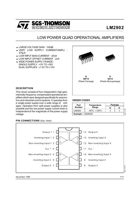
LM2902
LM2902
LM2902
- No tags were found...

Create successful ePaper yourself
Turn your PDF publications into a flip-book with our unique Google optimized e-Paper software.
<strong>LM2902</strong>ELECTRICAL CHARACTERISTICS (continued)Symbol Parameter Min. Typ. Max. UnitV OH High Level Output Voltage(VCC = +30V)VTamb = +25 o CRL=2kΩ27V OLTmin. ≤ Tamb ≤ Tmax.T amb = +25 o CT min . ≤ T amb ≤ T max .(V CC = +5V, R L =2kΩ)T amb = +25 o CT min . ≤ T amb ≤ T max .R L = 10kΩLow Level Output Voltage (R L = 10kΩ)T amb = +25 o CTmin. ≤ Tamb ≤ Tmax.SR Slew Rate (VCC = 15V, VI = 0.5 to 3V,R L =2kΩ,C L = 100pF, T amb = +25 o C,unity gain) 0.4GBPTHDenGain Bandwidth Product (VCC = 30Vf = 100kHz, Tamb = +25 o C, Vin = 10mVR L =2kΩ,C L = 100pF) 1.3Total Harmonic Distortion(f = 1kHz, AV = 20dB, RL =2kΩ,VO=2VppCL = 100pF, Tamb = +25 o C, VCC = 30V) 0.015Equivalent Input Noise Voltage(f = 1kHz, Rs = 100Ω, VCC = 30V) 40262627273.53285 2020DVio Input Offset Voltage Drift 7 30 µV/ o CDI IO Input Offset Current Drift 10 200 pA/ o CV O 1/V O 2 Channel Separation (note 5)1kHz ≤ f ≤ 20kHz 120dBNotes :1. Short-circuits from the output to V CC can cause excessive heating if V CC > 15V. The maximum output currentis approximately 40mA independent of the magnitude of V CC. Destructive di ssipation can result from simultaneousshort-circuit on all amplifiers.2. The direction of the input current is out of the IC. This current is essentially constant, independent of the stateof the output so no loading change exists on the input lines.3. V o = 1.4V, R s =0Ω, 5V < V CC + < 30V, 0 < V ic
<strong>LM2902</strong>2902-07.EPS2902-08.EPS2902-05.EPS2902-06.EPS2902-03.EPS2902-04.EPS5/11
<strong>LM2902</strong>2902-09.EPS6/11
<strong>LM2902</strong>2902-12.EPS2902-13.EPS2902-10.EPS2902-11.EPSTYPICAL SINGLE - SUPPLY APPLICATIONSAC COUPLED INVERTING AMPLIFIERAC COUPLED NON-INVERTING AMPLIFIERC IR110kΩe I ~ R2V CC 100kΩR100kΩf1/4<strong>LM2902</strong>R6.2kΩ BR3100kΩA =- R fV R1(as shown A V = -10)C oe o0 2V PPR10kΩ LR1 R2100kΩ 1MΩA V=1+ R2R1(as shown A V = 11)C o1/40 2V PPC <strong>LM2902</strong>I e oR BR6.2kΩ 10kΩ LeR3I ~ 1MΩV CCC10.1µFR4100kΩC110µFC210µFR5100kΩ2902-14.EPS2902-15.EPS7/11
<strong>LM2902</strong>TYPICAL SINGLE - SUPPLY APPLICATIONSNON-INVERTING DC GAINDC SUMMING AMPLIFIERe 1100kΩ10kΩ1/4<strong>LM2902</strong>e O +5VA V =1+ R2 R1(As shown = 101) A Ve 2100kΩ100kΩ1/4<strong>LM2902</strong>e OR110kΩR21MΩe O (V)e 3100kΩ0e I (mV)100kΩe 4100kΩ2902-16.EPSeo =e1+e2-e3-e4where (e1 +e2)≥ (e3 +e4)to keep eo ≥ 0V2902-17.EPSHIGH INPUT Z ADJUSTABLE GAIN DCINSTRUMENTATION AMPLIFIERLOW DRIFT PEAK DETECTORR1100kΩI B1/4<strong>LM2902</strong>e 1R2Gainadjust2kΩR5100kΩ1/4<strong>LM2902</strong>e 2R3100kΩR6100kΩ1/4<strong>LM2902</strong>R7100kΩR4100kΩe Oe IZ I1/4<strong>LM2902</strong>C1µ F 2I* B2I BR1MΩ* Polycarbonate or polyethylene1/4I B <strong>LM2902</strong>2N9290.001µFI B3R3MΩI BZ oe o1/4<strong>LM2902</strong>Input currentcompensationif R1 =R5and R3 =R4=R6=R7eo=[1+ 2R1R 2] (e2 − e1)As shown e o = 101 (e 2 -e 1 ).2902-18.EPS2902-19.EPS8/11
<strong>LM2902</strong>TYPICAL SINGLE - SUPPLY APPLICATIONSACTIVER BANDPASS FILTERHIGH INPUT Z, DC DIFFERENTIAL AMPLIFIERR1100kΩFor R 1= R 4R 2 R 3(CMRR depends on this resistor ratio match)C1330pFe 1R310kΩFO = 1kHz1/4<strong>LM2902</strong>R410MΩ1/4<strong>LM2902</strong>C2330pFR6470kΩR8100kΩ1/4<strong>LM2902</strong>C310µFR5470kΩR7100kΩe OV CCR1100kΩR2100kΩ1/4<strong>LM2902</strong>R3100kΩR4100kΩ+V1 <strong>LM2902</strong> Vo+V2eo (1+ R 4)(e2−e1)R3As shown eo =(e2 -e1)1/4Q=50AV= 100 (40dB)2902-20.EPS2902-21.EPSUSING SYMMETRICAL AMPLIFIERS TO REDUCE INPUT CURRENT (GENERAL CONCEPT)I II B1/4<strong>LM2902</strong>e oe II B2N9290.001µFI B1.5MΩI B3MΩI B1/4<strong>LM2902</strong>Aux. amplifier for inputcurrent compensation2902-22.EPS9/11
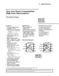
<strong>LM2902</strong>PACKAGE MECHANICAL DATA14 PINS - PLASTIC DIP OR CERDIPPM-DIP14.EPSDimensionsMillimetersInchesMin. Typ. Max. Min. Typ. Max.a1 0.51 0.020B 1.39 1.65 0.055 0.065b 0.5 0.020b1 0.25 0.010D 20 0.787E 8.5 0.335e 2.54 0.100e3 15.24 0.600F 7.1 0.280i 5.1 0.201L 3.3 0.130Z 1.27 2.54 0.050 0.100DIP14.TBL10/11
<strong>LM2902</strong>PACKAGE MECHANICAL DATA14 PINS - PLASTIC MICROPACKAGE (SO)PM-SO14.EPSDimensionsMillimetersInchesMin. Typ. Max. Min. Typ. Max.A 1.75 0.069a1 0.1 0.2 0.004 0.008a2 1.6 0.063b 0.35 0.46 0.014 0.018b1 0.19 0.25 0.007 0.010C 0.5 0.020c145 o (typ.)D 8.55 8.75 0.336 0.334E 5.8 6.2 0.228 0.244e 1.27 0.050e3 7.62 0.300F 3.8 4.0 0.150 0.157G 4.6 5.3 0.181 0.208L 0.5 1.27 0.020 0.050M 0.68 0.027S8 o (max.)SO14.TBLInformation furnished is believed to be accurate and reliable. However, SGS-THOMSON Microelectronics assumes no responsibilityfor the consequences of use of such information nor for any infringement of patents or other rights of third parties whichmay result from its use. No licence is granted by implication or otherwise under any patent or patent rights of SGS-THOMSONMicroelectronics. Specifications mentioned in this publication are subject to change without notice. This publ ication supersedesand replaces all information previously supplied. SGS-THOMSON Microelectronics products are not authorized for use as criticalcomponents in life support devices or systems without express written approval of SGS-THOMSON Microelectronics.© 1995 SGS-THOMSON Microelectronics - All Rights ReservedSGS-THOMSON Microelectronics GROUP OF COMPANIESAustralia - Brazil - France - Germany - Hong Kong - Italy - Japan - Korea - Malaysia - Malta - Morocco - The NetherlandsSingapore - Spain - Sweden - Switzerland - Taiwan - Thailand - United Kingdom - U.S.A.ORDER CODE :11/11