CPU-2000 10-09 - Altronic Inc.
CPU-2000 10-09 - Altronic Inc.
CPU-2000 10-09 - Altronic Inc.
- No tags were found...

You also want an ePaper? Increase the reach of your titles
YUMPU automatically turns print PDFs into web optimized ePapers that Google loves.
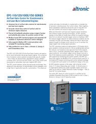
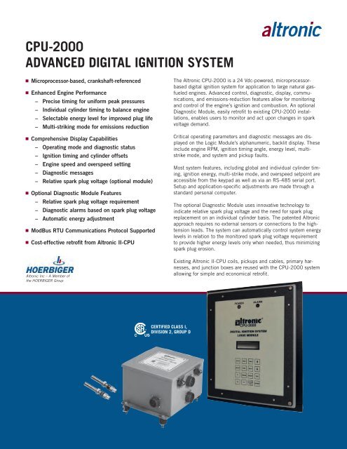
(EXISTING)SYSTEM<strong>CPU</strong> PICK-UPPICK-UP SIGNALSOPTIONALALTRONIC <strong>CPU</strong>-<strong>2000</strong>DIAGNOSTIC MODULE1R 2R 3RENGINE(1 TO 20 CYLINDERS)1L 2L 3LIGNITION COILS (EXISTING)IGNITIONOUTPUTSALTRONIC <strong>CPU</strong>-<strong>2000</strong>OUTPUT MODULEComprehensive Display CapabilityTwo-line display indicates the following operating parameters:n System status and moden Diagnostic messagesn Global timing (in degrees BTDC)n Individual cylinder timingn Value of timing control signal (4–20mA)n Engine speed (in RPM)n Engine overspeed setpointSpark Characteristic ControlFor improved engine performance and combustion stability, orignition of lean mixtures for emissions reduction:n Multi-striking mode (selectable ON/OFF)n Ignition energy level controln Second spark plug cut-off controln Automatic energy adjustment (optional)Ignition Timing Control ModesLocal and remote control of ignition timing allows engine startingand running perfor mance to be optimized.Typical Primary and Secondary Diagnostic Displaysn Keypad control (global or individual cylinders)n Serial data-link control (global or individual cylinders)n Analog 4-20mA control (global)n Timing control vs. RPMSerial CommunicationsAll system features, display data, and configuration inputs areaccessible by an integral RS-485 serial data-link. ModBus RTUcommunications are fully supported for integration into supervisorymonitoring and control systems.System ConfigurationEngine-specific configuration parameters, including those listedbelow, are contained in a plug-in memory which can be unpluggedand used in a spare unit if necessary. The memory canbe configured at the factory or in the field by an IBM compatiblecomputer connected to the serial data link.n Engine firing patternn Number of gear teeth or flywheel holes sensedn Timing control vs. 4-20mA or RPMDiagnostics, Testing, and ShutdownAdvanced diagnostic, self-test, and alarm/shutdown capabilitiesare included in each <strong>CPU</strong>-<strong>2000</strong> system.Automatic Energy Adjustment FeaturevThe optional Diagnostic Module provides an automatic energyadjustment feature based on the monitored spark plug voltage.This enables the system to operate at its low energy setting(E1) when conditions permit. When conditions call for a higherspark demand (threshold is user adjustable), the system willautomatically switch to the middle energy setting (E2); a higherthreshold can be set to effect a similar transition to the highestenergy (E3). In operation, the system selects the lowest energylevel to satisfy current conditions, thereby minimizing sparkplug erosion rates.n Status of system pickupsn Verification of number of teeth/holesn Cylinder-specific primary and secondary discharge faults(optional)n Test firing of selected cylinder(s)n Overspeed conditionn Alarm and shutdown outputsInstallation/Retrofit to <strong>Altronic</strong> II-<strong>CPU</strong>With many system components retained, conversion from anexisting <strong>Altronic</strong> II-<strong>CPU</strong> to the <strong>CPU</strong>-<strong>2000</strong> is simple and economical.
SpecificationsLogic Module DimensionsINPUTSMagnetic Pickups (2)1 – flywheel holes or ring gear teeth1 – reset (1/engine revolution)Hall-effect pickup for compression stroke reference(4-cycle applications only)Timing Control InputsAnalog:................................................4–20 mA control signalDigital:...................................................... RS-485 serial dataManual:................... Logic Module keypad, misc. input terminalRS-485 serial communications — ModBus RTU communicationsprotocol supportedOUTPUTS16 or 32 ignition outputsRS-485 serial communications — ModBus RTU communicationsprotocol supportedOutput characteristicsMaximum output voltage.................................................47kVSpark duration..................................... 300–700 microsecondsOutput Module DimensionsDISPLAYBacklit, alphanumeric 2 X 16 characterPOWER REQUIREMENTS24 Vdc, 1 to 4 Amps typical(Current consumption varies by application)TEMPERATURE–40° F. to +158° F.–40° C. to +70° C.Ordering Information<strong>CPU</strong>-<strong>2000</strong> Logic Module............................................... 291<strong>10</strong>0–1Diagnostic Module Dimensions<strong>CPU</strong>-<strong>2000</strong> Output Module16-output...............................................................291116–132-output — standard............................................. 291132–132-output — special............................................... 291132–2<strong>CPU</strong>-<strong>2000</strong> Diagnostic Module....................................... 291<strong>10</strong>5–1See <strong>CPU</strong>-<strong>2000</strong> application list for further details.<strong>Altronic</strong>, <strong>Inc</strong>.712 Trumbull Avenue / Girard, Ohio 44420(330) 545-9768 / Fax: (330) 545-9005www.altronicinc.com Email: sales@altronicinc.comForm <strong>CPU</strong>-<strong>2000</strong> <strong>10</strong>-<strong>09</strong> ©20<strong>09</strong> <strong>Altronic</strong>, <strong>Inc</strong>.