Pulse Suppressor Box FTB-PSB - Rohde & Schwarz
Pulse Suppressor Box FTB-PSB - Rohde & Schwarz
Pulse Suppressor Box FTB-PSB - Rohde & Schwarz
- No tags were found...

Create successful ePaper yourself
Turn your PDF publications into a flip-book with our unique Google optimized e-Paper software.
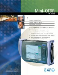
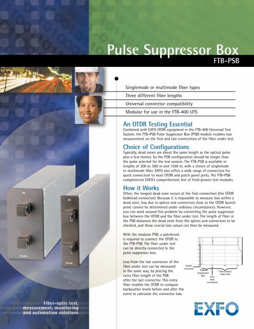
<strong>Pulse</strong> <strong>Suppressor</strong> <strong>Box</strong><strong>FTB</strong>-<strong>PSB</strong>Singlemode or multimode fiber typesThree different fiber lengthsUniversal connector compatibilityModular for use in the <strong>FTB</strong>-400 UTSAn OTDR Testing EssentialCombined with EXFO OTDR equipment in the <strong>FTB</strong>-400 Universal TestSystem, the <strong>FTB</strong>-<strong>PSB</strong> <strong>Pulse</strong> <strong>Suppressor</strong> <strong>Box</strong> (<strong>PSB</strong>) module enables lossmeasurement on the first and last connections of the fiber under test.Choice of ConfigurationsTypically, dead zones are about the same length as the optical pulseplus a few meters. So the <strong>PSB</strong> configuration should be longer thanthe pulse selected for the test session. The <strong>FTB</strong>-<strong>PSB</strong> is available inlengths of 300 m, 500 m and 1500 m, with a choice of singlemodeor multimode fiber. EXFO also offers a wide range of connectors forquick connection to most OTDR and patch panel ports. The <strong>FTB</strong>-<strong>PSB</strong>complements EXFO’s comprehensive line of field-proven test modules.How it WorksOften, the longest dead zone occurs at the first connection (the OTDRbulkhead connector). Because it is impossible to measure loss within adead zone, loss due to splices and connectors close to the OTDR launchpoint cannot be determined under ordinary circumstances. However,you can work around this problem by connecting the pulse suppressorbox between the OTDR and the fiber under test. The length of fiber inthe <strong>PSB</strong> distances the dead zone from the splices and connectors to bechecked, and these crucial loss values can then be measured.With the modular <strong>PSB</strong>, a patchcordis required to connect the OTDR tothe <strong>FTB</strong>-<strong>PSB</strong>. The fiber under testcan be directly connected to thepulse suppressor box.Loss from the last connector of thefiber under test can be measuredin the same way, by placing theextra fiber length of the <strong>PSB</strong>after the last connector. This extrafiber enables the OTDR to comparebackscatter levels before and after theevent to calculate the connector loss.OTDRconnector<strong>Pulse</strong><strong>Suppressor</strong><strong>Box</strong>FirstfiberconnectionFiber sectionunder test
<strong>Pulse</strong> <strong>Suppressor</strong> <strong>Box</strong>SpecificationsOrdering InformationDescriptionTypical specificationsFor singlemode fiber onlyConnector insertion loss (dB) < 0.5 (maximum initial)Connector reflectance (dB) UPC: < -50APC: < -60Fiber type Wavelength Typical attenuation rangeMultimode fiber 50/125 µm 850 nm 2.4 to 3.0 dB/km1300 nm 0.6 to 1.2 dB/kmMultimode fiber 62.5/125 µm 850 nm 3.0 to 3.2 dB/km1300 nm 0.7 to 0.9 dB/kmSinglemode fiber 9/125 µm 1310 nm ≤ 0.35 dB/km1550 nm ≤ 0.25 dB/kmRefers to fiber typeB = singlemode fiber 9/125 µmC = multimode fiber 50/125 µmD = multimode fiber 62.5/125 µm<strong>FTB</strong>-<strong>PSB</strong>-X-XXXX-XX-YYFiber length (m)300 1500 31500 31st and 2nd ConnectorsEIEAWhere EUI connectorsmust be selected89 = FC narrow key90 = ST 291 = SC95 = E-2000 3General SpecificationsSize (H × W × D)Single slotDouble slotWeightSingle slotDouble slot9.6 cm × 2.5 cm × 26 cm (3 3 /4 in × 1 in × 10 1 /4 in)9.6 cm × 5.1 cm × 26 cm (3 3 /4 in × 2 in × 10 1 /4 in)325 g (0.72 lb)495 g (1.09 lb)Notes1. Available for multimode fiber only.2. Available for EI only.3. Available for singlemode fiber only.Find out more about EXFO’s extensive line of high-performance portable instruments by visiting our Web site at www.exfo.comRugged Handheld Solutions• OLTS• Power Meter• Light Source• Talk SetUNIVERSAL TEST SYSTEM• OTDR• OLTS• ORL• SwitchOptical FiberDWDM Test Systems• OSA• PMD• Chromatic Dispersion Analyzer• Multiwavelength MeterProtocol• 10/100 and Gigabit Ethernet• SONET/SDH (DS0 to OC-192c)• SDH/PDH (64Kb/s to STM-64c)CORPORATE HEADQUARTERS 465 Godin Avenue Vanier (Quebec) G1M 3G7 CANADA Tel.: 1 418 683-0211 · Fax: 1 418 683-2170EXFO AMERICA 1201 Richardson Drive, Suite 260 Richardson TX 75080 USA Tel.: 1 800 663-3936 · Fax: 1 972 907-2297EXFO EUROPE Le Dynasteur, 10/12 rue Andras Beck 92366 Meudon la Forêt Cedex FRANCE Tel.: +33.1.40.83.85.85 · Fax: +33.1.40.83.04.42EXFO ASIA-PACIFIC 151 Chin Swee Road, #03-29 Manhattan House SINGAPORE 169876 Tel.: +65 333 8241 · Fax: +65 333 8242TOLL-FREE (USA and Canada) Tel.: 1 800 663-3936 www.exfo.com • info@exfo.comEXFO is certified ISO 9001 and attests to the quality of these products. This device complies with Part 15 of the FCC Rules. Operation is subjectto the following two conditions: (1) this device may not cause harmful interference, and (2) this device must accept any interference received,including interference that may cause undesired operation. EXFO has made every effort to ensure that the information contained in thisspecification sheet is accurate. However, we accept no responsibility for any errors or omissions, and we reserve the right to modify design,characteristics and products at any time without obligation. Units of measurement in this document conform to SI standards and practices.Contact EXFO for prices and availability or to obtain the phone number of your local EXFO distributor.For the most recent version of this spec sheet, please go to the EXFO Web site at http://www.exfo.com/support/techdocs.aspIn case of discrepancy, the Web version takes precedence over any printed literature.SP<strong>FTB</strong><strong>PSB</strong>.2AN © 2002 EXFO Electro-Optical Engineering Inc. All rights reserved. Printed in Canada 02/05 W