MG Terminal GSM modem USER MANUAL
MG Terminal GSM modem USER MANUAL
MG Terminal GSM modem USER MANUAL
- No tags were found...
You also want an ePaper? Increase the reach of your titles
YUMPU automatically turns print PDFs into web optimized ePapers that Google loves.
<strong>MG</strong> <strong>Terminal</strong><strong>GSM</strong> <strong>modem</strong><strong>USER</strong> <strong>MANUAL</strong>
<strong>MG</strong> <strong>Terminal</strong>User Manual1. Safety RequirementsRestrictions for the usage of the device in the vicinity of other electronic devices:· turn off the <strong>modem</strong> in hospitals or in the vicinity of medical equipment (e.g.cardiostimulators, hearing aids). It can cause interference for medical equipment;· turn off the <strong>modem</strong> in aircrafts. Take measures against accidental activation;· turn off the <strong>modem</strong> in the vicinity of gas-filling stations, chemical enterprises, blastingwork places. It can cause interference to technical devices;· at a short range the <strong>modem</strong> may cause harmful interference to TV and radio receivers.Prevent the <strong>modem</strong> from dust and moisture.Improper use deprives you of all warranty claims.3
4that is, explaining the differences through a history of gene duplications and losses—isknown as lineage sorting or reconciliation and produces a list of gene duplications andlosses along each edge in the species tree. While reconciliation is a hard computationalproblem, algorithms have been devised for it in a Bayesian framework [2] or using asimple parsimony criterion [10].3 THE NEW NETWORK EVOLUTION MODELAlthough transcriptional regulatory networks produced from bench experiments areavailable for only a few model organisms, other types of data have been used to assistin the comparative study of regulatory mechanisms across organisms [9, 24, 25].For example, gene-expression data [25], sequence data like transcriptional factor bindingsite (TFBS) data [9, 24], and cis-regulatory elements [25] have all been used inthis context. Moreover, a broad range of model organisms have been studied, includingbacteria [4], yeast [9, 25], and fruit fly [24], thus spanning a broad evolutionary range.However, while these studies are promising, they have not to date sufficed to establisha clear model for regulatory networks or their evolution.Our new model remains simple, but can easily be generalized or associated withother models, such as the evolutionary model of TFBSs [16]. In this new model, thenetworks are represented by binary adjacency matrices. The evolutionary operationsare:– Gene duplication: a gene is duplicated with probability p d . After a duplication,edges for the newly generated copy can be assigned as follows:Neutral initialization: Create connections between the new copy and other genesrandomly according to the proportion π 1 of edges in the background networkindependently of the original copy.Inheritance initialization: Connections of the duplicated copy are reported to correlatewith those of the original copy [4, 23, 26]. This observation suggests lettingthe new copy inherit the connections of the original, then lose some ofthem or gain new ones at some fixed rate [6].ΠPreferential attachment: The new copy gets preferentially connected to genes withhigh connectivity [5, 6].– Gene loss: a gene is deleted along with all its connections with probability p l .– Edge gain: an edge between two genes is generated with probability p 01 .– Edge loss: an existing edge is deleted with probability p 10 .The model parameters are thus p d , p l , the proportions of 0s and 1s in the networksPpπ 0 π 1¡, the substitution matrix of 0s and 1s, 00 p 01parametersp 10 p 11plussuitable to the initialization model.4 THE NEW REFINEMENT METHODSWe begin by collecting the regulatory networks to be refined. These networks may havealready been inferred or they can be inferred from gene-expression data at this pointusing any of the standard network inference methods introduced in Sec. 2.1. The genesin these networks are not required to be orthologous across all species, as the duplication/lossmodel allows for gene families of various sizes. Refinement proceeds in the
<strong>MG</strong> <strong>Terminal</strong>User ManualInterfaces:· connector for audio interface· connector RJ11 for audio interface connection,· connector DB9 for connection of the data cable RS-232,· connector FME for <strong>GSM</strong> antenna connection.5
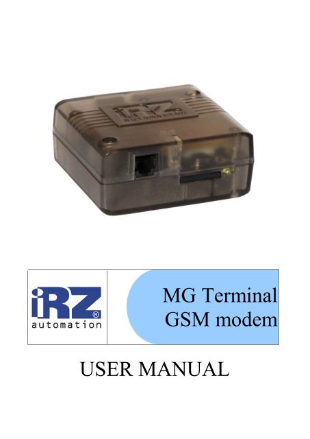
<strong>MG</strong> <strong>Terminal</strong>User Manual2.3. Exterior AppearanceThe <strong>modem</strong> <strong>MG</strong> <strong>Terminal</strong> is a compact device completed in a plastic housing. The externalappearance is represented on Fig.2.4.1 and Fig.2.4.2.1 23 4Fig.2.4.1 Front view.657Fig.2.4.2 Back view.On the figures the digits signify the following:1. connector for audio interface connection,2. network LED indicator,3. SIM card tray,4. SIM card tray extracting button,5. connector DB9 for connection of the data cable RS232,6. connector for power supply connection7. connector FME for <strong>GSM</strong> antenna connection.6
<strong>MG</strong> <strong>Terminal</strong>User Manual2.4. Interfaces2.4.1. Connector DB9 (RS232)The connector is used for connection to the control device, exchange protocol RS232.543 219876Fig.2.5.1 Connector DB9Table 2.5.1 Purpose of the connector pins.Pin Signal Direction Purpose1 DCD Modem-PC Availability of carrier wave2 RXD Modem-PC Data reception3 TXD PC-Modem Data transmission4 DTR PC-Modem Availability of data receiver5 GND general System housing6 DSR Modem-PC Readiness of data7 RTS PC-Modem Request for transmission8 CTS Modem-PC Availability of transmission9 RI Modem-PC Call signal7
<strong>MG</strong> <strong>Terminal</strong>User Manual2.4.2. Power supply connector RJ11The connector is used for connection of electric power supply.1 6Fig.2.5.2 Connector RJ11Table 2.5.2 Purpose of power supply connector pinsContact Signal Purpose1 + 12V Positive pole of DC supply voltage. Protected with a fuse and theprotection circuit against voltage-surge (with voltage infeed ratemore than 30V) and incorrect polarity.2 not used3 not used4 not used5 not used6 GND System housing8
<strong>MG</strong> <strong>Terminal</strong>User Manual2.4.3. Audio Interface Connector RJ111 4Fig.2.5.3 Connector RJ11Table 2.5.2 Purpose of the power supply connector pins.Contact Signal Purpose1 not used2 MICP microphone input and microfone power supply not inverse3 SPKP phone output not inverse4 SPKN phone output inverse5 MICN phone input inverse6 not used9
<strong>MG</strong> <strong>Terminal</strong>User Manual2.5. Modem Status IndicationLED indication is provided in the <strong>modem</strong> for connection status indication.Table 2.6.1 Connection status indicationIndication modeOperation modeTurned offModem is turned off or there is an emergency situation600 ms on / 600 ms Modem is not registered in the networkoff75 ms on / 3 s off Modem is registered in the network75 ms on / 75 ms off / GPRS connection is installed75 ms on / 3 s off500 ms on / 50 ms off Data transmission is underway10
<strong>MG</strong> <strong>Terminal</strong>User Manual3. Connection and Setting Up3.1. ConnectionBefore feeding the power supply you need to install the SIM card in the <strong>modem</strong> (the SIM cardmust be enabled). To do this, you need:· to extract the SIM tray by pressing the SIM tray extract button (Fig. 2.4.1);· to install the SIM card into the SIM tray;· to insert the SIM tray with the SIM card into the <strong>modem</strong>.No strong physical efforts must be applied while installing the SIM card.Connect the <strong>GSM</strong> antenna to the antenna connector, as well as the commutating cable (RS232).Feed power supply to the <strong>modem</strong> through the connector RJ11 (Fig. 2.4.2).Note: <strong>GSM</strong> antenna, data cables and electrical power unit are not included in the complete setconfiguration.After the power supply feeding, registration occurs automatically, which is signaled by the greenindicator frequent flashing. After the registration is completed, the <strong>modem</strong> jumps to the operatingmode, the green indicator flashes less frequently (Table 2.6.1).3.2. Control, Restarting and Power OffThe <strong>modem</strong> control is performed by standard AT commands. For additional information andsupport visit the manufacturer’s site – www.radiofid.ru.Modem restarting can be carried out by the following ways:· by the program method through AT commands,· by eight jumpings of the DTR COM port line into passive state (DTR < 3V), duration ofpulses and the pauses between the pulses must lie within the range 100-500 ms,· by temporary power-off.The <strong>modem</strong> can be powered off using the following ways:· by the program method, using AT commands (escape to the power standby mode);· directly by power-off.After power-off made by means of AT commands, the <strong>modem</strong> escapes to the power standbymode (minimum power consumption). Escaping from the power standby mode is performed uponthe DTR of the COM port.11


