Dynamic characterization of a 3-D full scale steel-concrete ...
Dynamic characterization of a 3-D full scale steel-concrete ...
Dynamic characterization of a 3-D full scale steel-concrete ...
- No tags were found...

You also want an ePaper? Increase the reach of your titles
YUMPU automatically turns print PDFs into web optimized ePapers that Google loves.
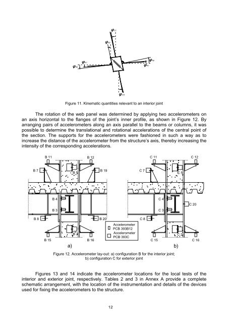
c,tspspb,lb,rspc,bFigure 11. Kinematic quantities relevant to an interior jointThe rotation <strong>of</strong> the web panel was determined by applying two accelerometers onan axis horizontal to the flanges <strong>of</strong> the joint’s inner pr<strong>of</strong>ile, as shown in Figure 12. Byarranging pairs <strong>of</strong> accelerometers along an axis parallel to the beams or columns, it waspossible to determine the translational and rotational accelerations <strong>of</strong> the central point <strong>of</strong>the section. The supports for the accelerometers were fashioned in such a way as toincrease the distance <strong>of</strong> the accelerometer from the structure’s axis, thereby increasing theintensity <strong>of</strong> the corresponding accelerations.B 11B 12C 11C 12B 7B 5B 19C 7C 5B 4B 3C 4C 3C 20B 8B 20C 8B 15B 2B 16AccelerometerPCB 393B12AccelerometerPCB 393CC 15a) b)C 2C 16Figure 12. Accelerometer lay-out: a) configuration B for the interior joint;b) configuration C for exterior jointFigures 13 and 14 indicate the accelerometer locations for the local tests <strong>of</strong> theinterior and exterior joint, respectively. Tables 2 and 3 in Annex A provide a completeschematic arrangement, with the location <strong>of</strong> the instrumentation and details <strong>of</strong> the devicesused for fixing the accelerometers to the structure.12