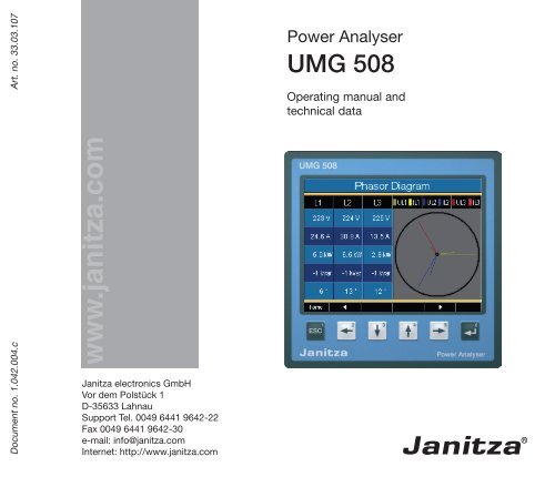
www .janitza.com
www .janitza.com
www .janitza.com
- No tags were found...
Create successful ePaper yourself
Turn your PDF publications into a flip-book with our unique Google optimized e-Paper software.
UMG 508General 3Goods-in Check 6Description 8Intended Use 8Features 9Measurement Method 10GridVis network analysis software 11Assembly 12Place of Installation 12Installation extradata 12Front Board Cutout 12Ethernet Connection 13Fixing 13Installation 14Supply Voltage 14Voltage Measurement 16Current measurement 22RS485 26Ethernet 30Digital outputs 32Digital Inputs 34Operation 36Measurement value displays 37"Home“ measurement value display 38Select measurement value display 39Call up additional information 40Delete min/max values individually 41List of transients 42List of events 43Configuration 44Language 45Communication 46Measurement 48Transients 54Events 56Display 58System settings 60Password 61Delete minimum and maximum values 62Delete power meters 63Extensions 66Initialization 70Applying the supply voltage 70Apply measurement voltage 71Rotary field direction 71Applying measurement current 72Checking the power measurement 74Checking <strong>com</strong>munication 75Profibus 76Service and Maintenance 80Technical data 84Dimensioned drawings 94Configuration overview 96Measurement value displays overview 98Connection example 1002
UMG 508Meaning of SymbolsThe following pictograms are used in this handbook:cmGefährliche Spannung!Danger of death or risk of major injury.Disconnect the system and device beforebeginning any work.Caution!Please pay attention to the documentation.This symbol should warn againstpossible dangers that can occur duringassembly, initialization and use.Protective ground connection.Inductive.The voltage lags the currentCapacitive.The voltage lags the current.C Note.4
UMG 508Application InformationPlease read this operating manual and all otherpublications that have to be consulted to workwith this product (particularly for installation,operation or maintenance).Please pay attention to all safety regulations andwarning information. If you fail to follow the information,it can result in personal damage and/or damages to the product.Specialists are persons who, due to their relevanttraining and experience, are capable of recognizingrisks and avoiding possible hazardsthat can be caused when operating or servicingthe device.When using the device, the necessary legal andsafety regulations should be considered additionallyfor the respective application case.Any unauthorized change or use of this devicebeyond the specified mechanical, electrical orother operating limits can cause personal damageand/or damage to the product.Any such unauthorized change represents "misuse"and/or "negligence" in the sense of guaranteefor the product and therefore makes theguarantee covering possible consequential damagesvoid.This device is to be exclusively operated andmaintained by a specialist.cmmCaution!If the device is not operated accordingto the operating manual, protection isno longer ensured and the device maycause dangers.Cables with single wires must be providedwith ferrules.Only screw plugs with the same polenumber and the same type of constructioncan be plugged together.5
UMG 508Goods-in CheckCorrect and safe operation of this device issubject to appropriate transportation, correctwarehousing, installation and assembly as wellas careful operation and maintenance. If it canbe assumed that safe operation without anydanger is no longer possible, the device mustbe taken out of operation immediately and securedagainst unintentional initialization.Unpacking and packing must take place, withthe usual care without applying force and usingsuitable tools. The devices must be checked forperfect condition with visual tests.It should be assumed that risk-free operation isnot possible if, for example:• There is visible damage,• it no longer works due despite the main supplybeing intact,• has been subject to unfavorable conditions(e.g. storage outside of the authorized climatelimits without adaptation to the room climate,thawing etc.) over a longer period of time ortransport stresses (e.g. a fall from a height, includingwithout any visisble external damageetc).• Please check the delivered items for <strong>com</strong>pletenessbefore starting with the installation ofthe device.CCCAll screw clamps that belong to thescope of supply are attached to thedevice.The installation and initialization instructionsalso describe options that donot belong to the scope of supply.All supplied options and design versionsare described on the delivery note.6
UMG 508Scope of SupplyQuantity Art.no. Description1 52 21 xxx 1) UMG5081 33 03 121 operating manual.1 51 00 116 CD with the following contents::- "GridVis“ programming software,- DEscription of functions, GridVis, UMG508,- UMG508, GSD file "U5080C2C.GSD“ for Profibus DP V0.1 10 01 601 screw clamp, pluggable, 2-pole (auxiliary power).1 10 01 653 screw clamp, pluggable, 5-pole (voltage measurement 1-4).1 10 01 674 screw clamp, pluggable, 8-pole (current measurement 1-4).1 10 01 952 screw clamp, pluggable, 6-pole (digital outputs).2 10 01 769 screw clamp, pluggable, 5-pole (digital inputs).1 08 01 504 3m patch cable, blue. (Connection UMG - switch/hub)1 08 01 505 2m patch cable, twisted (connection UMG - PC)1 52 19 301 fixing clips.1)Refer to delivery note for article number.Available accessoriesArt.no.Description13 10 539 Profibus plug, 9-pole DSUB, with integrated switchable terminatingresistors.29 01 903 seal, 144x144.7
UMG 508Features• Front board installation, 144x144mm,• Working temperature range -10°C .. +55°C,• Colour graphic display 320x240, 256 colours, 6 keys,• 8 digital inputs, 5 digital outputs,• 16Bit A/transformer, data memory 256MByte Flash, SDRAM 32Mbyte,• Continuous scanning of voltage and current measurement inputs with 20kHz,• Frequency range of fundamental oscillation 40Hz .. 70Hz• 4 voltage measurement inputs, 4 current measurement inputs,• Measurement in TN and TT networks,• RS485: Profibus DP/V0, Modbus RTU, Modbus-Master, BACnet (Option)• Ethernet: Web-Server, EMAIL, BACnet (Option),TCP/IP, EMAIL (SMTP), DHCP-Client (BootP),Modbus/TCP, Modbus RTU over Ethernet, FTP, ICMP (Ping), NTP, TFTP. BACnet (Option), SNMP.• Detection of transients >50µs and storage with up to 16000 scanning points,• Detection of more than 800 measurement values,• Measurement of harmonics 1 to 40, for- Uln, I, P (ref/supply) and- Q (ind/cap),• Programming own applications in Jasic.9
UMG 508Measurement MethodThe UMG508 measures without any gaps andcalculates all effective values over a 200ms Interval.The UMG508 measures the real effective value(TRMS) of the voltages and currents applied tothe measurement inputs.Operating ConceptYou can program the UMG508 in several waysand call up measurement values.• Direct- on the device using 6 keys and thedisplay.• Using the programming softwareGridVis.• Using the UMG508 homepagefor deviceswith an Ethernet interface.• Using the RS485 with theModbus-protocol.You can change and call up data with the helpof the Modbus address list (stored on the encloseddata carrier).Only operating the UMG508 using the integrateddisplay and the 6 keys is described in thisoperating manual.The GridVis programming software and thehomepage have their own "online assistance“.10
UMG 508GridVis network analysis softwareThe UMG508 can be programmed and readoutwith the GridVis network analysis softwareincluded in the scope of supply. A PC mustbe connected using a serial interface (RS485/Ethernet) to the UMG508.PCInterfaceConverterRS232RS485UMG508GridVis features• Programming the UMG508.• Configuration of recordings.• Recordings read-out.• Saving data in a database.• Graphic presentation of measurement values.• Programming specific applications for the client.Illu. Connection of a UMG508 to a PC using aninterface converter.PCEthernetUMG508Illu. Connection of a UMG508 to a PC usingEthernet.11
UMG 508AssemblyPlace of InstallationThe UMG508 is suitable for installation in fixed,weather protected switch boards. Conductingswitch boards have to be grounded.Installation extradataIn order to achieve sufficient ventilation, theUMG508 has to be installed vertically. The clearancehas to be at least 50mm at the top andbottom and 20mm at the side.Front Board CutoutCutout size: 138 +0.8 x 138 +0.8 mmWallEthernetConnectionAirflowAirflowIllu. UMG508 installation extradata; view fromback.m12Failure to maintain the minimum clearancescan destroy the UMG508 athigh environmental temperatures!
Ethernet ConnectionThe UMG508's Ethernet connection is locatedon the underside of the housing.Depending on the bending radius of the Ethernetcable and plug type, you must provide aconnection area beneath the UMG508.The connection area beneath the UMG508should not be less than 50 mm.50 mmEthernet ConnectionPatch CableUMG 508FixingThe UMG508 is fixed into the switch board withtwo fixing clips that are each mounted on thedevice at the top and bottom.Fixing Clips13
UMG 508InstallationProtective Wire ConnectionUse a ring cable lug for connecting the protectivewire to the UMG508.Supply VoltageA supply voltage is required to operate theUMG508. The type and level of the necessarysupply voltage is noted on the label.Before applying the supply voltage, make surethat the voltage and the frequency match thedetails on the label!The connection cables for the supply voltagemust be connected using a fuse. Use a UL/IEClisted fuse (6A type C).SeparatorFuseConnection point forprotective wireProtective wirecWarning14- danger of death!It is necessary for the protective wireconnection on the device to be connectedwith the system grounding.L1 L2 L3 N PEIllu. Connection example; connection of supplyvoltage to a UMG508.
cWarning!The inputs for the supply voltage aredangerous to touch!UMG 508cWarning!Please pay attention to the details onthe supply voltage provided on theUMG508 label.m- An isolator or circuit breaker must beprovided for the voltage supply in buildinginstallation.- The isolator must be attached nearto the device and must be easy for theuser to access.- The switch must be marked as a separatorfor this device.-Voltages above the authorized voltagerange can destroy the device.15
UMG 508Voltage MeasurementThree-phase 4 conductor systemsThe UMG508 can be used in three-phase 4 conductorsystems (TN, TT network) with a groundedneutral wire. The bodies of the electricalsystem are grounded.L1L2L3NPE347V/600V 50/60HzThree-phase 3 conductor systemsThe UMG508 is only suitable for use in IT networkswith restrictions, because the measurementvoltage is measured against the housingpotential and the input impedance of the devicecauses a leakage current against ground. Theleakage current can cause isolation monitoringin IT networks to respond.Connection variations with a voltage transformerare suitable for IT networks without any restrictions.L1L2L3Impedance600V 50/60HzV4V1V2V3VrefV4V1V2V3VrefAC/DCAC/DCSystemgrounding4M4M4M4M4MVoltage measurementUMG508DCAuxiliarypowerSystemgrounding4M4M4M4M4MDCVoltage measurementAuxiliary powerUMG508Illu. Basic circuit diagram, UMG508 in theTNnetwork.Illu. Basic circuit diagram, UMG508 in the IT networkwithout N.16
UMG 508Nominal VoltagesLists of the networks and their nominal networkvoltages in which the UMG508 can be used.Three-phase 4 conductor systems withgrounded neutral wire.U L-N / U L-L66V / 115V120V / 208V127V / 220V220V / 380V230V / 400V240V / 415V260V / 440V277V / 480V347V / 600V400V / 690V417V / 720VMaximum nominal voltage ofthe network according to ULMaximum nominal voltageof the networkIllu. Table of suitable network nominal voltagesfor the voltage measurement inputs accordingto EN60664-1:2003.Ungrounded three-phase 3 conductorsystems.U L-L66V115V120V127V200V220V230V240V260V277V347V380V400V415V440V480V500V577V600VMaximum nominal voltage ofthe networkIllu. Table of suitable network nominal voltagesfor the voltage measurement inputs accordingto EN60664-1:2003.17
UMG 508Voltage Measurement InputsThe UMG508 has 4 voltage measurement inputs(V1, V2, V3, V4).L1 L2L3N PEOvervoltageThe voltage measurement inputs are suitable formeasurements in networks in which overvoltagesin the overvoltage category 600V CATIII canoccur.FrequencyThe UMG508 requires the rated frequency formeasuring and calculating measurement values.The UMG508 is suitable for measurements innetworks with a rated frequency in the range of40Hz to 70Hz.10A(UL/IEC listed)C18A connection diagram does not haveto be configured for the measurementinputs V4 and I4.Illu. Connection example for voltage measurement.
UMG 508The following has to be considered when connectingthe voltage measurement:• A suitable separator is to be provided in orderto disconnect the UMG508 from the currentand voltage.cWarning!Voltages that exceed the authorizednetwork nominal voltages must beconnected using a voltage converter.• The separator must be placed near to theUMG508, labelled for the user and must beeasy to reach.• Use UL/IEC authorized overcurrent protectionand isolators (10A type C) only.• The overcurrent protection device must havea nominal value calculated for the short-circuitcurrent at the connection point.• Measurement voltages and measurementcurrents must <strong>com</strong>e from the same network.cccWarning!The UMG508 is not suitable for measuringDC voltages.Warning!The voltage measurement inputs on theUMG508 are dangerous to touch!Warning!The voltage measurement inputs maynot be used for voltage measurementin SELV circuits (Safety Extra Low Voltage).19
UMG 508Connection diagrams, voltage measurement20
UMG 508Connection diagrams, current measurement21
UMG 508Current measurementThe UMG508 is designed for connecting currentconverters with secondary currents of ../1A and../5A. Only alternating currents, and no directcurrents, can be measured.Each current measurement input can be loadedwith 120A for 1 second.L1 L2 L3N PES1S2S1S2S1S2cmc22Warning!The current measurement inputs aredangerous to touch.Warning!The UMG508 is not suitable for themeasurement of direct voltages.Grounding current converters!If a connection is provided for groundingthe secondary winding, this must beconnected with ground.Illu. Connection example, current measurementusing current converter.CA connection diagram does not haveto be configured for meaurement inputsV4 and I4.
UMG 508Current DirectionThe current direction can corrected on the deviceor individually using the available serial interfacesfor each phase.In the case of incorrect connection, subsequentreconnection of the current converter is not necessary.cCurrent converter connections!The secondary connections of the currentconverter must be short-circuitedto these before the electricity cablesare disconnected from the UMG508!If a test switch is available which automaticallyshorts the secondary currentconverter lines, it is sufficient to setthem to the "test" extradata, as long asthe short-circuiters have been checkedbeforehand.cOpen current converters!Extreme contact danger due to voltagepeaks can occur on current convertersthat are operated open on the secondaryside!For "anti-open current converters", thewinding isolation is calculated so thatthe current converters can be operatedopen. However, these current convertersare also dangerous to touch if theyare operated open.23
UMG 508Total current measurementIf the current is measured using two currentconverters, the total transfer ratio of the currentconverters must be programmed in theUMG508.ExampleThe current measurement takes place usingtwo current converters. Both current convertershave a transfer ratio of 1000/5A. The totalmeasurement is carried out with a 5+5/5A totalcurrent converter.The UMG508 must then be set as follows:Primary current: 1000A + 1000A = 2000ASecondary current:5AIllu. Example, current measurement using a totalcurrent converter.24
UMG 508Direct measurementNominal currents up to 5A can also be directlymeasured with the UMG508.Under consideration that the direct measurementwill be carried out for the current only inthree phase 4 wire systems with mains voltagetill• 127V/220V (300V CAT III) according UL• 277V/480V (300V CAT III)Ampere meterIf you do not want to measure the current withthe UMG508 alone, but also with an additionalampere meter, the ampere meter must be switchedin series to the UMG508.and three phase 3 wire systems with mainsvoltage till• 277V (300V CAT III) according UL• 480V (300V CAT III)Due to the fact that the UMG508 does nothave integrated protection for the currentmeasurement, this protection must be foreseenin the installation.Illu. Example, current measurement with an additionalampere meter.Illu. Example, direct current measurement.25
UMG 508RS485The RS485 interface is designed as a 9-poleDSUB socket on the UMG508.On this interface, the UMG508 supports the followingselection of protocols:• Modbus RTU• Profibus DP V0 SlaveFor connection, we re<strong>com</strong>mend a 9-pole Profibusplug, e.g. from the <strong>com</strong>pany Phoenix,type "SUBCON-Plus-ProfiB/AX/SC“ with articlenumber 2744380. (Janitza art.no: 13.10.539)DSUB socketfor Modbusor Profibus.Illu. UMG508 with DSUB socket for the RS485interface.26
UMG 508Connection of Bus LinesThe in<strong>com</strong>ing bus line is connected to clamps1A and 1B. The bus line for the next device inthe line is connected to clamps 2A and 2B. Ifthere is no further device in the line, the bus linehas to be terminated with resistors (switch toON).In switch extradata ON, clamps 2A and 2B areswitched off for the continuing bus line.Profibus connector (external)Terminating resistorsD-sub,9 pin,socketD-sub,9 pin,connectorOtherprofibusstationsScrew-type terminalsIllu. Profibus plug with terminating resistors.27
UMG 508ShieldsA twisted, shielded cable is foreseen for connectionsusing the RS485 interface.• Ground the shields of all cables leading to thecabinet at the cabinet entry point.• Connect the shield extensively and withgood conductivity with a low external voltageground.• Intercept the cable mechanically abovethe ground clip in order to avoid damagescaused by cable movements.• Use suitable cable insert guides, such as PGglands, to guide the cable into the switch cabinet.Cable typeThe cables used must be suitable for an environmentaltemperature of at least 80°C.Re<strong>com</strong>mended cable types:Unitronic Li2YCY(TP) 2x2x0.22 (Lapp cable)Unitronic BUS L2/FIP 1x2x0.64 (Lapp cable)Maximum cable length1200m at a Baud rate of 38.4k.CableStrain reliefCable shielding braid.Grounding clipLow external voltageground.Illu. Shielding arrangement at cabinet entrypoint.Terminal resistorsThe cable is terminated with resistors (120Ohm1/4W) at the beginning and end of a segment.The UMG508 does not have any terminal resistors.28
UMG 508EthernetThe network settings for the Ethernet are specifiedby the network administrator and set accordinglyon the UMG508.If the network settings are not known, the patchcable may not be plugged into the UMG508.Ethernet connectionPatch cablemWarning!Incorrect nework settings can causefaults in the network!30
UMG 508PCUMG508DHCPServerPCUMG508Patch cablePatch cable(twisted)Illu. Connection example; direct connectionbetween the UMG508 and PC using a twistedpatch cable (art. no. 08.01.505)SwitchIllu. Connection example; UMG508 and PC areautomatically allocated the IP address from aDHCP server.PCUMG508Patch cableSwitchIllu. Connection example; UMG508 and PCneed a fixed IP address.31
UMG 508Digital outputsThe UMG508 has 5 digital outputs. These outputsare separated galvanically from the analysiselectronics using optocouplers. The digitaloutputs have a <strong>com</strong>mon reference.• The digital outputs can switch AC and DCloads.• The digital outputs arenotshort-circuit proof.• Connected lines that are longer than 30mmust be laid with shields.• External auxiliary power is necessary.~Illu. Digital outputs connection.32
UMG 508UMG508Digital outputs 1-5Digital Outputs 1-5Externalauxiliary power24VAC~~DigitalOutput 5DigitalOutput 4111213K1 K2DigitalOutput 314DigitalOutput 215DigitalOutput 1Illu. Connection of two relays to digital outputs4 and 5.1633
UMG 508Digital InputsThe UMG508 has 8 digital inputs. The digital inputsare divided into two groups, each with 4inputs. Each group has a <strong>com</strong>mon reference.- +UMG508Digital Inputs 1-4Digital Inputs 1-43.9V4k4k3.9V10DigitalInput 19DigitalInput 2Externalauxiliary powerS1S224VDC+ -- +4k4k3,9V3,9V8DigitalInput 37DigitalInput 46Illu. Example for the connection of digital inputs.Illu. Example for the connection of external contactsS1 and S2 to the digital inputs 1 and 2.34
UMG 508S0 impulse inputYou can connect an S0 impulse generator in accordancewith DIN EN62053-31 to each digitalinput.You require an external auxiliary voltage with anoutput voltage in the range of 20 .. 28V DC anda resistor with 1.5kOhm.UMG508Digitale Inputs 1-4Digital Inputs 1-44k 3.9V10DigitalInput 14k4k3.9V3.9V9DigitalInput 28DigitalInput 3Externalauxiliary voltage24VDC+ -S0Impulsegenerator1.5k4k3.9V7DigitalInput 46Illu. Example for the connection of an S0 impulsegenerator to digital input 1.35
UMG 508OperationThe UMG508 is operated using six functionkeys.The six keys are allocated different functionsdepending on the context:• Selection of measurement value displays.• Navigation within the menu.• Processing the device settings.Display titlesMeasurement valuesFunction key labelingFunction keys36
UMG 508Measurement value displaysMain valuesYou can use keys 2 and 5 to browse betweenthe main values of the measurement value displays.DisplayPointer diagramDisplayConfigurationDisplay"Home“DisplayVoltages L-NMain valuesAuxiliary valuesYou can use keys 3 and 4 to browse betweenthe auxiliary values of a measurement value display.DisplayVoltage L-NAuxiliary valuesDisplayVoltages L-L37
UMG 508"Home“ measurement value displayOnce the network returns, the UMG508 startswith the "Home“ measurement value display.This measurement value display contains thedevice names and an overview of importantmeasurement values. The device name consistsof the device type and serial number upon delivery.Using the "Home - Key 1“, you <strong>com</strong>eout of the measurement value displaysfor the main values directly tothe first "Home" measurement valuedisplay.38
UMG 508Select measurement value displayYou want to change to a measurement valuedisplay with main values.• Use the function keys 2 and 5 to browse betweenthe measurement value displays of themain values.• With function key 1 (Home), you always accessthe first measurement value display.You want to change to a measurement valuedisplay with auxiliary values.• Select the measurement value display withthe main values.• Select the measurement value display withfunction keys 3 and 4 for the auxiliary values.DisplayVoltage L-NDisplayVoltages L-LExample: selection of auxiliary value voltage.39
UMG 508Call up additional information• Browse with keys 2 to 5 to the required measurementvalue display.• Activate the measurement value selectionwith key 6 (selection).• Select the required measurement value withkeys 2 to 5.• The background colour for the measurementvalue changes from grey to green. The additionalinformation is shown in a blue window.• End the process with key 1 (ESC) or selectanother measurement value with keys 2 to 5.40
UMG 508Delete min/max values individually• Use keys 2 to 5 to browse to the requiredmeasurement value display.• Activate the measurement value selectionwith key 6 (selection).• Select the required minimum and maximumvalue with keys 2 to 5.• The background colour for the measurementvalue changes from grey to green. The pointwith the date and time of occurence is shownin an additional blue window.• You can now delete the selected min or maxvalue with key 6 (reset).• End the process with key 1 (ESC) or selectanother min/max value with keys 2 to 5.CThedate and time for the min/max valuesare shown in UTC time (coordinatedworld time).41
UMG 508List of transientsRecognized transients are listed in the transientslist.• The transients list consists of 2 pages.• Transients 1 to 8 are listed on page 1 and 9to 16 on page 2.Display transients• Go to the transients list with key 6 „selection“.• Select a transient with keys 3 and 4.• Allow to the transients to be presented graphicallywith key 6.• Show or hide the legends with key 6 „Legends“.• You can exit the graphic presentation of thetransients with key 1.CTransient voltages are quick, impulsivetransient oscillation processes in electricalnetworks.Transient voltages are not predictablewith respect to time and have a limitedperiod.Transient voltages are caused by theeffects of lighting, by switching operationsor by triggered fuses.42
UMG 508List of eventsRecognized events are listed in the events list.• The events list consists of 2 pages.• Events 1 to 8 are listed on page 1 and events9 to 18 on page 2.Display incident• Go to the events list with key 6 „Selection“.• Select an incident with keys 3 and 4.• Allow the incident to be graphically presentedwith key 6.• Show or hide the legends with key 6 „Legends“.• You can leave the graphic presentation of theincident with key 1.Events are limit value violations of ef-C fective current and voltage values.43
UMG 508ConfigurationThe supply voltage must be connected for configurationof the UMG508.Apply supply voltage• The level of supply voltage for the UMG508can be taken from the label.• After applying the supply voltage, a startupscreen appears on the display. Approximatelyten seconds later, the UMG508 changes tothe first „Home“ measurement value display.• If a display does not appear, check whetherthe applied supply voltage is within the nominalvoltage range.Illu. Example of "Home“ measurement value.cWarning!Supply voltages that do not correspondwith the label details can lead toincorrect functions and damage to thedevice.44
UMG 508Configuration menuOnce the network returns, the „Home“ measurementvalue display is found on the start page.• Browse to the menu configuration with key 1.If you are in a measurement value display formain values, you use• key 1 - „Home“ to directly access the first„Home“ measurement display.• Use key 1 to browse to the menu configuration.DisplayConfigurationDisplay"home“Illu. Example configuration of "languages".Main valuesLanguageYou can set the language for the measurementvalue displays and menus directly in the "configuration"menu.There are different languages to select between.The preset language in the factory is "English".45
UMG 508CommunicationThe UMG508 has an Ethernet and a RS485 interface.Ethernet (TCP/IP)Select the type of address allocation for theEthernet interface here.DHCP mode• Off- IP address, Netmask and Gateway arespecified by the user and set directly on theUMG508. Select this mode for simple networkswithout a DHCP server.• BOOTP - BootP permits the fully automaticintegration of a UMG508 in an existing network.BootP is an older protocol and doesnot have DHCP's extent of functions.• DHCP- Upon starting, the UMG508 automaticallycollects the IP address, the Netmaskand the Gateway from a DHCP server.Factory pre-setting:DHCPmThe UMG508 may only be connectedto the Ethernet after coordinating withthe network administrator!46
UMG 508RS485You can specify the protocol, the device addressand the Baud rate for operating the RS485 interface.ProtocolSelection options:• Modbus Slave• Modbus Master/Gateway• Profibus DP V0• BACnet (Option)Factory pre-setting:Modbus Master/GatewayDevice addressSetting range: 0 - 255Factory pre-setting: 1Baud rateSetting range: 9.600, 19.200, 38.400, 57.600,115.200, 921.600 kbpsFactory pre-setting:115.200 kbps47
UMG 508MeasurementConfigure here:• The measurement converters for the currentand voltage measurement.• The record of transients.• The recording of events.• The rated frequency.48
UMG 508Rated frequencyFor measuring and calculating the meaurementvalues, the UMG508 requires the Rated frequencyof a.c. systems.The UMG508 is suitable for measurements innetworks with a rated frequency in the range of40Hz to 70Hz.The rated frequency can be specified by theuser or automatically detected by the device.• Auto- Factory pre-setting. The rated frequencyis measured.• 50Hz- The rated frequency is set to 50Hz.The rated frequency is not measured.• 60Hz- The rated frequency is set to 60Hz.The rated frequency is not measured.Automatic frequency detectionA voltage (V-Vref) larger than 10Veff must beapplied on at least one of the voltage measurementinputs for the automatic detection of frequencyby the UMG508.If a sufficient measurement voltage is not applied,the UMG508 can not detect the rated frequencyand a measurement can therefore notbe carried out.49
UMG 508Voltage converterYou can allocate the main meaurement and theauxiliary measurement voltage converter relations.You select the setting 400 V / 400 V for measurementswithout a voltage converter.Setting range:PrimarySecondary1 .. 999,999 V1 .. 999 VFactory pre-setting:Primary 400 VSecondary 400 VNominal voltageThe nominal voltage specifies the value which• transients,• events and automatic graphic scaling referto.Setting range:Factory pre-setting:0 .. 1,000,000 V230 VFor example, you can also select the primaryvoltage as nominal voltage.50
UMG 508Connection diagram for voltagemeasurementFor the voltage measurement, you can selectbetween the following connection diagrams:3p4w - 3 phase 4 conductor3p4wu - 3 phase 4 conductor3p3w- 3 phase 4 conductorFor networks without a neutralconductor under symmetric load.3p3wu - 3 Phasen 3 LeiterFor networks without a neutralconductor under symmetric load.3p5w - 3 Phasen 4 LeiterMeasurement of an additionalmeasuring point.1p2w - 1 phase 2 conductor (180°)Factory pre-setting:3p4wCA connection diagram has to be configuredfor the measurement inputs V4and I4.Illu. Example for voltage measurement in a 3phase 4 conductor network.51
UMG 508Current converterYou can allocate both the main measurementand auxiliary measurement current converterrelations.Select setting 5/5A for direct measurement ofcurrents.Setting range:PrimarySecondaryFactory pre-setting:PrimarySecondary1 .. 999,999 A1 .. 5 A5 A5 ANominal currentThe nominal current specifies which value• overcurrent,• current transients,• and automatic graphics scalingrefer to.Setting range:0 .. 1,000,000 ACYou can only set the nominal values formeasurement of the K-Factor and TDDusing GridVis.52
UMG 508Connection diagram for currentmeasurementYou can select between the following connectiondiagrams for current measurement:3p4w3p5w3p2i3p2i01p2i- 3 phase 4 conductor, 3 current conv.- 3 phase 4 conductor, 4 current conv.The fourth current transformer can beused for measuring the neutralconductor e.g.- 3 phase 4 conductor, 2 current conv.For networks under symmetric load.- 3 phase 3 conductor, 2 current conv.Aron connection for networks withouta neutral conductor. The third currentwill be calculated.- 1 Phasen 2 Leiter, 2 StromwandlerFactory pre-setting: 3p4wCA connection diagram does not haveto be configured for measurement inputsV4 and I4.Illu. Example for current measurement using 3current converters in a 3 phase 4 conductor network.53
UMG 508TransientsTransient voltages are rapid, impulsive transientoscillation processes in electrical networks.Transient voltages are not predictable with respectto time and last for a limited period.Transient voltages are caused by the effects oflighting, due to switching operations or the triggeringof fuses.• The UMG508 recognizes transients that arelonger than 50µs.• The UMG508 monitors the voltage measurementinputs on transients.• Transient monitoring can be set per phase.• There are two independent criteria for recognizingtransients.• If a transient has been recognized, the waveshape is saved in a transient recording.• If a transient has been recognized, the limitvalue is automatically increased by 20V, bothin automatic and manual modes. This automaticincrease of the limit value fades within10 minutes.• If another transient is recognized within thenext 60 seconds, this transient is recordedwith 512 points.• You can display recorded transients with theGridVis incident browser.54
UMG 508Mode (absolute)If a scanning value exceeds the set limit value, atransient is recognized.• Off- Transient monitoring is switched off• Automatic- Factory pre-setting. The limit valueis automatically calculated and is 110% ofthe current 200 ms effective value.• Manual- Transient monitoring uses the adjustablelimit value under "Peak U“.Mode (delta)If the difference of two neighbouring scanningpoints exceeds the set limit value, a transient isrecognized.• Off- Transient monitoring is switched off.• Automatic- Factoring pre-setting. The limitvalue is calculated automatically and is 0.2175times the current 200ms effective value.• Manual- Transient monitoring uses the adjustablelimit value under "Trns U“.Accept L2-L4Transient monitoring can be set per phase. Youcan accept settings from phase L1 into phasesL2, L3 and L4.• No - The L1 phase settings are not transferredto the stages L2, L3 and L4.• Yes- The settings from phase L1 are takenover into phases L2, L3 and L4.55
UMG 508EventsEvents are threshold value violations of setthreshold values for current and voltage.Here, threshold values are <strong>com</strong>pared with thefull wave effective values for current and voltagefrom the measurement channels. The eventrecord consists of a mean value, a minimum ormaximum value, a start time and an end time.• Monitoring of the threshold values can beswitched off (Off/Manual).• Threshold values must be set as a percentageof the nominal value.• Threshold values can be set for excess voltage,undervoltage and overcurrent.• An event is triggered if in the course of the prerunperiod there is an uninterrupted thresholdvalue violation. An event is ended if there areno threshold value violations in the course ofthe after-run period.• If an event has occurred, the correspondingmeasurement value is recorded with the setpre-run and after-run periods (respectively0..1000 full waves).• Event records are configured with the GridVisand displayed with the event browser.Limit valueviolationsbefore thelead timeLead timeStart time event(Trigger time)Pre-runEvent recordAfter-runEventFollow-up timeMeasuredvalueVollwelleneffektivwertLimit valueEnd timeLimit value violationsbefore the follow-up timeFig. Shows the full wave effective values for anevent.56
UMG 508VoltageDropA drop in voltage is set in % of the nominal voltage.OvervoltageThe overvoltage is set in % of the nominal voltage.CurrentOvercurrentThe rapid increase of current is set in % of thenominal current.Accept L2-L4Monitoring of events can be set per phase. Youcan accept settings from phase L1 into phasesL2, L3 and L4.• No- Settings from phase L1 arenottaken overinto phases L2, L3 and L4.• Yes- The settings from phase L1 are takenover into phases L2, L3 and L4.CPreparationCtimeThe preparation time can only be setwith GridVis.Factory pre-setting: 0Follow-up timeThe follow-up time can only be set withGridVis.Factory pre-setting: 057
UMG 508DisplayBrightnessThe brightness level of the background illuminationcan be adjusted. The brightness level sethere is used during operation of the UMG508.Setting range: 0 .. 100%Factory pre-setting: 70%(0% = dark, 100% = very bright)StandbyThis refers to the time before the brightnesschanges to "standby brightness".Setting range:60 .. 9999 secondsFactory pre-setting: 900 secondsStandby brightnessThis refers to the brightness level changed toafter the end of the standby time. The standbytime is restarted by using keys 1-6.Setting range: 0 .. 60%Factory pre-setting: 40%ScreensaverThe screensaver prevents a screen on the LCDfrom "sticking" if the screen does not change fora longer period of time.Setting range:yes, noFactory pre-setting: onPresentationYou can specify the speed at which new measurementvalues should appear on the measurementvalue displays.Setting range:fast (200ms),slow (1s)Factory pre-setting: fastRotateThe measurement value displays are automaticallydisplayed in sequence. The configurationdisplays are not affected by this.Setting range:yes, noFactory pre-setting: no58
UMG 508Transition timeYou can set the time between automatic transitionto the next measurement value display.Setting range:0 .. 255 secondsFactory pre-setting: 2 secondsCThe service life of the background illuminationextends if the brightnessof the background illumination is keptlower.59
UMG 508System settingsDisplay of system settings specific to the device.Firmware versionDevice serial numberFixed device MAC addressSet IP addressSet Gateway addressDate and timeSet passwordReset settingsIllu. Example for the display of system settings.CYoucannot configure the date and timedirectly on the device.Settings for time synchronization andthe date and time can only be madeusing GridVis.60
UMG 508PasswordThe user can block access to the configurationwith a password. Changing the configuration directlyon the device is then only possible afterentering the password.The password consists of a 6 digit <strong>com</strong>binationof numbers.Setting range: 1-999999 = with password000000 = without passwordA password (000000) is not programmed in thefactory.• In order to change a set password, you mustknow the current password.• Note any changed password.• If you do not want a password request anymore,enter "000000" as a password.Forgotten passwordIf you have forgotten the password, you canonly delete the password using the "GridVis“software.In order to do this, connect the UMG508 withthe PC using a suitable interface. Further informationcan be found in the GridVis assistant.61
UMG 508Delete minimum and maximum valuesAn dieser Stelle können Sie alle Min- und Maxwerteim UMG508 gleichzeitig löschen.How to delete the individual minimum and maximumvalues is described in the chapter "individuallydeleting min. and max. values".Delete all minimum and maximum values.• Select "yes" with key 3• Confirm with key 6.• The message "executed" appears in the line -all minimum and maximum values have beendeleted.62
UMG 508Delete power metersYou can delete all power meters in the UMG508at the same time.A selection of certain power meters is not possible.• Select with key 3 "yes“• Confirm with key 6.• The message "executed" appears in the line -all power meters have been deleted.63
UMG 508Delivered conditionAll settings such as the configuration and recordeddata are reset to the factory pre-settings ordeleted. Entered release codes are not deleted.• Select with key 3 "yes“• Confirm with key 6.• The message "executed" appears in the line -the delivered condition is reinstored.RestartThe UMG508 restarts all programs.• Select with the key 3 "yes“.• Confirm with key 6.• The message "executed" appears in the line- all programs have been restarted.64
UMG 508ColorsSelection of colors for the presentation of currentand voltage in the graphic presentations.65
UMG 50869
UMG 508InitializationApplying the supply voltage• The level of supply voltage for the UMG508can be taken from the label.• After applying the supply voltage, a startupscreen appears on the display. Around tenseconds later, the UMG508 changes to thefirst measurement value display.• If no display appears, you must check whetherthe supply voltage is within the nominalvoltage range.mWarning!Supply voltages that do not correspondwith the details on the type labelcan lead to malfunctions and damageto the device.70
UMG 508Apply measurement voltage• Voltage measurements in networks withnominal voltages above 500VAC againstground must be connected using a voltageconverter.• After connection of the measurement voltages,the measurement values displayed bythe UMG508 for voltages L-N and L-L mustmatch those at the voltage measurement input.• If a voltage converter factor is programmed,this must considered upon <strong>com</strong>parison.Rotary field directionCheck the direction of the voltage rotary field onthe measurement value display of the UMG508.A "right" rotary field is usually available.mWarning!The UMG508 is not suitable for measuringDC voltages.Presentation of the phase sequence accordingto the rotary field direction.UL1-UL2-UL3 = right rotary fieldUL1-UL3-UL2 = left rotary field71
UMG 508Applying measurement currentThe UMG508 is designed for the connection of../1A and ../5A current converters.Only AC currents, and not DC currents, can bemeasured using the current measurement inputs.Short-circuit all current converter outputs exceptone. Compare the currents displayed bythe UMG508 with the applied current.The current displayed by the UMG508 mustmatch the input current under consideration ofthe current converter transfer relation.The UMG508 must display approx. zero amperesin the short-circuited current measurementinputs.The current converter ratio is set to 5/5A in thefactory and may have to be adapted to the currentconverter used.Voltages are shown with long pointers in thepointer diagram, and currents with shorterpointers.VoltageSignReactive power• positive (+) with inductive load,• negative (-) with capacitive load.Phase angle (U/I)• positive (+) with capacitive load,• negative (-) with inductive load.72mCurrentWarning!Voltages and currents outside of theauthorized measurement range candestroy the device.
UMG 508Pointer diagram, examplel 1Primarily ohmic load.Voltageandcurrentonly have aminor difference in the phase.• The current measurement input is allocatedto the right voltage measurement input.Pointer diagram, example 2Primarily ohmic load.Voltage andcurrenthave a differenceof approximately 180°in the phase.• The current measurement input is allocatedto the right voltage measurement input.• In this current measurement, the connectionskand l are swapped overor there is areturn feed into the supplier network.73
UMG 508Checking the power measurementShort-circuit all current converter outputs exceptone and check the displayed power outputs.The UMG508 may only display one power outputin the phase with the current converter inputthat is not short-circuited. If this does not apply,please check the connection of the measurementvoltage and measurement current.If the amount of effective power is correct butthe sign of effective power is negative, this mayhave two causes:• Connections S1(k) and S2(l) are mixed up onthe current converter.• Effective power is returned to the network.In the pointer diagram, voltages are shown withthe longer pointers and currents with shorterpointers.Checking <strong>com</strong>municationThe UMG508 counts all received (RX), all sent(TX) and all faulty data packages.In the ideal case, the number of errors shown inthe error column is zero.ResetYou can delete the counters for the data packageswith key 6.The start time for the recount is reset.74
UMG 508Metering range exceedance(overload)Metering range exceedances are displayed foras long as they are present and cannot be acknowledged.A metering range is exceeded ifat least one of the four voltage or current measuringinputs is outside of its specified meteringrange.Limit values for metering range exceedance:(200 ms rms values):I = 8,5 ArmsUL-N = 600 VrmsDisplay of the metering range exceedancein the voltage circuit L2 and in the currentcircuit of the 4th phase (I4).75
UMG 508Profibus profileA Profibus profile contains data to be exchangedbetween a UMG and an SPS. Four Profibus profilesare pre-configured in the factory.With a Profibus profile, you can:• call-up measurement values from the UMG,• set the digital outputs in the UMG,• request the status of the digital inputs in theUMG.Each Profibus profile can contain a maximum of127Bytes. You can apply further Profibus profilesif more data has to be transferred.• Each Profibus profile has a profile number.The profile number is sent by the PLC to theUMG.• You can directly process 16 Profibus profileswith GridVis (profile numbers 0..15).• Additional Profibus profiles (profile numbers16..255) can be applied using Jasic programs.• Factory pre-configured Profibus profiles canbe subsequently changed.Device master fileThe device master file, abbreviated with GSDfile, describes the Profibus characteristics of theUMG508. The GSD file is required by the PLCconfiguration program.The device master file for the UMG508 has thefile name "0C2C.GSD“ and is contained on thedata carrier supplied with the delivery.Variable definitionAll system variables and global variables 1) canbe scaled individually and converted into one ofthe following formats:• 8, 16, 32Bit integer with and without sign.• 32 or 64Bit float format.• Big or Little Endian.Big-Endian = High Byte before Low Byte.Little-Endian = Low Byte before High Byte.1) Global variables are variables that are defined bythe user in Jasic and are provided to each interfacein the UMG508.76
UMG 508ExampleCollect measurement values using ProfibusYou must transfer at least one Profibus profilewith GridVis and transfer it to the UMG508.A Jasic program is not necessary.Illu. Block switch diagram for data exchange between PLC and UMG508.77
UMG 508Profibus profile number 0Profibus profile number 1Byte Value ScalingIndex Value type format1 1 Voltage L1-N float 12 5 Voltage L2-N float 13 9 Voltage L3-N float 14 13 Voltage L4-N float 15 17 Voltage L2-L1 float 16 21 Voltage L3-L2 float 17 25 Voltage L1-L3 float 18 29 Current L1 float 19 33 Current L2 float 110 37 Current L3 float 111 41 Current L4 float 112 45 Effective power L1 float 113 49 Effective power L2 float 114 53 Effective power L3 float 115 57 Effective power L4 float 116 61 Cosphi (math.) L1 float 117 65 Cosphi (math.) L2 float 118 69 Cosphi (math.) L3 float 119 73 Cosphi (math.) L4 float 120 77 Frequency float 121 81 Effective power total L1-L4 float 122 85 Reactive power L1-L4 float 123 89 Apparent power total L1-L4 float 124 93 Cosphi (math.) total L1-L4 float 125 97 Effective current total L1-L4 float 126 101 Effective consumption total L1-L4 float 127 105 Ind. reactive consum. total L1-L4 float 128 109 THD voltage L1 float 129 113 THD voltage L2 float 130 117 THD voltage L3 float 131 121 THD voltage L4 float 1Byte- Values- ScalingIndex Value type format1 1 Voltage L1-N Float 12 5 Voltage L2-N Float 13 9 Voltage L3-N Float 14 13 Voltage L2-L1 Float 15 17 Voltage L3-L2 Float 16 21 Voltage L1-L3 Float 17 25 Current L1 Float 18 29 Current L2 Float 19 33 Current L3 Float 110 37 Effective power L1 Float 111 41 Effective power L2 Float 112 45 Effective power L3 Float 113 49 Cosphi (math.) L1 Float 114 53 Cosphi (math.) L2 Float 115 57 Cosphi (math.) L3 Float 116 61 Frequency Float 117 65 Effective power total L1-L3 Float 118 69 Reactive power total L1-L3 Float 119 73 Apparent power total L1-L3 Float 120 77 Cosphi (math.) total L1-L3 Float 121 81 Effective current total L1-L3 Float 122 85 Effective consumption total L1-L3 Float 123 89 Ind. Reactive consum. total L1-L3 Float 124 93 THD voltage L1 Float 125 97 THD voltage L2 Float 126 101 THD voltage L3 Float 127 105 THD current L1 Float 128 109 THD current L2 Float 129 113 THD current L3 Float 178
UMG 508Profibus profile number 2 Profibus profile number 3Byte- Values- ScalingIndex Value type Format1 1 Effective consumption total L1-L3 Float 12 5 Drawn eff. consum. total L1-L3 Float 13 9 Supplied eff. consum. total L1-L3 Float 14 13 Reactive consumption total L1-L3 Float 15 17 Ind. reactive consum. total L1-L3 Float 16 21 Cap. reactive consum. total L1-L3 Float 17 25 Apparent consumption total L1-L3 Float 18 29 Effective consumption L1 Float 19 33 Effective consumption L2 Float 110 37 Effective consumption L3 Float 111 41 Inductive reactive consumption L1 Float 112 45 Inductive reactive consumption L2 Float 113 49 Inductive reactive consumption L3 Float 1Byte- Values- ScalingIndex Value type Format1 1 Effective power L1 Float 12 5 Effective power L2 Float 13 9 Effective power L3 Float 14 13 Effective power total L1-L3 Float 15 17 Current L1 Float 16 21 Current L2 Float 17 25 Current L3 Float 18 29 Current total L1-L3 Float 19 33 Effective consumption total L1-L3 Float 110 37 CosPhi (math.) L1 Float 111 41 CosPhi (math.) L2 Float 112 45 CosPhi (math.) L3 Float 113 49 CosPhi (math.) total L1-L3 Float 114 53 Reactive power L1 Float 115 53 Reactive power L2 Float 116 53 Reactive power L3 Float 117 53 Reactive power total L1-L3 Float 118 53 Apparent power L1 Float 119 53 Apparent power L2 Float 120 53 Apparent power L3 Float 121 53 Apparent power total L1-L3 Float 179
UMG 508Service and MaintenanceThe device is subjected to different safety testsbefore delivery and marked with a seal. If a deviceis opened, the safety tests have to be repeated.A guarantee is only provided for unopeneddevices.Repair and CalibrationRepair work and calibration can only be undertakenby the manufacturer.Front filmCleaning the front film can be done with a softcloth and domestic detergent. Acids and productscontaining acids may not be used forcleaning.BatteryThe internal clock is fed from the supply voltage.If the supply voltage fails, the clock is suppliedby the battery. The clock provides the date andtime information, e.g. for recordings, minimumand maximum values and events.The expected battery life is at least 5 years at astorage temperature of +45°C. The typical batterylife is 8 to 10 years.The device must be opened to exchange thebattery. If the device has been opened, a newsafety test is required for safe operation. A guaranteeis only provided for unopened devices.DisposalThe UMG508 can be recycled as electronicscrap in accordance with the legal regulations.The fixed, integrated lithium battery must bedisposed of separately.Firmware updateIf a firmware update has to be carried out foryour UMG508, you can do this with the GridVissoftware included in the delivery.ServiceShould any questions arise that are not describedin this handbook please contact the manufacturerdirectly.We will require the following <strong>com</strong>pulsory detailsfrom you for processing:-Device name (refer to label),-Serial number (refer to label),-Software release (refer to measurement valuedisplay),-Measurement voltage and supply voltage,-Precise error description.80
UMG 508Procedure in case of errorsPossible errorNone Display.None Current display.Displayed current istoo high or low.Displayed voltage istoo low or highDisplayed voltage istoo light.CauseExternal fuse for the supply voltagehas triggered.The measurement voltage is notconnected.The measurement current is notconnected.Current measurement is in thewrong phase.Current converter factor is incorrectlyprogrammed.Measurement in the wrong phase.Voltage converter is incorrectlyprogrammed.Measurement range exceeded.The voltage peak at the measurementinput has been exceededdue to harmonics.RemedyReplace fuse.Connect measurement voltage.Connect measurement current.Check connection and correct ifnecessary.Read current converter transferratio on the current converter andprogram it.Check connection and correct ifnecessary.Read voltage converter transferratio on the voltage converter andprogram it.Use a voltage converter.Warning!It is necessary to makesure that the measurement inputsare not overloaded.81
UMG 508Possible errorsMetering range exceedance(overload)Effective power istoo high or low.Effective powerreceipt/supplyaremixed up.CauseVoltage or current input outof range (see chapter meteringrange exceedance)The programmed currentconverter transfer ratio iswrong.The current path is allocatedto the wrong voltage path.The programmed voltageconverter transfer ratio iswrong.At least one current converterconnection is mixed up.A current path is allocated tothe wrong voltage path.RemedyCheck and correct the connection ifnecessary.Use suitable voltage or current transformers.Read and program the current or voltagetransformer ratio on the transformer.Read and program the current convertertransfer ratio on the current converter.Check the connection and correct ifnecessary.Read and program the current convertertransfer ratio on the current converter.Check and correct the connection ifnecessary.Check and correct the connection ifnecessary.82
UMG 508Possible errorsNo connection todevice.The device does notwork despite takingthe above measures.CauseRS485:- Wrong device address.- Different bus speeds- Wrong protocol.- Termination is missing.Ethernet:- IP address is wrongDevice is defective.RemedySet device address.Check and correct the speed(baudrate)Select protocol.Connect bus with terminating resistor(120 Ohm).Set IP address on the device.Send the device to the manufacturer tocheck with an exact description of theerror.83
UMG 508Technical dataGeneralNet weightDevice dimensionsBatteryService life of background illumination: 1080g: approx. l=144mm, w=144mm, h=75mm: Type VARTA CR1/2AA, 3 V, Li-Mn: 40000h (50% of initial brightness)Transport and storageThe following details apply to devices transported or stored in the original packaging.Free fall: 1mTemperature: K55 (-25°C to +70°C)Relative air humidity: 0 to 90 % RH84
UMG 508Environmental conditions in operationThe UMG508 is intended for use in a weather-protected, fixed extradata.The UMG508 must be connected to the protective wire connection! Protection class I accordingto IEC 60536 (VDE 0106, part 1).Calculation temperature range: K55 (-10°C .. +55°C)Relative air humidity: 0 to 75 % RHOperating height: 0 .. 2000m above sea levelImpurity level : 2Installation extradata: anyVentilation: external ventilation is not required.Foreign matter and water protection,Front: IP50 according to EN60529Reverse side: IP20 according to EN6052985
UMG 508Supply voltageInstallation overvoltage categorySafeguarding of supply voltageCircuit breakerOption 230V (Art. no. 52.21.001)Nominal rangeWorking rangePower consumptionOption 90V (Art.no. 52.21.002)Nominal rangeWorking rangePower consumptionOption 24V (Art.no. 52.21.003)Nominal rangeWorking rangePower consumption: II: 6A typ C ( approved by UL/IEC): 95V .. 240V (45-65Hz) or DC 80V .. 340V: +6%/-10% of nominal range: max. 10W, max. 15VA: 44V .. 130V (45-65Hz) or DC 48V .. 180V: +-10% of nominal range: max. 6W, max. 9VA: 20V .. 50V (45-65Hz) or DC 20V .. 70V: +-10% of nominal range: max. 7W, max. 9VAConnection capacity of terminal pointsConnectable conductors. Only one conductor per terminal point may be connected!Single wire, multi-wire, fine wire : 0.2 - 2.5mm2, AWG 24 - 12Pin terminals, ferrules: 0.25 - 2.5mm2Tightening torque: 0.5 - 0.6 Nm,Insulation length: 7mm86
UMG 508Inputs and outputs8 digital inputsMaximum counting frequencyReaction time (Jasic program)Input signal appliedInput signal not applied: 20Hz: 200ms: 18V .. 28V DC (typical 4mA): 0 .. 5V DC, current lower than 0.5mA5 digital outputs, semi-conductor relay, not short-circuit proof.Switch voltage: max. 60V DC, 30V ACSwitch current: max. 50mAeff AC/DCReaction time (Jasic program): 200msOutput of voltage drops: 20msOutput of voltage excesses: 20msImpulse output (power impulse) : max. 20HzLine length: up to 30m - not shielded: larger than 30m - shieldedConnection capacity of terminal pointsRigid/flexible : 0.14 - 1.5mm2, AWG 28-16Flexible with ferrules without plastic sleeve : 0.25 - 1.5mm2Flexible with ferrules with plastic sleeve : 0.25 - 0.5mm2Tightening torque: 0.22 - 0.25NmInsulation length: 7mm87
UMG 508Measurement inputsVoltage measurementThe voltage measuring inputs are suitable for the following grids of power supply:Three-phase 4 conductor systems L-N/L-L : 417V/720V (+10%)Three-phase 3 conductor systems L-L : 600V (+10%)The voltage measuring inputs regarding safety and reliability reasons are dimensioned as follows:Overvoltage category: 600V CAT IIIMeasurement surge voltage: 6kVMeasuring range L-N: 0 1) .. 600VrmsMeasuring range L-L: 0 1) .. 1000VrmsResolution : 0.01VCrest factor: 1,6 (relating to 600Vrms)Impedance: 4MOhm/PhasePower consumption: ca. 0.1 VAScanning frequency: 20kHz/phaseTransients: >50µsFrequency of fundamental oscillation: 40Hz .. 70HzResolution: 0.001Hz1) The UMG508 can only detect measurement values if a voltage L-N larger than 10Veff or a voltageL-L larger than 18Veff is applied to at least one voltage measurement input.88
UMG 508Current measurementRated current: 5AResolution: 0,1mAMeasuring range: 0,001 .. 8,5ArmsCrest factor : 2,4Overvoltage category: 300V CAT IIIMeasurement surge voltage: 4kVPower consumption: ca. 0.2 VA, (Ri=5mOhm)Overload for 1 second: 120A (sinusoidal)Scanning frequency: 20kHzConnection capacity of terminal pointsConnectable conductor (current measurement and voltage measurement). Only one conductor perterminal point may be connected!Single wire, multi-wire, fine wire : 0.2 - 2.5mm2, AWG 24 - 12Pin terminals, ferrules: 0.25 - 2.5mm2Tightening torque: 0.5 - 0.6Nm,Insulation length: 7mm89
UMG 508Specifications(Measurement using current converters ../5A)Network quality parametersFunction Symbol Accuracy class Measur. range Display rangeFrequency f 0.05 (IEC61557-12) 40 .. 70 Hz 40 Hz .. 70 HzPhase current I 0.2 (IEC61557-12) 0.001 .. 8.5 Arms 0 A .. 9999 kANeutral cond. current measured IN 0.2 (IEC61557-12) 0.001 .. 8.5 Arms 0 A .. 9999 kANeutral cond. current calculated INc 0.5 (IEC61557-12) 0.001 .. 25.5 A 0 A .. 9999 kAVoltage U L-N 0.1 (IEC61557-12) 10 .. 600 Vrms 0 V .. 9999 kVVoltage U L-L 0.1 (IEC61557-12) 18 .. 1000 Vrms 0 V .. 9999 kVShort-time flicker, long-time fli. Pst, Plt - - -Voltage drops (L-N) Udip 0.2 (IEC61557-12) 10 .. 600 Vrms 0 V .. 9999 kVVoltage rises (L-N) Uswl 0.2 (IEC61557-12) 10 .. 600 Vrms 0 V .. 9999 kVVoltage interruptions Uint - - -Voltage unbalance (L-N) 1) Unba 0.2 (IEC61557-12) 10 .. 600Vrms 0 V .. 9999 kVVoltage inbalance (L-N) 2) Unb 0.2 (IEC61557-12) 10 .. 600 Vrms 0 V .. 9999 kVVoltage harmonics Uh cl. 1 (IEC61000-4-7) to 2.5 kHz 0 % .. 100 %Current harmonics Ih cl. 1 (IEC61000-4-7) to 2.5 kHz 0 % .. 100 %Network signal voltage MSV - - -1) Reference to amplitude.2) Reference to phase and amplitude.90
UMG 508Function parametersFunction Symbol Accuracy class Measurem. range Display rangeTotal effective power P 0.2 5) (IEC61557-12) 0 .. 15.3kW 0 W .. 9999 GWTotal reactive power QA, Qv 1 (IEC61557-12) 0 .. 15.3 kvar 0 varh .. 9999 GvarTotal apparent power SA, Sv 0.2 5 (IEC61557-12) 0 .. 15.3 kVA 0 VA .. 9999 GVATotal effective energy Ea 0.2 5) (IEC61557-12) 0 .. 15.3 kWh 0 Wh .. 9999 GWhTotal reactive energy ErA, ErV 1 (IEC61557-12) 0 .. 15.3 kvarh 0 varh .. 9999 GvarhTotal apparent energy EapA, EapV 0.2 5 (IEC61557-12) 0 .. 15.3 kVAh 0 VAh .. 9999 GVAhFrequency f 0.05 (IEC61557-12) 40 .. 70 Hz 40 Hz .. 70 HzPhase current I 0.2 (IEC61557-12) 0.001 .. 8.5 Arms 0 A .. 9999 kANeutral cond. current measured IN 0.2 (IEC61557-12) 0,001 .. 8.5 Arms 0 A .. 9999 kANeutral cond. current calculated INc 0.5 (IEC61557-12) 0.001 .. 25.5 A 0 A .. 9999 kAVoltage U L-N 0.1 (IEC61557-12) 10 .. 600 Vrms 0 V .. 9999 kVVoltage U L-L 0.1 (IEC61557-12) 18 .. 1000 Vrms 0 V .. 9999 kVPower factor PFA, PFV 0.5 (IEC61557-12) 0.00 .. 1.00 0 .. 1Short-time flicker, long-time fl. Pst, Plt - - -Voltage drops Udip 0.2 (IEC61557-12) 10 .. 600 Vrms 0 V .. 9999 kVVoltage rises Uswl 0.2 (IEC61557-12) 10 .. 600 Vrms 0 V .. 9999 kVTransient overvoltages Utr 0.2 (IEC61557-12) 10 .. 600 Vrms 0 V .. 9999 kVVoltage interruptions Uint - - -Voltage inbalance 1) Unba 0.2 (IEC61557-12) 10 .. 600 Vrms 0 V .. 9999 kVVoltage inbalance 2) Unb 0.2 (IEC61557-12) 10 .. 600 Vrms 0 V .. 9999 kVVoltage harmonics Uh cl. 1 (IEC61000-4-7) to 2.5 kHz 0 V .. 9999 kVTHD of voltage 3) THDu 1.0 (IEC61557-12) to 2.5 kHz 0 % .. 999 %THD of voltage 4) THD-Ru 1.0 (IEC61557-12) to 2.5 kHz 0 % .. 999 %Current harmonics Ih cl. 1 (IEC61000-4-7) to 2.5 kHz 0 A .. 9999 kATHD of current 3) THDi 1.0 (IEC61557-12) to 2.5 kHz 0 % .. 999 %THD des Stromes 4) THD-Ri 1.0 (IEC61557-12) to 2.5 kHz 0 % .. 999 %Mains signal voltage MSV - - -1) Reference to amplitude.2) Reference to phase and amplitude.3) Reference to basic oscillation.4) Reference to effective value.5) Accuracy class 0.2 with ../5A converter.Accuracy class 0.5 with ../1A converter.91
UMG 508Serial interfacesRS485: plug, SUB D 9-poleProtocol, Modbus RTU: Modbus RTU/Slave, Modbus RTU/MasterTransfer rate: 9.6kbps, 19.2kbps, 38.4kbps, 57.6kbps,115.2kbps, 921.6kbpsProtocol, Profibus : Profibus DP/V0 according to EN 50170Transfer rate: 9.6kBaud to 12MBaudProtocol, BACnet (option)Ethernet 10/100Base-TXConnectionFunctionsProtocols: RJ-45: Modbus Gateway, Embedded Webserver (HTTP): TCP/IP, EMAIL (SMTP), DHCP-Client (BootP),Modbus/TCP, Modbus RTU over Ethernet, FTP,ICMP (Ping), NTP, TFTP. BACnet (Option), SNMP.92
UMG 508Declaration of ConformityThe UMG508 fulfils the following protection requirements:Directive 2004/108/EG in connection with DIN EN61326-1 (2006-10) as well asdirective 2006/95/EG in connection with EN 61010-1 (2002-08)Safety requirementsSafety requirements for electrical instrumentation, control and laboratory equipment: EN 61010-1 08:2002, IEC 61010-1:2001Noise immunityDIN EN 61326-1:2006-10Electrical equipment for measurem. control and laboratory useEMC requirements.Class A: Industrial environmentDIN EN 61000-4-2:2001-12 Electrostatic discharge 4kV/8kVDIN EN 61000-4-3:2008-06 Electromagnetic RF Field 80-2700MHzDIN EN 61000-4-4:2005-07 Burst immunity 1kV/2kVDIN EN 61000-4-5:2007-06 Surge immunity 1kV/2kVDIN EN 61000-4-6:2008-04 Conducted disturbances 3VDIN EN 61000-4-8:2001-12 Power frequency magnetic field, 100A/m;DIN EN 61000-4-11:2005-02 Voltage dips / short interruptsNoise emissionDIN EN 61326-1:2006-10 Electrical equipment for meas., control and laboratory use –EMC requirements:Class B: residential, <strong>com</strong>mercial and light industrial environment.DIN EN 61326-1 / 7.2 (CISPR 11)DIN EN 61326-1 / 7.2 (CISPR 11)Radio disturbance field strength 30MHz – 1GHzRadio disturbance voltage 0,15MHz – 30MHz93
UMG 508Dimensioned drawingsCutout size: 138 +0,8 x 138 +0,8 mmReverse sidePatch cable94
UMG 508Side viewView from below95
UMG 508Other main values...DisplayCommunicationStateDisplayHomeMeasurement valuesoverview)DisplayVoltage L-N... Other main values(config)ConfigurationLanguage, Communication, Measurement, SystemDisplay, Colors, ExtensionsCommunicationEthernetFeldbusMeasurementTransformerTransientsEventsRated FrequencyDisplaySystemInformationPasswordRe-initializationColorsU, IL1...L4ExtensionsActivationJasic stateTransformerPhase L1, L2,L3, L4U pim./sec.I prim./sec.I nennU nennConnectionTransientsPhase L1, L2,L3, L4Modus (abs)Peak UModus (delta)Trns UEventsPhase L1, L2,L3, L4Drop UOvervoltageRapid increase IRe-initializationEnergyMin/Max valuesDelivery stateResetActivationBACnetEMAXJasic state96
UMG 508Main valuesDevice nameOverviewMeasurementvaluesVoltageL-NCurrentL1..L4Sum RealPower L1..L4(Real PowerL1..L3)(config)ConfigurationVoltageL-LCurrentSumReactivePower(Sum Real PowerL1..L3)ApparentPower(Sum Real PowerL1..L3)Auxiliary values97
UMG 508Main valuesActive EnergyOverview(Tariff 1, Tariff 2)Active EnergyMonthly valuesBar diagramVoltageHarmonics L1(L2, L3, L4)VoltageCurve L1(L2, L3, L4)Reactive EnergyOverview(Tariff 1, Tariff 2)Reactive EnergyMonthly valuesBar diagramCurrentHarmonics L1(L2, L3, L4)CurrentCurve(L2, L3, L4)Apparent EnergyOverviewApparent EnergyMonthly valuesBar diagramActive PowerCurve L1(L2, L3, L4,L1..L3, L1..L4)Auxiliary valuesReactive PowerCurve L1(L2, L3, L4,L1..L3, L1..L4)98
UMG 508Main valuesTransients1..8(9..16)Events1..8(9..16)PhasorDiagramCommunicationStateAuxiliary values99
UMG 508100


