SPEEFLO Admiral - Paint Sprayers, HVLP Sprayers, Powered Rollers
SPEEFLO Admiral - Paint Sprayers, HVLP Sprayers, Powered Rollers
SPEEFLO Admiral - Paint Sprayers, HVLP Sprayers, Powered Rollers
- No tags were found...

Create successful ePaper yourself
Turn your PDF publications into a flip-book with our unique Google optimized e-Paper software.
Owner’s ManualFor professional use onlyDo not use this equipmentbefore reading this manual!<strong>SPEEFLO</strong> <strong>Admiral</strong>Air <strong>Powered</strong> Airless SprayerModel Numbers:830-331 860-451830-451 941-441NOTE: This manual contains importantwarnings and instructions. Pleaseread and retain for reference.Printed in the U.S.A.0411 • © Titan Tool Inc. All Rights Reserved. Form No. 0528923C
Important Safety Information · Read all safety information beforeoperating the equipment. Save these instructions.HAZARD: EXPLOSION HAZARD DUE TOINCOMPATIBLE MATERIALSWill cause property damage or severe injury.PREVENTION:• Do not use materials containing bleach or chlorine.• Do not use halogenated hydrocarbon solvents suchas bleach, mildewcide, methylene chloride and 1,1,1 -trichloroethane. They are not compatible with aluminum.• Contact your coating supplier about the compatibility ofmaterial with aluminum.HAZARD: GENERALCan cause severe injury or property damage.PREVENTION:• Read all instructions and safety precautions beforeoperating equipment.• Follow all appropriate local, state, and national codesgoverning ventilation, fire prevention, and operation.• The United States Government Safety Standards havebeen adopted under the Occupational Safety and HealthAct (OSHA). These standards, particularly part 1910 ofthe General Standards and part 1926 of the ConstructionStandards should be consulted.• Use only manufacturer authorized parts. User assumesall risks and liabilities when using parts that do not meetthe minimum specifications and safety requirements of thepump manufacturer.• All hoses, fittings, and filter parts must be secured beforeoperating spray pump. Unsecured parts can eject at greatforce or leak a high pressure fluid stream causing severeinjury.• Before each use, check all hoses for cuts, leaks, abrasionor bulging of cover. Check for damage or movement ofcouplings. Immediately replace the hose if any of theseconditions exist. Never repair a paint hose. Replace it withanother grounded high-pressure hose.• Do not kink or over-bend the hose. Airless hose candevelop leaks from wear, kinking and abuse. A leak caninject material into the skin.• Do not expose the hose to temperatures or pressures inexcess of those specified by manufacturer.• Do not spray outdoors on windy days.• Wear clothing to keep paint off skin and hair.• Do not operate or spray near children. Keep childrenaway from the equipment at all times.• Do not overreach or stand on an unstable support. Keepeffective footing and balance at all times.• Use lowest possible pressure to flush equipment.• Stay alert and watch what you are doing.• Do not operate the unit when fatigued or under theinfluence of drugs or alcohol.• For electric units — Always unplug cord from outlet beforeworking on equipment.• Do not use the hose as a strength member to pull or lift theequipment.• Do not lift by cart handle when loading or unloading.Grounding InstructionsThis product must be grounded. In the event of an electricalshort circuit, grounding reduces the risk of electric shock byproviding an escape wire for the electric current. This product isequipped with a cord having a grounding wire with an appropriategrounding plug. The plug must be plugged into an outlet thatis properly installed and grounded in accordance with all localcodes and ordinances.WARNING - Improper installation of the grounding plug canresult in a risk of electric shock.If repair or replacement of the cord or plug is necessary, do notconnect the green grounding wire to either flat blade terminal.The wire with insulation having a green outer surface withor without yellow stripes is the grounding wire and must beconnected to the grounding pin.Check with a qualified electrician or serviceman if the groundinginstructions are not completely understood, or if you are in doubtas to whether the product is properly grounded. Do not modifythe plug provided. If the plug will not fit the outlet, have theproper outlet installed by a qualified electrician.Grounded OutletGrounding PinCover for grounded outlet boxImportant: Use only a 3-wire extension cord that hasa 3-blade grounding plug and a 3-slot receptacle that willaccept the plug on the product. Make sure your extensioncord is in good condition. When using an extension cord,be sure to use one heavy enough to carry the current yourproduct will draw. An undersized cord will cause a drop inline voltage resulting in loss of power and overheating. A 12gauge cord is recommended. If an extension cord is to beused outdoors, it must be marked with the suffix W-A afterthe cord type designation. For example, a designation ofSJTW-A would indicate that the cord would be appropriatefor outdoor use.© Titan Tool Inc. All rights reserved. 3
Table of ContentsSafety Precautions.................................................................... 2Grounding Instructions......................................................... 3Specifications............................................................................ 4Introduction............................................................................... 5Setup.......................................................................................... 5Operation................................................................................... 7Pressure Relief Procedure................................................... 7Cleaning a Clogged Tip....................................................... 8Color Change / Clean Out................................................... 8Air Motor Maintenance......................................................... 9Fluid Pump Maintenance..................................................... 9Troubleshooting...................................................................... 10Airless Spraying................................................................. 10Spray Patterns................................................................... 10Air Motor............................................................................ 11Fluid Sections.................................................................... 11Parts Lists and Service Instructions..................................... 12<strong>Admiral</strong> Series Portable Models..................................... 12<strong>Admiral</strong> Series Wall Mount and Drum Mount Models.... 14Air Motors........................................................................... 16Fluid Pump, 155-559......................................................... 18Fluid Pump, 181-556......................................................... 20Fluid Pump, 185-551......................................................... 22Fluid Pump, 245-556......................................................... 24Air Assembly...................................................................... 26Heavy Duty Cart................................................................ 27Pump Mount Drum Cover.................................................. 28Pump Mounts..................................................................... 29920 Outlet Manifold Filter Assembly.................................. 30Fluid Accessories............................................................... 32Outlet Accessories............................................................. 35Accessories and Service Kits................................................ 36Warranty.................................................................................. 36Specifications30:1Gallons per minute (GPM) ............. 6.0Liters per minute (LPM) ................. 22.7Cycle rate per gallon...................... 13Cycle rate per liter ......................... 3.4Maximum tip size @2000 psi ........ 0.72”Pressure ratio ................................ 30:1Maximum pressure ........................ 3000 psi (20.7 MPa, 207 bar)Fluid inlet ....................................... 1 1/4” NPT(F)Fluid outlet ..................................... 3/4” NPT(F)Hose connection ............................ 3/8” NPSM (M)Approximate air requirementper gallon of output @ 100 psiair pressure.................................... 29 SCFM (0.82m 3 /min)Air inlet ......................................... 3/4” NPT (F)40:1Gallons per minute (GPM) ............. 4.0Liters per minute (LPM) ................. 15.1Cycle rate per gallon...................... 20Cycle rate per liter ......................... 5.3Maximum tip size @2000 psi ........ 0.57”Pressure ratio ................................ 40:1Maximum pressure ........................ 4000 psi (27.6 MPa, 276 bar)Fluid inlet ....................................... 1” NPT(F)Fluid outlet ..................................... 1/2” NPT(F)Hose connection:941-331 .................................... 1/4” NPSM (M)941-441 .................................... 1/4” NPSM (M)941-183 .................................... 3/8” NPSM (M)941-421 .................................... 3/8” NPSM (M)Approximate air requirementper gallon of output @ 100 psiair pressure.................................... 40 SCFM (1.13m 3 /min)Air inlet ......................................... 3/4” NPT (F)60:1Gallons per minute (GPM) ............. 2.6Liters per minute (LPM) ................. 10.1Cycle rate per gallon...................... 30Cycle rate per liter ......................... 7.9Maximum tip size @2000 psi ........ 0.47”Pressure ratio ................................ 60:1Maximum pressure ........................ 6000 psi (41.4 MPa, 414 bar)Fluid inlet ....................................... 1” NPT(F)Fluid outlet ..................................... 1/2” NPT(F)Hose connection ............................ 3/8” NPSM (M)Approximate air requirementper gallon of output @ 100 psiair pressure.................................... 53 SCFM (1.50m 3 /min)Air inlet ......................................... 3/4” NPT (F)4 © Titan Tool Inc. All rights reserved.
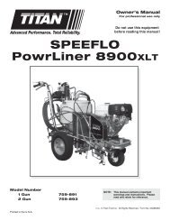
IntroductionCongratulations on having selected the finest airless sprayeravailable in the world. This <strong>Admiral</strong> represents the latest inairless technology. Its ability to efficiently apply a wide rangeof coatings makes it an excellent buy. We thank you for yourpurchase and welcome you to our large and growing family ofTitan users.Titan pumps are proven performers for all types of jobs. Thereare models for virtually any application, including architectural,finishing, industrial maintenance, corrosion control, cold appliedroofing, waterproofing and marine protective coatings. More than75,000 Titan pumps are in operation around the world, providingtheir owners with dependable, efficient operation.Pumps are specifically designed for easy application of today’slow VOC, high solids and abrasive coatings.Standard features assure superior reliability. Famous TitanSevere Service paint pumps and high efficiency air motors arestandard on all models.Severe Service paint pumps mean twice the life, half themaintenance.• Hard-chrome precision polished rods and cylinders givemaximum abrasion and corrosion resistance with minimumfriction. Result: long life.• Tungsten carbide valve seats with hardened stainlesssteel check balls prevent fluid cutting and resist plugging.Long-Life Packings are also standard.• Self adjusting, pressure compensated spring loadedpackings ensure proper seal and long life.• Standard packing sets of leather and UHMWPE (ultrahigh molecular weight polyethylene) provide the industry’slongest packing life.• Wiper seal on lower packings keeps abrasive materialsfrom hardening on cylinder wall.• Alternate packing materials are available fro specializedapplications.Standard air motor features include:High-efficiency -• Maximum output per cubic foot of air input.• More work with less air than competitive air motors.No motor icing -• Continuous operation without icing even at high cyclerates.• Oversized valving and exhaust porting.You have made an excellent choice. We know you will bepleased with your new <strong>Admiral</strong>. Thanks again for selectingTitan. We appreciate your business.<strong>Admiral</strong> SeriesVented shutoff valveAutomaticlubricatorAir pressure gaugeAir regulatorCart assemblyAir motorAir filter /moisture separatorGrounding lugPressure bleedvalveOutlet assemblyGun hose connectionBleed lineFluid pumpSiphon hose© Titan Tool Inc. All rights reserved. 5
SetupThe flow from the spray tip is at very high pressure.Contact with any body part may be dangerous. Donot place finger on gun outlet. Do not point thegun at any person.Read, understand, and follow all warnings beforestarting or operating this sprayer.5. Connecting the paint hoses:The siphon hose and the bleed line hose have factoryinstalled Teflon tape on the male end of the hoses.Tigthen the siphon hose and bleed line wrench tight.Required tools: Crescent wrench and screwdriver1. Compressor Requirements:Consult the Technical Specifications on each model forthe approximate air requirements.NOTE: The requirements will vary on each model.Proper grounding in important. This applies togas, electric and air powered models. The passageof some materials through the nylon hose will buildup a static electric charge, which if discharged,could ignite solvent vapors present and create anexplosion.2. Grounding the pump:Be sure the <strong>Admiral</strong> system is grounded. All Titan unitsare equipped with a grounding lug. A Grounding Clamp,Part No. 101-208 and Ground Wire, Part No. 101-212should be used to connect the unit to a true earth ground.These accessories can be ordered from your localdistributor.a. Loosen the Grounding Screw.b. Insert one end of the Grounding Wire into the slot in theGrounding Lug. Tighten the screw.c. Connect the other end of the Grounding Wire to a trueearth ground. Check local electrical regulations fordetailed grounding instructions.6. One Gun Operation:Attach the gun and hose. Always use a spray hose atleast 50 feet long. Do not use Teflon or thread sealant onthis assembly. Do not install the spray tip.7. Multiple Gun Operation:For models equipped with a second gun outlet, removethe plug from the outlet and connect a second hose andgun to the outlet.Multigun manifolds with shut-off valves can be used whenmore than two guns are needed. Never use this secondgun outlet for a one-gun operation.For guns without a second gun outlet, connect a multigunmanifold at the single gun outlet. These manifoldsare either 2, 3, or 4 gun manifolds with shut-off valves.Connect a hose and gun to each outlet.3. Ventilation:Areas must be well ventilated to prevent hazardousoperation with volatile solvents or exhaust fumes.4. Connecting compressor to the sprayer:Tighten the air hose wrench tight. The air hose hasfactory installed Teflon ape on the male end of the hose.See figure below.8. Fill the Wet-Cup 1/2 full with Titan’s Lubrisolv, suppliedby the factory. This extends packing life.9. Strain all paints with Titan’s 5 gallon Nylon strainer, PartNo. 160-500 or 1 gallon Nylon strainer, Part No. 160-100 to assure trouble-free operation and freedom fromfrequent cleaning of inlet screen and gun strainer.6 © Titan Tool Inc. All rights reserved.
Startup1. Close the self relieving shutoff valve. The figure belowshows the handle in the closed position.9. The Automatic Lubricator was set at the factory for thecorrect injection rate. Do not adjust the lubricator until it isnecessary to refill the reservoir. The lubricator is filled withAirCare lubricant. See figure below.2. Start the compressor.3. Drain the Petcock by pushing it off center.4. Adjusting the air regulator:The air motor is designed for a maximum air input of 120psi. Turn the T-Handle clockwise to increase pressureand counter-clockwise to decrease pressure. Verify theamount of air pressure by reading the air gauge.10. After refilling the reservoir, the automatic lubricator willneed adjusting. Turn the adjusting screw clockwiseto increase the AirCare injection rate and counterclockwiseto decrease it.Check the injection rate by observing the flow through thesight dome. The proper flow rate is 1 drop of AirCareper minute or every 90-125 cycles. In cold weather whenicing may occur, increase to one drop every 50-60 cycles.Operation at very high cycle rates (i.e. greater than 60) willrequire a higher AirCare injection rate.important: Use only Titan AirCare Part No. 311-011lubricant. Use of any detergent-type lubricants will cause aserious problem with the pump and void the warranty.11. Close the pressure bleed valve. The system is now underpressure.<strong>Paint</strong> pressure is directly proportional to the amount of airpressure.Example: <strong>Admiral</strong> 30:1100 psi reading at air gauge = 3000 psi at pump outlet.Consult the materials manufacturer for guidelines in establishingthe correct air pressure.NOTE: Using a higher pressure than required will onlywear out tips. Use the guidelines in establishingthe lowest pressures for proper atomization.Once the correct air pressure has been established, lock the airregulator by tightening the lock nut.5. Place the siphon hose in the compatible flushing fluid.A water soluble oil was used to test your new sprayer atthe factory. You must clean the system before spraying toavoid contamination of the sprayed material.• If you are spraying a water-based latex, flush with warmsoapy water followed by a clean water rinse.• If you are using any other coating, flush with warmsoapy water followed by a solvent. Check with thematerial manufacturer for a compatible solvent.6. Place waste container below bleed line.7. Open pressure bleed valve.8. Open self-relieving vented shutoff valve. The handleshould now be in line with the valve.© Titan Tool Inc. All rights reserved. 7
Operation1. Repeat above Startup procedure with paint material. Lockgun trigger and attach spray tip. See the Technical DataSheet on the gun provided for installation and selection ofthe proper tip size.2. Test spray pattern. Operate the pump at the lowest airgauge reading which provides good atomization.See the Troubleshooting guide if you are not getting theproper pattern.3. When restarting the unit, reduce the pressure at the airregulator and open the pressure bleed valve.Pressure Relief ProcedureAlways reduce fluid pressure when you arecleaning a clogged tip, changing a tip, servicingany part of the system, or shutting down. Followthe steps below.1. Engage the gun trigger lock.2. Close the self-relieving vented shutoff valve.3. Open the pressure bleed valve by turning it counterclockwisethree full turns.4. Disengage the gun trigger lock and hold trigger open untilflowof material stops.Cleaning a Clogged TipThe flow from the spray tip is at very high pressure.Contact with any body part may be dangerous. Donot place finger on gun outlet. Do not point thegun at any person. Never operate the spray gunwithout the proper tip guard.1. Follow the Pressure Relief Procedure outlined above.2. Lock the gun trigger.3. Unscrew the nozzle cap and remove the spray tip. Washthe tip in solvent and use a tip probe to remove anyclogged material.4. If the gun is equipped with a Titan TAC 5 Assembly, seeTechnical Data Manual 150:99 for instructions.5. Release the gun trigger lock and spray briefly into a wastecontainer to flush out any clogged particles.6. Reset the trigger lock in the “Trigger Locked” position.Release the trigger lock and resume spraying.Color Change / Clean Outimportant: Use only compatible solvents when cleaningout oil based enamels, lacquers, coal tar, and epoxies.Check with the fluid manufacturer for a recommendedsolvent.1. Reduce pressure by following the Pressure ReliefProcedure.The pressure bleed valve should be turned counterclockwisethree full turns.2. Pull the siphon tube out of the material container.3. Remove the spray tip from the gun. Hold the gun triggeropen until material flow stops.4. Put siphon tube into wash solvent or water as applicable,and operate pump slowly at low pressure until solventflows freely from pressure bleed valve line.5. Close pressure bleed valve and hold gun trigger openuntil solvent flows freely from gun. If solvent is not toodirty, recirculate it by flowing gun stream back into solventcontainer. Use additional clean solvent and repeatprocedure if necessary.6. If your model is equipped with a gun strainer screen andpump outlet filter, check them daily. Use 50 mesh screenswith spray tip size .018 and larger. Use 100 or 200 meshscreens with spray tip sizes .015 and smaller. Alwayscheck the materials manufacturer’s recommendations forproper filtration requirements.7. On models with a outlet paint filter, replace paint filter capby turning clockwise. The filter cover should be handremovable after the first or second use with a new TeflonO-ring.important: O-ring must have Teflon backup washer toseal properly.8. If unit has been spraying a water soluble material, flushwith water and then repeat procedure with mineral spiritsor similar solvent.9. Wash spray tip and preorifice in solvent. Blow tip cleanwith air pressure directed through the tip in the reversedirection. Store preorifice and tips in clean place.8 © Titan Tool Inc. All rights reserved.
Air Motor MaintenanceAir motors require a normal maintenance and service inspectionat 1500 hours service. Service procedure includes replacementof motor service kit, minor. It is suggested that one motorservice kit, major (which includes the minor kit) be kept on handfor normal maintenance and emergency repairs. Check theindividual model’s specifications for correct part numbers.Air motors should be served with moisure free air and for this, anairline filter / moisture separator, such as Titan Part No. 141-057is recommended. Very cold and humid air conditions combinedwith high speed and high operating pressure may require amoisture separator and an automatic lubricator to avoid icing.NOTE: An air line filter / moisture separator are standardon many models.Best lubrication will be obtained with an automatic lubricator suchas Titan Part No. 151-055.Fluid Pump MaintenanceIf the fluid pump is going to be out of service for an extendedperiod of time, it is recommended that following cleanup, akerosene and oil mixture be introduced as a preservative.Packings may tend to dry out from lack of use. The is particularlytrue of the upper packing set for which upper packing lubricant,Lubrisolv, Titan Part No. 310-200, is recommended in normalusage. A sample of Lubrisolv accompanies each new unit. Donot substitute water or paint solvent for Lubrisolv. Ordinary oilmay contaminate the paint material and is not recommended.If the fluid pump has been out of service for an extended periodof time, it may be necessary to prime the suction by pouringsome of the paint solvent into the inlet siphon tube to restart.important: It is very important that the threads on theinlet siphon hose coupling are properly sealed. Any airleakage will produce erratic operation of pump and maydamage the system.The up and down strokes should be approximately equal intime. That is, one should not be faster than the other. A fast upor down stroke may indicate air in the system or malfunctioningvalve seats. See Troubleshooting guide.Hydraulic Motor and <strong>Paint</strong> Pump ServiceSee the individual Technical Data Manual Sheets formaintenance and service instructions on the reciprocatinghydraulic motor and for mechanical service and maintenance onthe fluid pump.© Titan Tool Inc. All rights reserved. 9
Troubleshooting - Airless SprayingCondition Possible Cause CorrectionA. Poor spray pattern and / or tails attop and bottom of the spray pattern.B. The gun drips or throws a drop atthe beginning or end of the spraypattern.Worn or incorrect tip and/or insufficientatomization.Hose size or length is too small or toolong.Dirty filter.Needle may not be seating correctly.Increase spring tension.C. Spray tip stops up frequently. Particles too large for spray tip are passingfilter and/or gun screen.D. Spray pattern changes with pumpcycle.E. Irregular flow of material. Onestroke faster than the other.Restrictions in the fluid system.Packings are worn or valve balls are notseating.Restriction in the siphon system.F. Spitting. Air in system.Dirty gun.G. Gun does not spray any fluid. Suction hose leak.No paint.Plugged foot valve.Plugged filters or tip.Ball check valve stuck open.Troubleshooting - Spray PatternsCondition Possible Cause CorrectionBe sure the tip is not worn. Increasepressure. Lower viscosity. Reducesurface tension by increasing hose size tominimize pressure drop through hose and/or reduce hose lengths. Use preorificedisc (H disc).Needle-orifice combination should befactory relapped. Needle packing maybe too tight. Loosen as much as possiblewithout leakage.Turn adjusting screw on back of gunclockwise to increase tension or use thegreen HP spring Part # 701-098.Use 100 mesh gun screen instead of 50mesh for small spray tips. Use 100 meshscreen in pump filter. Strain paint.Check gun and pump filter screens.Always clean screens before they load up.Check siphon hose assembly to be sure noair is entering, then recheck all threadedfittings for leakage. See Troubleshooting- Fluid Section for additional serviceinformation.Inspect for siphon hose leak.Disassemble and clean gun.Inspect for siphon hose leak.Check fluid supply.Remove, clean, inspect foot valve.Clean filters or tip.Clean and inspect pump ball check valve.A. Tails Inadequate fluid delivery.Fluid not atomizing correctly.Increase fluid pressure. Change to smalltip orifice size. Reduce fluid viscosity.Reduce hose length.Clean gun and filter(s). Reduce number ofguns using pump.B. Hour glass Inadequate fluid delivery. Same as above.C. Distorted Plugged or worn nozzle tip. Clean or replace nozzle tip.D. Pattern expanding and contracting(surge)Suction leak.Pulsating fluid delivery.E. Round pattern. Worn tip.Fluid too heavy for tip.Inspect for siphon hose leak.Change to a smaller tip orifice size.Install pulsation dampener in system ordrain existing one. Reduce number ofguns using pump.Remove restrictions in system, clean tipscreen if filter is used.Replace tip.Increase pressure. Thin material. Changenozzle tip.10 © Titan Tool Inc. All rights reserved.
Troubleshooting - Air MotorCondition Possible Cause CorrectionA. Motor stops at top or bottom ofstroke - air does not exhaust whengun is open.Piston rod is loose where it connects to thefluid section.Trip springs or valve spring broken.Tighten connection.Inspect and replace where neessary.B. Motor stops, blows air from exhaustwhen gun is open.Motor is frozen due to icing or lack oflubrication.See above.Air valve is in dead stall position.O-rings were worn or damaged.Troubleshooting - Fluid SectionsCondition Possible Cause CorrectionA. Pump delivers on upstroke onlyor goes up slowly and down fast(commonly called downstroke dive).B. Pump delivers on down stroke onlyor goes up fast and down slowly.Lower foot valve ball is not seating due totrash or wear.Material to viscous to siphon.Air leaking in on siphon side or damagedsiphon hose. Siphon may be too small forheavy material.Upper packing nut (if applicable) is looseor upper packings are worn.Upper ball is not seating due to trash orwear.Lower packing set is worn.Add 30 weight nondetergent oil to manualoiler. If condition persists, install moistureseparator and automatic lubricator.See above.Remove one trip spring retainer, trip springand ball. Push spool valve up or down,lubricate, reassemble and restart.Install minor service kit and followinstructions in General Maintenance andService section of manual.If dust or dirt is found inside motor, checkair supply for contamination.Remove foot valve assembly. Clean andinspect. Test foot valve by filling withwater. If ball fails to seal the seat, replaceball.Thin material - contact manufacturer forproper thinning procedures.Tighten all connections between pumpand paint container. If damaged, replace.Switch to bigger siphon set.If tightening upper packing nut does notcorrect, change upper packings.Check upper seat and ball with water. Ifball fails to seal seat, replace.Replace packing set is worn.C. Pump moves up and down fast, notdelivering material.D. Pump moves up and down slowlywhen spray gun is shut off.Material container is empty or material istoo thick to flow through the siphon hose.Bottom ball stuck to foot valve seat.Siphon hose is kinked or loose.Loose connections. Bleed valve is openpartially or bleed valve is worn. Lowerpacking set is worn.Upper and/or lower ball not seating.E. Not enough fluid pressure at gun. Spray tip is worn.Compressor (air operated units only) toosmall. Outlet filter or gun filter is clogged.Low voltage and/or inadequate amperage.Hose size or length is too small or toolong.F. Pump chatters on up or down stroke Solvent has caused upper packing toswell, or packing is too tight.Refill with new material. If too thick,remove siphon hose and immerse pump oradd thinner to material. Change to biggersiphon set. Open bleed valve to remove airand restart pump.Remove foot valve. Clean ball and seat.Straighten.Check all connections between pump andgun. Tighten as necessary. If material isflowing from bleed hose, close bleed valveor replace if necessary. Should none ofabove be evident, replace lower packing.Reset balls by cleaning.Replace.Clean or replace filter. Recommend properhose size and/or air compressor size.Check electrical service. Correct as required.Increase hose size to minimize pressuredrop through hose and/or reduce hoselengths.Back off upper packing nut 1/4 turn (ifapplicable) and restart pump. Repeat ifnecessary.© Titan Tool Inc. All rights reserved. 11
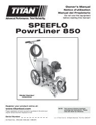
<strong>Admiral</strong> Series Portable Models213856271384712 © Titan Tool Inc. All rights reserved.
<strong>Admiral</strong> Series Portable ModelsAll models with heavy duty cart 30:1 40:1 60:1Item No. Part No. Description 830-451 941-421 941-441 860-451 860-4611 850-245850-557142-104245-556Motor pump assemblyAir motorAssembly setFluid pump assembly11a 850-185850-555142-100185-5511b 860-559850-555142-102155-559Motor pump assemblyAir motorAssembly setFluid pump assemblyMotor pump assemblyAir motorAssembly setFluid pump assembly1 11 12 928-835 Airline assembly, 3/4” 1 1 1 1 13 590-301 Cart assembly, heavy duty 1 1 1 1 14 840-205 Outlet assembly, 1/2” 1 1 15 920-554 Filter assembly, outlet 15a 920-605 Filter assembly, outlet manifold, 6000 psi 16 840-209 Bleed line assembly w/valve 1 17 103-807 Siphon hose assembly, 1” w/filter screen 1 1 17a 103-810 Siphon hose assembly, 1” w/strainer 1 18 219-100 Mounting kit 1 18a 219-200 Mounting kit 1 1 1© Titan Tool Inc. All rights reserved. 13
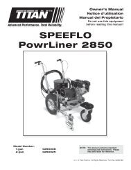
<strong>Admiral</strong> Series Wall Mount and Drum Mount Models2145681293614 © Titan Tool Inc. All rights reserved.
<strong>Admiral</strong> Series Wall Mount and Drum Mount Models30:1 40:1 60:1WallMountDrumMountWallMountWallMountWallMountItem No. Part No. Description 830-331 941-183 941-331 941-431 860-3551 850-245850-557142-104245-556Motor pump assembly, drum mountAir motorAssembly setFluid pump assembly11a 850-187850-555183-101185-5511b 850-186850-555142-101181-5561c 850-185850-555142-100185-5511d 860-559850-555142-102159-559Motor pump assemblyAir motorAssembly setFluid pump assemblyMotor pump assemblyAir motorAssembly setFluid pump assemblyMotor pump assemblyAir motorAssembly setFluid pump assemblyMotor pump assemblyAir motorAssembly setFluid pump assembly2 928-835 Airline assembly, 3/4” 1 1 1 1 13 219-600 Drum cover assembly, 55 Gal. 14 590-300 Bracket assembly, wall mount 1 1 1 15 219-504 Plate, adapter 16 840-205 Outlet assembly, 1/2” 16a 920-605 Filter assembly, outlet 17 920-554 Filter assembly, outlet 17a 920-556 Filter assembly, outlet 1 18 840-209 Bleed line assembly w/valve 1 1 1 19 103-806 Siphon hose assembly, 3/4” w/rock catcher 1 19a 103-808 Siphon hose assembly, 1” w/filter screen 1 11111© Titan Tool Inc. All rights reserved. 15
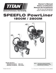
<strong>Admiral</strong> 850-555 and 850-557 Air Motor121718193332021222324252627344283391011128571461316152930313238394140353637ItemNo.PartNo.Description850-555 850-557QTY.QTY.1 818-010 Elbow 1 12 738-026 Bolt 8 83 742-007 Adapter 4 44 742-943 Air line 2 25 850-997 Head, cylinder 1 16 928-103 Adapter 2 27 850-967 Plate, exhaust 2 28 862-701 Nut 2 29 138-340 Ball 2 210 738-213 Spring, trip 2 211 742-001 O-ring 2 212 742-905 Retainer, trip spring 2 213 742-913 Sleeve, valve 1 114 742-223 O-ring 4 415 858-611 Nut 2 216 858-660 Screw 2 217 858-812 Nut, stop 1 118 738-218 Keeper, upper valve 1 119 740-925 Valve 1 120 738-224 O-ring 2 221 740-985 Keeper, lower valve 1 1ItemNo.PartNo.Description850-555 850-557QTY.QTY.22 742-011 Bushing 1 123 742-223 O-ring 1 124 890-114 O-ring 1 125 742-016 Clip, retainer 1 126 738-985 Nut, piston 1 127 742-005 Washer, piston 1 128 743-011 Valve rod assembly 1 129 850-917 PIston 1 130 850-016 O-ring 1 131 743-227 Collar, valve trip 1 132 738-937 Rod, piston 1 133 850-004 Gasket 2 234 850-952 Cylinder 1 135 738-021 O-ring 1 136 742-224 Ring, wear 1 137 850-947 Base, motor 1 138 101-205 Lug, ground 1 139 858-624 Screw 1 140 862-701 Nut 8 841 138-007 Nut, coupling 141a 138-017 Nut, coupling 116 © Titan Tool Inc. All rights reserved.
Air Motor Service ProcedureThis Air Motor requires a normal mantenance inspection at 1500hours of service on the non-circulating models and 800 hours ofservice on the circulating models. Service procedure includesreplacement of the Motor Service Kit, Minor Part # 850-050 listedbelow. It is suggested that one Motor Service Kit, Major Part# 850-550 (which includes the minor kit) be kept on hand fornormal maintenance and emergency repairs.MaintenanceThe 850 Series Air Motor should be served with moisture-freeair. A water trap, Titan Part #141-057, is recommended. For useunder very cold and humid conditions a moisture separator andan automatic oiler may be necessary to avoid icing.Disassembly Procedure1. Disconnect air hose from elbow (1).2. Remove locking bolts and nuts (15, 16), trip springretainers (12), O-rings (11), trip springs (10), and balls (9)from both sides of the cylinder head (5).3. Disconnect air line (4) from adaptors (3) top and bottom.4. Remove eight nuts (40) and eight bolts (2).5. With piston (29) in down position, place wrench on flatsof piston rod (32) and disconnect piston rod from pumpconnecting rod.6. With piston (29) at top of stroke, raise cylinder head (5)and remove retainer (25). Lift off cylinder head (5). Valvesleeve (13) may pull out of cylinder head. If so, lift valvesleeve off separately.7. Remove stop nut (17) and then unthread upper valvekeeper (18).8. Remove air valve (19) followed by lower valve keeper (21)and bushing (22).9. If valve sleeve (13) is still in cylinder head, leave it thereunless it is necessary to change O-rings. To remove, useSleeve Removal Tool Part # 900-021 to remove sleeve(13).10. Remove cylinder (34).11. Remove piston rod (32) and piston (29) from motor base(37).12. Secure piston (29) in vise and remove piston nut (26) andpiston washer (27).important: Do not clamp on O.D. of the piston.13. Remove valve rod assembly (28) and valve trip collar (31).14. Unscrew piston rod (32) from piston (29).15. Remove O-ring (30) from piston (29).16. Remove O-rings (23, 24) from bushing (22), O-ring (35)and wear ring (36) from motor base (37).Reassembly ProcedureWash all replaceable parts thoroughly with kerosene andlubricate with Lubri-Plate or similar non-water soluble grease.For routine servicing, use new parts from the Air Motor ServicKit Part # 850-500. Inspect all other parts for abnormal wear ordamage and replace if necessary.1. Install new O-ring (35) and new wear ring (36) into motorbase (37) and new O-rings (23, 24) into bushing (22). Usecare to avoid damaging O-rings and make sure they areproperly seated in the O-ring grooves.2. Place valve trip collar (31) into piston rod (32) followed byvalve rod assembly (28).3. Screw piston rod (32) into piston (29). Replace piston nutand washer (26, 27).4. Install new piston O-ring (30) into piston (29).5. Place new gasket (33) into position in motor base (37).6. Place piston assembly (29, 32) into motor base (37). Donot damage O-ring.7. Place new O-rings (20) on air valve (19).8. Mount air valve assembly onto valve rod (29) by placingbushing (22) over valve rod (28), followed by keeper (21),air valve (19) and upper valve keeper (18). Thread uppervalve keeper (18) down on air valve hand tight. Thenloosen approximately 1/4 turn. Place wrench on flats ofvalve rod (28) and hold to prevent valve rod (28) fromturning. Thread stop nut (17) down on valve rod (28) tolock upper valve keeper (18) in position. Be sre uppervalve keeper (18) does not change position.9. Grease inside of cylinder (34) and work cylinder downover piston gently in order to avoid damage to pistonO-ring (30).10. Install new O-rings (14) on valve sleeve (13). Greasevalve sleeve and install into cylinder head (5) so largeholes in sleeve line up with trip retainer holes in cylinderhead (5). Put one trip retainer (12) with new O-ring (11)into cylinder head without ball (9) or spring (10) and holdin position temporarily with locking bolt (16) and nut (15).11. Place new gasket (33) into position in cylinder head (5)and hold with gasket cement or grease.12. Carefully position air valve assembly up into cylinder head(5).13. Push bushing (22) up into bottom of cylinder head (5) tosufficiently permit installation of retainer (25).14. To install trip spring retainer be sure one of the detentsof valve (19) is properly lined up with hole in the cylinderhead (5). Place new trip spring retainer O-ring (11) ontoremaining trip spring retainer (12). Install new ball (9)followed by trip spring (10) and trip spring retainer (12) intohole of cylinder head (5). Lock into position with bolt (16)and nut (15).15. For opposite trip spring retainer (12) replacement, repeatstep #14.16. Connect air line (4) to adapters (3) top and bottom.17. Replace bolts (2) and nuts (40). Always tighten nuts180 degrees apart in order to obtain proper and evencompression.18. Place wrench on the flats of piston rod (32) and connectpump connecting rod.19. Reconnect air hose to elbow (1).Service KitsPart No. Description743-012 Valve rod and spring assemblyIncludes items 17, 28 and 31850-050 Motor service kit, minorIncludes items 9-11, 14, 17, 20, 23-24. 30, 33, 35-36.850-500 Motor service kit, majorIncludes minor service kit 850-050, and items 13,18-19, 21, 28 and 31.742-942 Air line assemblyIncludes item 4, and compression nut, part #742-009 and ferrule, part # 742-010 (each is acomponent of item 3, adapter part # 742-007).© Titan Tool Inc. All rights reserved. 17
<strong>Admiral</strong> 155-559 Fluid Pump AssemblyItemNo.PartNo.DescriptionQTY.1 431-007 Nut, coupling *42 155-907 Block, pump 13 155-053 Packing set, Poly/Lthr. 2195114 155-906 Upper packing spring 15 155-010 Washer 11816126 155-982 Rod, displacement 17 155-009 Washer, piston 18 155-001 Lower packing spring 19 155-225 Ball, S.S. 110 155-921 Piston seat assembly 1202781111 891-373 O-ring 212 155-932 Cylinder 113 174-113 Stop, ball 114 174-102 Cage, ball 115 178-700 Ball, S.S. 11316 155-991 Valve, foot 1321223910141516142-102 Assembly SetItemNo.PartNo.DescriptionQTY.18 140-016 Stanchion 219 441-956 Rod, connecting 120 868-101 Nut 121 870-004 Washer 622 870-401 Nut 2DisplacementRodStroke Length Displacement Volume /StrokeDisplacement Volume / 40 Cycles/ 80 StrokesIN 2 CM 2 IN CM IN 3 CM 3 LITER IN 3 GAL. CM 3 LITER.976 6.3 4 10.2 3.9 63.9 .0639 312 1.35 5113 5.113MotorSelectionMotor Pumpratio850 Series 60:118 © Titan Tool Inc. All rights reserved.
155-559 Fluid Pump Service Informationimportant: Use of non-Titan manufactured service partsmay void warranty.The 155 Series Pump should receive a routine servicing afterapproximately 1000 hours of use or earlier if there is excessiveleakage from the top packing, or if pump strokes become fasteron one stroke or another. The use of Titan Lubrisolv Part #310-200 is recommended as an upper packing lubricant. donot substitute oil, water or solvent for an upper packinglubricant.Disassembly Procedure1. Remove siphon hose assembly.2. If the pump is connected to air motor, hold motor pistonrod at wrench flats and unthread coupling nut (1) toseparate pump from motor.3. Unthread and remove foot valve (16) and pump cylinder(12) to separate from pump block (2) and remove ball (15),ball stop (13), ball cage (14) and O-ring (11).4. Secure piston seat assembly (10) in a vise and unthreaddisplacement rod (6) to remove packing set (3), spring (8)and washer (7).5. Inspect and clean all parts. Reject cylinder (12) and/ordisplacement rod (6) if hard chrome is grooved or wornthrough to gray metal.Reassembly ProcedureService KitsItemNo.PartNo.Pump service kits, minorDescription155-0513 155-052 Packing set, leather 2155-0553a 155-053 Packing set, Leather/Poly 29 155-225 Ball, S.S. 1 111 891-373 O-ing 2 215 178-700 Ball, S.S. 1 1ItemNo.426-051 Loctite sealant 1 1PartNo.Pump service kits, majorDescription155-051155-051 Minor service kit 1155-055155-055 Minor service kit 16 155-981 Rod, displacement 1 112 155-932 Cylinder 1 1NOTE: If cylinder (12) and displacement rod (6) arereusable, then only a minor kit part # 155-051 or155-055 may be required for reassembly.1. Place new packing set (3) over piston seat (10) with “V”packings point downward (V) and reassemble with ball(9), spring (8),washer (7) and displacement rod (6) in thatorder. Tighten and use Loctite on clean threads.2. Insert new upper packing set (3) into pump block (2).important: Peak of “V” packings must point upwards onreassembly.Install upper packing spring (4) and washer.3. Insert displacement rod assembly (6) through pump block(2) holding upper packing set (3) in place with fingers.4. Lubricate the threaded ends of cylinder (12) including theO-rings (11) to protect them on reassembly.5. Thread cylinder (12) into pump block (2). Do notovertigthen.6. Replace ball (15), ball cage (14) and ball stop (13) intofoot valve (16) and thread into cylinder (12). The O-rings(11) should be lubricated to protect it on replacement offoot valve. It is not necessary to overtighten as seal isobtained when parts are fully threaded together.NOTE: It is not necessary to overtighten foot valve andcylinder into pump block. O-ring seals performsealing function without excessive tightening.Full thread engagement is sufficient. The footvalve may be rotated back up to 1/2 turn from fullengagement for convenient hose position.NOTE: For siphon hose attachment, it is criticallyimportant that the threads of the siphon hose fitsnugly into the foot valve with the hose assemblycouplings Teflon taped and sealed to prevent airinlet leakage.© Titan Tool Inc. All rights reserved. 19
<strong>Admiral</strong> 181-556 Fluid Pump AssemblyItemNo.PartNo.DescriptionQTY.1 185-981 Pin, roll 123252 185-984 Rod, displacement 13 181-906 Block, pump 14 175-001 Upper packing set, Lthr. 1245 182-906 Spring, packing 16 228-002 Nipple, hex 1127 182-007 O-ring, Teflon 18 185-011 Retainer, spring 19 185-010 Spring, packing 12234510 180-002 Lower packing set, Lthr. 111 182-921 Seat, piston 112 182-932 Cylinder 113 174-113 Stop, ball 114 174-102 Cage, ball 115 178-700 Ball, S.S. 116 155-981 Valve, foot 121206717 742-223 O-ring, Buna 118 174-001 O-ring, Teflon 119 920-103 Ball 119181789101112131415142-101 Assembly SetItemNo.PartNo.DescriptionQTY.20 868-101 Nut 221 870-004 Washer 222 870-005 Washer, spacer 423 140-016 Stanchion 224 441-956 Rod, connecting 125 138-007 Nut, coupling ** Not included in this assembly16DisplacementRod AreaStroke Length Displacement Volume /StrokeDisplacement Volume / 40 Cycles/ 80 StrokesIN 2 CM 2 IN CM IN 3 CM 3 LITER IN 3 GAL. CM 3 LITER1.38 8.90 4 10.2 5.55 90.9 0.091 444 1.92 7272 7.27MotorSelectionMotor Pumpratio850 Series 40:120 © Titan Tool Inc. All rights reserved.
181-556 Fluid Pump Service Informationimportant: Use of non-Titan manufactured service partsmay void warranty.The 181 Series Pump should receive a routine servicing afterapproximately 1000 hours of use or earlier if there is excessiveleakage from the top packing, or if pump strokes become fasteron one stroke or another. The use of Titan Lubrisolv Part #310-200 is recommended as an upper packing lubricant. donot substitute oil, water or solvent for an upper packinglubricant.Disassembly Procedure1. Test pump before disassembly. Follow test procedure inTroubleshooting Guide - Fluid Section.2. Remove siphon hose assembly.3. Remove stanchion nuts (20) and washers (21).4. If the fluid section is connected to an air motor, hold the airmotor piston rod at the wrench flats and unthread couplingnut (25) to separate pump from motor.If the motor is connected to a hydraulic motor, removeallen set screw between the two flats on hydraulic motorrod. Hold the hydraulic motor rod at the wrench flatsand unthread coupling nut (25) to separate pump fromhydraulic motor.important: Never use a pipe wrench, pliers, etc. on thechrome part of hydraulic, air or fluid section rod.5. Remove roll pin (1) on connecting rod (24). Removeconnecting rod from displacement rod (2).6. Unthread and remove foot valve (16).7. Remove Teflon O-ring (18), Buna O-ring (17), ball stopring (13), ball cage (14) and ball (15).8. Remove cylinder (12).9. Remove displacement rod (2).10. Place piston seat (11) in a vise and use a wrench on theflats to remove the displacement rod (2) from the pistonseat (11).11. Remove lower packing set (10), spring (9), spring retainer(8) and ball (19).12. Remove upper packing spring (5), O-ring (7) and packingset (4) from pump block (3).13. Clean and inspect all parts. Inspect rod or pump tube’shard chrome for grooves, dents or worn areas. Replace ifhard chrome is damaged. Inspect valve seats and replaceif cracked or worn.8. Insert ball (15), ball cage (14), ball stop retainer ring (13),Buna O-ring (17) and Teflon O-ring (18) into foot valve.important: Lubricate all O-rings.9. Thread foot valve (16) back into cylinder (12).NOTE: It is not necessary to overtighten foot valve andcylinder into pump block. O-ring seals performsealing function without excessive tightening.Full thread engagement is sufficient. The footvalve (16) may be rotated back up to 3/4 turn fromfull engagement for convenient hose position.10. Insert coupling nut (25) back onto connecting rod (24) andthread connecting rod (24) back onto displacement rod(2).Service KitsItemNo.Pump service kit, minor (Part # 182-050)PartNo.DescriptionQTY.4 175-001 Packing set, leather 17 182-007 O-ring, Teflon 110 180-002 Packing set, leather 115 178-700 Ball 117 742-223 O-ring 118 174-001 O-ring, Teflon 119 920-103 Ball 1ItemNo.Pump service kit, major (Part # 182-520)PartNo.DescriptionQTY.182-050 Pump service kit, minor 12 185-984 Rod, displacement 111 182-921 Seat, piston 112 182-932 Cylinder 1Reassembly Procedure1. Insert upper packing set (4) into pump block (7)important: Peak of “V” packings must point upwards onreassembly.2. Insert upper spring (5); small end of spring must go towardthe packing set.3. Place packing set (10) over piston seat (11).important: Peak of “V” packings must point downwardon reassembly.4. Replace spring (9), spring retainer (8) and ball on pistonseat (11).5. Thread seat back onto displacement rod (2).important: Use Loctite on clean threads.6. Insert displacement rod (2) assembly through upperpacking set (4) in pump block (3).7. Place O-ring (7) on end of cylinder (12) and thread backinto pump block (3).important: Lubricate all O-rings before assembly.© Titan Tool Inc. All rights reserved. 21
<strong>Admiral</strong> 185-551 Fluid Pump AssemblyItemNo.PartNo.DescriptionQTY.1 185-981 Pin, roll 1222 185-984 Rod, displacement 13 181-906 Block, pump 114 178-001 Packing set, upper 1235 228-002 Nipple, hex 16 182-906 Spring, packing 17 182-007 O-ring, Teflon 1214568 183-930 Cylinder 19 185-011 Retainer, spring 110 185-010 Spring, packing 111 180-001 Packing set, lower 12012 920-103 Ball 113 182-921 Seat, piston 114 183-230 O-ring, Buna N 12315 182-007 O-ring, Teflon 116 183-992 Valve, foot 1717 314-180 Ball 1818 240-022 Cage, ball 191018a 241-109 Pin 1142-100 Assembly Set111213ItemNo.PartNo.DescriptionQTY.19 870-401 Nut 220 870-004 Washer 621 140-016 Stanchion 222 442-956 Rod, connecting 11415868-101 Nut (not shown) 1183-101 Assembly Set** (for 55 gallon drumcover)1617ItemNo.PartNo.DescriptionQTY.19a 870-401 Nut 220 870-004 Washer 621a 314-024 Stanchion 222 442-956 Rod, connecting 122a 180-979 Extension, connectingrod123 868-101 Nut 124 840-214 Riser pipe assembly 1** Not shownDisplacementRod AreaStroke Length Displacement Volume /StrokeDisplacement Volume / 40 Cycles/ 80 StrokesIN 2 CM 2 IN CM IN 3 CM 3 LITER IN 3 GAL. CM 3 LITER1.38 8.90 4 10.2 5.55 90.9 0.091 444 1.92 7272 7.27MotorSelectionMotor Pumpratio850 Series 40:122 © Titan Tool Inc. All rights reserved.
185-551 Fluid Pump Service Informationimportant: Use of non-Titan manufactured service partsmay void warranty.The 185 Series Pump should receive a routine servicing afterapproximately 1000 hours of use or earlier if there is excessiveleakage from the top packing, or if pump strokes become fasteron one stroke or another. The use of Titan Lubrisolv Part #310-200 is recommended as an upper packing lubricant. donot substitute oil, water or solvent for an upper packinglubricant.Disassembly Procedure1. Test pump before disassembly. Follow test procedure inTroubleshooting Guide - Fluid Section.2. Remove siphon hose assembly.3. Remove stanchion nuts (19) and washers (20).4. Hold the air motor piston rod at the wrench flats andunthread coupling nut to separate pump from motor.important: Never use a pipe wrench, pliers, etc. on thechrome part of hydraulic, air or fluid section rod.5. Remove roll pin (1) or jam nut on connecting rod (22).Remove connecting rod (22) from displacement rod (2).6. Unthread and remove foot valve (16).7. Remove Teflon O-ring (15), Buna O-ring (14), ball cageassembly (18) and ball (17).8. Remove cylinder (8).9. Remove displacement rod (2).10. Place piston seat (13) in a vise and use a wrench on theflats to remove the displacement rod (2) from the pistonseat (13).11. Remove lower packing set (11), spring (10), springretainer (9) and ball (12).12. Remove upper packing spring (6), packing set (4) andO-ring (7).13. Clean and inspect all parts. Inspect displacement rod’s(2) and cylinder’s (8) chrome for grooves, dents or wornareas. Replace if hard chrome is damaged. Inspect valveseats and replace if cracked or worn.Reassembly Procedure1. Insert upper packing set (4) into pump block (3)important: Peak of “V” packings must point upwards onreassembly.2. Insert upper spring (6); small end of spring must go towardthe packing set.3. Insert spring retainer (9).4. Place new lower packing set (11) over piston seat (13).important: Peak of “V” must point downward onreassembly.5. Replace spring (10), spring retainer (9) and new ball (12)on piston seat (13).6. Thread piston seat (13) back onto displacement rod (2).important: Use Loctite on clean threads.7. Insert displacement rod (2) assembly through upperpacking set (4) in pump block (3).8. Place new O-ring (7) on end of cylinder (8) and threadback into pump block (3).important: Lubricate all O-rings before assembly.9. Insert new ball (17), ball cage (18), and new Buna O-ring(14) into foot valve.NOTE: Ball cage pin (18a) to be in lower position unlesspump is to be used for heavy block filler orroofing materials.10. Place new Teflon O-ring (15) on cylinder (8) and theninstall foot valve assembly (16)NOTE: It is not necessary to overtighten foot valve andcylinder into pump block. O-ring seals performsealing function without excessive tightening.Full thread engagement is sufficient. The footvalve (16) may be rotated back up to 3/4 turn fromfull engagement for convenient hose position.11. Insert connecting rod (22) through coupling nut and threadconnecting rod (22) into displacement rod (2).12. Insert roll pin (1) into connecting rod (22).For siphon hose attachment, it is critically important thatthe thread of the siphon hose fit snugly into the foot valvewith the hose assembly couplings Teflon-taped and sealedto prevent air inlet leakage.Service KitsNOTE: Minor service kit # 185-050 has polyethylene/leather packings.Minor service kit # 180-051 has leather packings.Minor service kit # 185-052 has Teflon packings.ItemNo.Pump service kit, minor CTR IND TFLPartNo.Description185-050185-0514 175-001 Packing set, upper 14 178-001 Packing set, upper 1185-0524 178-320 Packing set, upper 17 182-007 O-ring, Teflon 1 1 111 180-002 Packing set, lower 111 180-322 Packing set, lower 111 183-001 Packing set, lower 112 920-103 Ball 1 1 114 183-230 O-ring 1 1 115 182-007 O-ring, Teflon 1 1 117 314-180 Ball 1 1 1ItemNo.426-051 Loctite Sealant 1 1 1Pump service kit, major CTR IND TFLPartNo.Description185-500185-050 Minor kit 1185-501185-051 Minor kit 1185-502185-052 Minor kit 12 182-984 Displacement rod 1 1 16 182-906 Spring, packing 1 1 18 183-930 Cylinder 1 1 1© Titan Tool Inc. All rights reserved. 23
<strong>Admiral</strong> 245-556 Fluid Pump Assembly12345678910111212131424232218171615ItemNo.PartNo.DescriptionQTY.1 245-907 Block, pump 12 240-001 Packing set, Poly/Lthr. 13 245-005 Packing spring, upper 14 245-013 Retainer, spring 15 892-323 O-ring, Telfon 16 245-012 Cylinder 17 920-103 Ball, S.S. 18 245-020 Retainer, spring 19 245-014 Spring, packing 110 240-001 Packing set, Poly/Lthr 111 241-007 Seat, piston 112 240-022 Cage, ball 112a 241-109 Pin, ball stop 113 891-403 O-ring, Teflon 114 892-281 O-ring, Buna 115 245-018 Valve, foot 116 314-180 Ball, S.S. 117 245-021 Retainer, cage 118 245-009 Rod, displacement 1ItemNo.PartNo.Description142-10419 870-401 Nut 220 870-004 Washer 621 140-016 Stanchion 222 245-109 Roll pin 123 442-959 Connecting rod 124 138-007 Nut, coupling ** Not included in this assemblyDisplacementRod AreaStroke Length Displacement Volume /StrokeDisplacement Volume / 40 Cycles/ 80 StrokesIN 2 CM 2 IN CM IN 3 CM 3 LITER IN 3 GAL. CM 3 LITER2.08 13.42 4 10.2 8.38 137.32 0.137 670 2.9 10.986 11MotorSelectionMotor Pumpratio850 Series 30:124 © Titan Tool Inc. All rights reserved.
245-556 Fluid Pump Service Informationimportant: Use of non-Titan manufactured service partsmay void warranty.The 245 Series Pump should receive a routine servicing afterapproximately 1000 hours of use or earlier if there is excessiveleakage from the top packing, or if pump strokes become fasteron one stroke or another. The use of Titan Lubrisolv Part #310-200 is recommended as an upper packing lubricant. donot substitute oil, water or solvent for an upper packinglubricant.Disassembly Procedure1. Test pump before disassembly. Follow test procedure inTroubleshooting Guide - Fluid Section.2. Remove siphon hose assembly.3. Remove stanchion nuts (19) and washers (20).4. If the fluid section is connected to an air motor, hold the airmotor piston rod at the wrench flats and unthread couplingnut (24) to separate pump from motor.If the fluid section is connected to a hydraulic motor,remove allen set screw between the two flats on hydraulicmotor rod. Hold the hydraulic motor rod at the wrenchflats and unthread coupling nut (24) to separate pumpfrom hydraulic motor.important: Never use a pipe wrench, pliers, etc. on thechrome part of hydraulic, air or fluid section rod.5. Remove roll pin (22) or jam nut on connecting rod (23).Remove connecting rod (23) from displacement rod (18).6. Unthread and remove foot valve (15).7. Remove Teflon O-ring (13), Buna O-ring (14), ball cageretainer (17), ball cage (12) and ball (16).8. Remove cylinder (6).9. Remove displacement rod (18).10. Place piston seat (11) in a vise and use a wrench on theflats to remove the displacement rod (18) from the pistonseat (11).11. Remove lower packing set (10), spring (9), spring retainer(8) and ball (7).12. Remove upper spring retainer (4), spring (3), Teflon O-ring(5) and packing set (2).13. Clean and inspect all parts. Inspect rod’s and cylinder’shard chrome for grooves, dents or worn areas. Replace ifhard chrome is damaged. Inspect valve seats and replaceif cracked or worn.Reassembly Procedure1. Insert new upper packing set (2) into pump block (1)important: Peak of “V” packings must point upwards onreassembly.2. Insert upper spring (3); small end of spring must go towardthe packing set.3. Insert spring retainer (4) and new O-ring (5) into pumpblock (1).important: Lubricate all O-rings before assembly.4. Place new lower packing set (2) over piston seat (11).important: Peak of “V” must point downward onreassembly.5. Replace spring (9), spring retainer (8) and ball (7) onpiston seat (13).6. Thread piston seat back onto displacement rod (18).important: Use Loctite on clean threads.7. Insert displacement rod assembly through upper packingset (2) in pump block (1).8. Thread cylinder (6) back into into pump block (1).9. Insert new ball (16), ball cage (12), ball cage retainer (17)new Buna O-ring (14) and new Teflon O-ring (13).important: Lubricate all O-rings into foot valve (15).NOTE: Ball cage pin (12a) to be in lower position unlesspump is to be used for heavy block filler orroofing materials.10. Thread foot valve (15) back into cylinder (6).11. Place connecting rod (23) through coupling nut (24) andthread connecting rod (23) into displacement rod (18).12. Replace roll pin (23) into displacement rod (18).NOTE: It is not necessary to overtighten foot valve andcylinder into pump block. O-ring seals performsealing function without excessive tightening.Full thread engagement is sufficient. The footvalve (16) may be rotated back up to 1/2 turn fromfull engagement for convenient hose position.For siphon hose attachment, it is critically important thatthe thread of the siphon hose fit snugly into the foot valvewith the hose assembly couplings Teflon-taped and sealedto prevent air inlet leakage.Service KitsItemNo.PartNo.Pump service kit, minorDescription2 240-001 Packing set, upper,Poly/Lthr2 240-101 Packing set, upper,Leather2 240-201 Packing set, upper,Teflon245-0501245-0511245-0525 892-323 O-ring, Teflon 1 1 17 920-103 Ball 1 1 110 240-001 Packing set, lower, 1Poly/Lthr10 240-101 Packing set, lower,1leather10 240-201 Packing set, lower,1Teflon13 891-403 O-ring, Teflon 1 1 114 182-007 O-ring, Buna 1 1 116 314-180 Ball 1 1 1426-051 Loctite Sealant 1 1 1ItemNo.PartNo.Pump service kit, majorDescription245-500245-050 Minor kit 1245-501245-051 Minor kit 11245-502245-052 Minor kit 16 245-012 Cylinder 1 1 19 245-014 Spring, packing 1 1 118 245-009 Displacement rod 1 1 1© Titan Tool Inc. All rights reserved. 25
<strong>Admiral</strong> 928-835 Air Assembly34215167910811 131112ItemNo.PartNo.Air Assembly 928-835DescriptionQTY.1 112-302 Nipple, 3/4” 22 940-562 Valve, vented, 3/4” 13 151-157 Lubricator, 3/4” 14 138-037 Adapter, swivel 15 542-035 Air hose assembly 16 227-100 Gauge, air 17 921-734 Regulator, air, 3/4” 18 112-301 Nipple, 3/4” 29 928-916 Air block, 3/4” 110 929-062 Bushing, hex 111 227-027 Plug, pipe, 1/2” 312 858-647 Screw 213 141-159 Moisture separator, 3/4” 1311-100 Lubricant, Air Care *Repair KitsRepair KitPart No.For 921-734 Air regulator order 924-054For 141-159 Moisture separator order 141-050For 151-157 Lubricator order 151-050* Filled at factory26 © Titan Tool Inc. All rights reserved.
<strong>Admiral</strong> Heavy Duty CartACart DimensionsJA 17 3/8”B 26 3/4”IC 24 1/2”D 8”CE 24 1/4”F 9 1/4”G 34 1/4”DH 2”I 43 5/8”BEGFHJCL of pump2137435 6981011ItemNo.PartNo.Part No. 590-301Heavy Duty Cart AssemblyDescriptionQTY.1 590-352 Handle 12 935-014 End cap 23 590-350 Frame 24 862-410 Nut, 3/8” - 16 105 862-001 Washer, 3/8” 146 862-472 Screw, 3/8” - 16 x 2 1/4” 107 590-351 Bracket 18 590-353 Axle 19 670-105 Wheel, 16 inch 210 870-003 Washer 211 570-010 Cotter key 2© Titan Tool Inc. All rights reserved. 27
<strong>Admiral</strong> Pump Mount Drum Cover111 2346758910ItemNo.55 Gal. Drum Cover Assembly, Part No. 219-600PartNo.DescriptionQTY.1 860-535 Screw, HH, 5/16 - 18 x 7/8” 42 862-452 Screw, HH, 3/8 - 16 x 1.5” 13 219-506 Knob, plastic 14 219-505 Plate, inspection 15 219-555 Cover, 55 Gal. Drum 16 860-003 Washer, flat, 5/16 47 860-502 Nut, Ela. Stp 5/16 - 18 48 738-213 Spring 19 862-001 Washer, flat, 3/8” 110 862-411 Nut, Flex Lock, 3/8 - 16 111* 219-504 Plate, adapter ** Not included in this assembly28 © Titan Tool Inc. All rights reserved.
<strong>Admiral</strong> Pump Mounts12345Mounting kit for 2 stanchion pumpItemNo.PartNo.Part #219-100*Part #219-200Description QTY. QTY.1 860-535 Screw 4 42 219-504 Adapter plate 1 13 860-003 Washer 4 44 860-502 Nut 4 45 191-444 Nipple, extension 1* For use with outlet filters and surge chambers3Wall Bracket 590-3004ItemNo.PartNo.DescriptionQTY.1 590-351 Bracket 11234567219-100860-535219-504860-502860-003191-444Mounting kitScrew (4)Adapter plate (1)Nut (4)Washer (4)Nipple (1)1765© Titan Tool Inc. All rights reserved. 29
<strong>Admiral</strong> Outlet Accessories - 920 Outlet Manifold Filter Assembly12345610789ItemNo.PartNo.DescriptionOutlet Manifold Filter Assembly5000 psi 5000 psi 6000 psi920-554 920-556 920-6051 920-917 Cap, filter (5000 psi) 1 11a 920-930 Cap, filter (6000 psi) 12 920-103 Ball, S.S. 1 1 13 920-004 Screen, filter, 50 mesh 1 13a 920-005 Screen, filter, 100 mesh 14 920-006 Gasket, Teflon (thick) 1 1 15 920-070 Gasket, Teflon (thin) 1 1 16 920-927 Body, filter (5000 psi) 1 16a 920-931 Body, filter (6000 psi) 17 812-003 Nipple, hex 1 1 18 227-027 Plug, pipe 1 19 227-033 Plug, pipe 1 1 110 200-555 Adapter, swivel 1 110a 200-554 Adapter, swivel 130 © Titan Tool Inc. All rights reserved.
<strong>Admiral</strong> 920 Outlet Manifold Filter Assembly Service InstructionsCleaningClean filter regularly. Dirty or clogged filters can greatly reducefiltering ability and cause a number of system problems includingpoor spray patterns, clogged spray tips, etc.To clean the filter, shutoff system and relieve all system pressure.See the Pressure Relief Procedure on page 7.1. Remove filter cap (1).2. Pull filter element with check ball (3) straight out of thefilter body (6).3. Thoroughly clean inside filter body (6), filter element withcheck ball (3) and filter cap (1) with appropriate solvent.Use care in handling parts as dirt, debris, scratches ornicks may prevent O-rings or gaskets from sealing.The 920 Series Filter Elements filter from the inside out. Becertain to clean the screen element thoroughly on the inside.Soak in solvent to loosen hardened paint, etc. or replace.ItemNo.PartNo.Part No. 920-050 Filter Service KitDescriptionQTY.2 920-103 Ball 14 920-006 Gasket, Teflon 15 920-070 Gasket, Teflon 1Max. Working PressureSpecifications5000 psi(345 bar)6000 psi(413 bar)Filter Area 18in 2 (116 cm 2 )Outlet Ports(1) 1/4” NPT (F) forbleed valve(1) 3/8” NPT (F) with1/4 NPSM (M) hoseconnection(1) 3/8” NPT (F) plug foradditional gun hookup.Wetted partsCarbon steel withelectroless nickeland cadmium plating,stainless steel, Teflon© Titan Tool Inc. All rights reserved. 31
<strong>Admiral</strong> Fluid Accessories - Siphon Hoses345 63721ItemNo.PartNo.Siphon Hose AssembliesDescription 103-806 103-807 103-808 103-8101 103-625 Rock Catcher 11a 710-046 Filter screen 1 11b 103-665 Strainer, 30 mesh 12 103-585 Siphon tube, 1” x 36” 12a 103-595 Siphon tube, 3/4” x 36” 12b 0509763 Siphon tube, 1” x 17” 1 13 103-682 Clamp, hose, 1/2” 23a 103-679 Clamp, hose, 1” 2 2 24 420-650 Hose, fluid, 3/4” 6’ 1’4a 420-700 Hose, fluid, 1” 6’ 4’5 103-130 Spring 16 103-119 Clip, hose guard 1 1 1 17 194-661 Adapter 17a 194-771 Adapter 1 1 18 205-559 Elbow 132 © Titan Tool Inc. All rights reserved.
<strong>Admiral</strong> Fluid Accessories125 3 4ItemNo.Outlet Tee Assembly with Pressure Bleed ValvePart # 840-205PartNo.DescriptionQTY.1 200-554 Adapter, swivel 12 817-003 Tee 13 945-600 Pressure bleed valve 14 103-106 Bleed line assembly 15 813-555 Nipple, hex 1840-209 Bleed Line Assembly4213ItemNo.PartNo.DescriptionQTY.1 944-620 Valve, bleed 1234103-101103-117538-030Bleed line assemblyTube (1)Hose assembly (1)1213ItemNo.PartNo.103-106 Bleed Line AssemblyDescriptionQTY.1 103-317 Tube 12 201-555 Elbow 13 538-031 Hose assembly 1© Titan Tool Inc. All rights reserved. 33
<strong>Admiral</strong> Outlet Accessories1 2 3 4 5 6 7 8 9ItemNo.PartNo.944-620 Bleed Valve AssemblyDescriptionQTY.1 944-005 Knob 12 860-721 Nut, lock 13 944-023 Valve stem 14 944-020 Valve body 15 944-004 O-ring 16 944-026 Valve stem stop 17 569-170 Ball, T.C. 18 945-003 Gasket, copper 19 944-904 Valve seat 1Service InstructionsThe 944-620 Series Bleed Valve has a tungsten carbide seat(9) and should not require frequent replacement. The tungstencarbide ball (7), in normal service, will last a long time because itrotates and wears evenly. If there is leakage, replace the ball.important: Open the adjustment knob (1) to fullcounterclockwise position before unthreading valve seat (9)from valve body (4).If the valve stem (3) is rotated inwardly with the ball removed,the Teflon O-ring (5) may require replacement. If there hasbeen leakage from the valve stem, the Teflon O-ring should bereplaced.important: The valve stem stop (6) must be unthreadedfrom the valve stem (3) with a socket screwdriver, then thevalve stem can be threaded out of the valve body.important: All non-moving threads must be assembledwith Loctite sealant, Titan part # 426-051.ItemNo.PartNo.944-050 Bleed Valve Service KitDescriptionQTY.5 944-005 O-ring 17 569-170 Ball, T.C. 18 945-003 Gasket, copper 134 © Titan Tool Inc. All rights reserved.
<strong>Admiral</strong> Outlet Accessories - Gun Manifold Assemblies4-Gun2-Gun241 3552412543 73253 173221 Gun Add-On325itemno.partno.DescriptionGun Manifold Assemblies975-102 975-104 975-111 975-302 975-304 975-3112 - gun1/4”4 - gun1/4”1 - gunadd-on1/4”2 - gun3/8”1 970-100 Manifold 1 2 1 22 940-553 Valve, ball 2 4 14 - gun3/8”2a 941-555 Valve, ball 2 4 13 814-002 Nipple, hex 2 4 14 814-004 Nipple, hex 1 2 3 6 15 227-006 Nipple, hex 2 4 16 808-555 Nipple, hex 2 4 17 227-033 Plug, pipe 1 1 1 11 - gunadd-on3/8”© Titan Tool Inc. All rights reserved. 35
<strong>Admiral</strong> Key Accessories and ServiceKitsThese items may be purchased separately from your local Titandistributor.Part No. Description103-806 Siphon hose assembly with rock catcher 3/4” x 6’103-807 Siphon hose assembly with rock catcher 1” x 4’103-810 Siphon hose assembly with 30 mesh strainer 1” x 4’103-625 Rock catcher103-627 Rock catcher103-665 Strainer, 30 mesh920-001<strong>Paint</strong> filter element, 5 mesh (for multicolors and heavy materials)920-004<strong>Paint</strong> filter element, 50 mesh (for latex and normal architecturalmaterials)920-005<strong>Paint</strong> filter element, 100 mesh (for stains, lacquers and finefinish materials)711-001 Gun and hose kit - for architectural coatings (includes 520-100 gun with 641-517 SC-5 reversible tip and 250-514 1/4” x50’ 3300 psi airless hose assembly)711-002 Gun and hose kit - for architectural coatings (includes 520-100 gun with 641-517 SC-5 reversible tip and 250-114 1/4” x50’ 5000 psi airless hose assembly)Part No. Description160-124 Nylon paint strainer - 1 gallon (pack of 24)160-524 Nylon paint strainer - 5 gallon (pack 24)101-208 Grounding clamp101-212 Grounding wire, 12 gauge x 25’310-203 Lubrisolv upper packing lubricant, 8 ounces310-200 Lubrisolv upper packing lubricant, 1 quart920-050 Service kit for paint filter850-050 Service kit for air motor155-055 Service kit for fluid pump 155-559182-050 Service kit for fluid pump 181-556185-050 Service kit for fluid pump 185-551245-051 Service kit for fluid pump 245-556975-102 2-gun manifold with ball valves, 1/4”975-104 4-gun manifold with ball valves, 1/4”975-111 1-gun add-on, 1/4”975-302 2-gun manifold with ball valves, 3/8”975-304 4-gun manifold with ball valves, 3/8”975-311 1-gun add-on, 3/8”Titan Warranty for the <strong>Admiral</strong> Airless <strong>Sprayers</strong>Titan Tool, Inc., (“Titan”) warrants that at the time of delivery to the original purchaser for use (“End User”), the equipment coveredby this warranty is free from defects in material and workmanship. With the exception of any special, limited, or extended warrantypublished by Titan, Titan’s obligation under this warranty is limited to replacing or repairing without charge those parts which, to Titan’sreasonable satisfaction, are shown to be defective within twelve (12) months after sale to the End User. This warranty applies onlywhen the unit is installed and operated in accordance with the recommendations and instructions of Titan.This warranty does not apply in the case of damage or wear caused by abrasion, corrosion or misuse, negligence, accident, faultyinstallation, substitution of non-Titan component parts, or tampering with the unit in a manner to impair normal operation.Defective parts are to be returned to an authorized Titan sales/service outlet. All transportation charges, including return to thefactory, if necessary, are to be borne and prepaid by the End User. Repaired or replaced equipment will be returned to the End Usertransportation prepaid.THERE IS NO OTHER EXPRESS WARRANTY. TITAN HEREBY DISCLAIMS ANY AND ALL IMPLIED WARRANTIES INCLUDING,BUT NOT LIMITED TO, THOSE OF MERCHANTABILITY AND FITNESS FOR A PARTICULAR PURPOSE, TO THE EXTENTPERMITTED BY LAW. THE DURATION OF ANY IMPLIED WARRANTIES WHICH CANNOT BE DISCLAIMED IS LIMITED TOTHE TIME PERIOD SPECIFIED IN THE EXPRESS WARRANTY. IN NO CASE SHALL TITAN LIABILITY EXCEED THE AMOUNTOF THE PURCHASE PRICE. LIABILITY FOR CONSEQUENTIAL, INCIDENTAL OR SPECIAL DAMAGES UNDER ANY AND ALLWARRANTIES IS EXCLUDED TO THE EXTENT PERMITTED BY LAW.TITAN MAKES NO WARRANTY AND DISCLAIMS ALL IMPLIED WARRANTIES OF MERCHANTABILITY AND FITNESS FORA PARTICULAR PURPOSE WITH RESPECT TO ACCESSORIES, EQUIPMENT, MATERIALS OR COMPONENTS SOLD BUTNOT MANUFACTURED BY TITAN. THOSE ITEMS SOLD, BUT NOT MANUFACTURED BY TITAN (SUCH AS GAS ENGINES,SWITCHES, HOSES, ETC.) ARE SUBJECT TO THE WARRANTY, IF ANY, OF THEIR MANUFACTURER. TITAN WILL PROVIDETHE PURCHASER WITH REASONABLE ASSISTANCE IN MAKING ANY CLAIM FOR BREACH OF THESE WARRANTIES.Material Safety Data Sheets (MSDS) are available on Titan’s website or by calling Customer Service.United States Sales & ServicePhone: 1-800-526-5362Fax: 1-800-528-48261770 Fernbrook LaneMinneapolis, MN 55447www.titantool.comCanadian BranchPhone:Fax:1-800-565-86651-800-856-8496200 Trowers Road, Unit 7BWoodbridge, Ontario L4L 5Z8Phone:Fax:International1-201-337-12401-201-405-74491770 Fernbrook LaneMinneapolis, MN 5544736 © Titan Tool Inc. All rights reserved.