Articulo 7.indd - Facultad de Ciencias
Articulo 7.indd - Facultad de Ciencias
Articulo 7.indd - Facultad de Ciencias

You also want an ePaper? Increase the reach of your titles
YUMPU automatically turns print PDFs into web optimized ePapers that Google loves.
EARTH SCIENCES<br />
RESEARCH JOURNAL<br />
Earth Sci. Res. SJ. Vol. 15, No. 2 (December, 2011): 129 - 136<br />
GEOLOGICAL ENGINEERING<br />
An engineering geological appraisal of the Chamshir dam foundation using DMR classification<br />
ABSTRACT<br />
and kinematic analysis, southwest of Iran<br />
Mehdi Torabi Kaveh and Mojtaba Heidari<br />
Department of Geology, Faculty of science, Bu-Ali Sina University, Mahdieh Ave., 65175-38695 Hamedan, Iran.<br />
E-mail: mehditorabikaveh@yahoo.com, heidarim_enggeol@yahoo.com<br />
This paper <strong>de</strong>scribes the results of engineering geological investigations and rock mechanics studies carried out at<br />
the proposed Chamshir dam site. It is proposed that a 155 m high solid concrete gravity-arc dam be built across<br />
the Zuhreh River to the southeast of the city of Gachsaran in south-western Iran. The dam and its associated<br />
structures are mainly located on the Mishan formation. Analysis consisted of rock mass classification and a kinematic<br />
analysis of the dam foundation’s rock masses. The studies were carried out in the field and the laboratory.<br />
The field studies inclu<strong>de</strong>d geological mapping, intensive discontinuity surveying, core drilling and sampling for<br />
laboratory testing. Rock mass classifications were ma<strong>de</strong> in line with RMR and DMR classification for the dam<br />
foundation. Dam foundation analysis regarding stability using DMR classification and kinematic analysis indicated<br />
that the left abutment’s rock foundation (area 2) was unstable for planar, wedge and toppling failure mo<strong>de</strong>s.<br />
RESUMEN<br />
Este articulo <strong>de</strong>scribe los resultados <strong>de</strong> una investigación <strong>de</strong> ingeniería geológica y estudios <strong>de</strong> mecánica <strong>de</strong> roca<br />
que se llevo a cabo en el lugar propuesto para le represa Chamshir. Se propone una presa <strong>de</strong> 155m <strong>de</strong> altura, <strong>de</strong><br />
arco gravitacional en concreto <strong>de</strong> solido, la cua <strong>de</strong>be ser construida a través <strong>de</strong>l rio Zuhreh al sureste <strong>de</strong> la ciudad<br />
<strong>de</strong> Gachsaran en el suroeste <strong>de</strong> Irán. La presa y su estructura asociada son localizadas principalmente sobre<br />
la formación Mishan. El análisis consistió en la clasificación <strong>de</strong>l macizo rocoso y un análisis cinemático <strong>de</strong> la<br />
fundación <strong>de</strong> la masa rocosa <strong>de</strong> la presa. Los estudios se llevaron a cabo en campo y laboratorio. Los estudios <strong>de</strong><br />
campo incluyeron cartografía geológica, un estudio intensivo <strong>de</strong> discontinuidad, perforación <strong>de</strong> núcleo y toma <strong>de</strong><br />
muestras para pruebas <strong>de</strong> laboratorio. La clasificación <strong>de</strong> la masa rocosa se realizo <strong>de</strong> acuerdo con la clasificación<br />
RMR y DMR para la fundación <strong>de</strong> la presa. El análisis <strong>de</strong> basamento rocoso <strong>de</strong> la presa en relación a la estabilidad<br />
usando la clasificación DMR y el análisis cinemático indico que el estribo izquierdo <strong>de</strong>l basamento (área 2) es<br />
inestable para tipos <strong>de</strong> fallo planares y <strong>de</strong> cuña.<br />
Introduction<br />
The most important advantage of a favourable rock mass classification<br />
is that it has parameters <strong>de</strong>scribing most of a rock mass’s engineering<br />
characteristics for providing base input data for engineering <strong>de</strong>sign purposes.<br />
Rock quality <strong>de</strong>signation (RQD, Deere 1964) and rock mass rating<br />
(RMR, Bieniawski 1989) are two of the most commonly used numerically-expressed<br />
rock mass classification systems. Several researchers have referred<br />
to RMR as being a useful tool for <strong>de</strong>scribing rock mass foundations<br />
(Di Salvo, 1982; Van Schalkwyk, 1982; Marcello et al., 1991; Hemmen,<br />
2002; Ramamurthy, 2004).<br />
Some difficulties are involved in using RMR for dam foundation<br />
studies, such as very doubtful water pressure consi<strong>de</strong>ration, there are no<br />
good rules for quantifying the adjusting factor for joint orientation and<br />
Keywords: Sochagota the Zuhreh river, Chamshir dam site,<br />
rock foundation, DMR classification, kinematic analysis.<br />
Palabras claves: El rio Zuhreh, sitio presa Chamshir, fundación<br />
rocosa, clasificación DMR, análisis cinemático.<br />
Record<br />
Manuscript received: 28/05/2011<br />
Accepted for publications: 30/11/2011<br />
watering changes introduce changes in properties concerning the rock<br />
mass and the joints. Gui<strong>de</strong>lines have only been offered regarding general<br />
stability against horizontal sliding, which is important but is not a very<br />
common problem.<br />
Dam mass rating (DMR, Romana, 2004) has been proposed as an adaptation<br />
of RMR, giving tentative gui<strong>de</strong>lines for several practical aspects of<br />
dam engineering and for dam foundation appraisal in preliminary studies<br />
taking account of the effects of rock mass anisotropy and water saturation.<br />
The Chamshir dam site on the Zuhreh river is located in south-western<br />
Iran, about 20 km southeast of the city of Gachsaran (50° 52’ 36” E<br />
and 30° 10’ 59” N, Figure 1). The dam is now being studied and has been<br />
<strong>de</strong>signed as a 155 meter high concrete gravity-arc dam; its useful reservoir<br />
volume is 1.8 milliard cubic meters (Figures 1 and 2). Exceptional topographical,<br />
hydrological and geological circumstances regarding the river
130<br />
in the Chamshir gorge has led to the site being proposed as a suitable option<br />
for dam construction, concerning available national resources use (i.e.<br />
water storage for irrigation projects). So far some researchers have studied<br />
the rock mass conditions of the Chamshir dam site (e.g., Gharouni-Nik,<br />
2008; Torabi-Kaveh et al., 2010).<br />
This paper explains the engineering geological assessment involved in<br />
the safe <strong>de</strong>sign of the proposed Chamshir dam site. Such geotechnical investigation<br />
has been carried out at the project site and in the laboratory. Various<br />
laboratory tests and <strong>de</strong>tailed discontinuity surveying were performed to assess<br />
rock mass characteristics.<br />
The Chamshir dam site rock mass was studied using RQD, RMR and<br />
DMR classification and kinematic analysis more accurately assessed the dam<br />
foundation.<br />
Geological setting<br />
Geological factors play a major role in <strong>de</strong>signing and constructing a<br />
dam (Ichikawa, 1999) as they control the nature of geological formations<br />
and also provi<strong>de</strong> the nee<strong>de</strong>d materials for construction.<br />
Many cases have occurred throughout the world where dam foundation<br />
rock mass conditions were not sufficiently known and the cost of<br />
construction and treatment greatly excee<strong>de</strong>d the original budget.<br />
Mehdi Torabi Kaveh and Mojtaba Heidari<br />
According to the 1:100,000 geological map of Ghachsaran (Seto<strong>de</strong>hnia<br />
and O.B. Perry, 1966) (Figure 1), the geological formations in the<br />
study area, from ol<strong>de</strong>st to youngest, are Gachsaran (early Miocene), Mishan<br />
(early-Middle Miocene), Aghajari (Miocene-late Pliocene), Bakhtiari<br />
(late Pliocene-Pleistocene) and alluvial sediments. The Mishan formation<br />
(an isocline) along with the Gachsaran formation cover the western part<br />
of the dam reservoir and dam site. This formation has two different facies;<br />
the first consists of biohermy limestone and forms a great lens within a<br />
second facies which consists of alternating marl and limestone layers. The<br />
Zuhreh river has created the long and narrow Chamshir gorge by erosion<br />
of biohermy limestone, thereby making it a suitable location for dam<br />
construction (Figure 2). The Chamshir dam reservoir is located on the<br />
Gachsaran, Mishan and Aghajari formations; the Gachsaran formation’s<br />
stratigraphy sequence in the study area is similar to that of the Khuzestan<br />
area (Tehran-Sahab and Parab-Fars Consulting Engineering Companies,<br />
1997). This formation has 7 members: the ol<strong>de</strong>st member is 40m thick<br />
consisting of alternating thick anhydrite, limestone and shale layers. The<br />
second member is a 115m thick salt layer, with anhydrite alternating with<br />
thin limestone layers. The third member is a 347m thick anhydrite layer<br />
with salt. The fourth member consists of a 290m thick salt layer with<br />
marl, gray limestone and anhydrite. The fifth member is 342m thick red<br />
and gray marl with alternating layers of gypsum. The sixth member is<br />
Figure 1. Geological map of the study area (modified from the Gachsaran geological map, 1:100,000, Iranian Oil Operating Companies (IOOC), 1966).
An engineering geological appraisal of the Chamshir dam foundation using DMR classification and kinematic analysis, southwest of Iran 131<br />
Figure 2. The Chamshir dam site (Chamshir gorge).<br />
258m thick, having alternating layers of anhydrite (or gypsum), salt, red<br />
marl and limestone. The seventh member is the youngest member, being<br />
139m thick and having alternating gypsum, gray marl and limestone layers.<br />
It should be mentioned that sulphate layers outcrop as gypsum on<br />
the surface and as anhydrite at <strong>de</strong>eper levels. The Gachsaran formation<br />
covers most parts of the projected dam reservoir (Figure 1). According<br />
to field observations, members 5, 6 and 7 of the Gachsaran formation<br />
would be in contact with the dam reservoir in this area and only member<br />
7 outcrops downstream of the dam. The Aghajari formation would<br />
form a small part of the reservoir at its south-western corner and consists<br />
of sandstone, siltstone, conglomerate, gypsum and marl. Young and old<br />
terraces are also present along the banks of the Zuhreh river (Figure 1),<br />
consisting of coarse grained gypsum particles and fine grained silt and<br />
sand sediment.<br />
The study area is in the Zagros fol<strong>de</strong>d area or external Zagros (Stocklin,<br />
1968) and simply fol<strong>de</strong>d belt (Berberian, 1995). Zagros folding compressional<br />
tectonic forces have created some faults and thrust faults having<br />
a NW-SE trend in the study area; the Dezh Soleyman thrust (DST), Murd<br />
thrust and Chamshir fault area are the most important ones (Figure 1).<br />
The role of the DST in the study area is important according to field<br />
observations. The Gachsaran formation is uplifted along this fault from<br />
<strong>de</strong>eper parts to the surface. It has dissected some parts of the Mishan formation<br />
in the north-eastern branch of the Chamshir syncline and has consequently<br />
thrust the Gachsaran formation over the Mishan formation. The<br />
extensive tectonic pressure of the DST created the important Chamshir<br />
fault area, this being the source of several springs throughout this area<br />
and the DST. The Zuhreh river’s <strong>de</strong>viation from its direct pathway into<br />
the Chamshir fault area could also provi<strong>de</strong> reasonable evi<strong>de</strong>nce of tectonic<br />
activity in the study area.<br />
Materials and Methods<br />
Engineering geological investigations and rock mechanics studies<br />
inclu<strong>de</strong> discontinuity surveying, core drilling, in situ and laboratory testing.<br />
Quantitative <strong>de</strong>scription of discontinuity (i.e. orientation, spacing,<br />
persistence, roughness, aperture and filling materials) were <strong>de</strong>termined in<br />
situ by exposure logging according to the International Society for Rock<br />
Mechanics’ (ISRM) standards (1981). Laboratory tests were carried out on<br />
the core samples to quantify the physical and geomechanical properties of<br />
intact rocks at the dam site.<br />
Site investigation<br />
The dam site was investigated in two stages; the site was geologically<br />
studied and mapped in <strong>de</strong>tail. Thirty-four boreholes were drilled (1,578<br />
m), 8 of them pertaining to the dam site. Six boreholes were drilled (565m<br />
total <strong>de</strong>pth) during the first stage (1999 to 2000); the second stage was<br />
carried out between 2008 and 2009 when 2 boreholes were drilled (246<br />
m total <strong>de</strong>pth). Two locations have been have been consi<strong>de</strong>red for field<br />
studies regarding the proposed areas for constructing a dam in the Chamshir<br />
gorge (Figure 3). Five hundred discontinuities were measured (250 on<br />
both the left and right abutments). Four dominant discontinuity sets were<br />
i<strong>de</strong>ntified on the left (area 1) and right (area 1 and 2) abutments of the<br />
proposed dam site (Tables 1 and 2). Five dominant discontinuity sets were
132<br />
Table 1. The left and right abutments’ discontinuity characteristics (area 1).<br />
Location<br />
Right abutment<br />
Left abutment<br />
Table 2. The left and right abutments’ discontinuity characteristics (area 2).<br />
Location<br />
Right abutment<br />
Left abutment<br />
Type of<br />
discontinuity<br />
Bedding<br />
J 1<br />
J 2<br />
Fault set<br />
Bedding<br />
J 1<br />
J 2<br />
Fault set<br />
Type of<br />
discontinuity<br />
Bedding<br />
J1<br />
J2<br />
Fault set<br />
Bedding<br />
J 1<br />
J 2<br />
Fault set 1<br />
Fault set 2<br />
Mehdi Torabi Kaveh and Mojtaba Heidari<br />
Average dip<br />
direction (°)<br />
177<br />
323<br />
147<br />
118<br />
126<br />
316<br />
146<br />
125<br />
Average dip<br />
direction (°)<br />
170<br />
324<br />
140<br />
125<br />
99<br />
328<br />
146<br />
300<br />
118<br />
Average dip (°)<br />
13<br />
78<br />
79<br />
76<br />
11<br />
78<br />
76<br />
73<br />
Average dip (°)<br />
13<br />
78<br />
79<br />
76<br />
11<br />
78<br />
76<br />
73<br />
Trend<br />
357<br />
143<br />
327<br />
298<br />
306<br />
136<br />
326<br />
305<br />
Trend<br />
350<br />
144<br />
320<br />
305<br />
279<br />
148<br />
326<br />
120<br />
298<br />
Figure 3. Satellite image of Chamshir dam site (http://www.google.com/earth/in<strong>de</strong>x.html).<br />
81<br />
Plunge<br />
77<br />
14<br />
10<br />
14<br />
79<br />
12<br />
12<br />
17<br />
Plunge<br />
77<br />
12<br />
11<br />
14<br />
78<br />
14<br />
13<br />
13<br />
9
An engineering geological appraisal of the Chamshir dam foundation using DMR classification and kinematic analysis, southwest of Iran 133<br />
Table 3. The right and left abutments’ RQD values.<br />
i<strong>de</strong>ntified (Table 2) for the left abutment (area 2). A quantitative <strong>de</strong>scription<br />
of discontinuity in two areas inclu<strong>de</strong>d type and orientation in the left<br />
and right abutments (Tables 1 and 2).<br />
Results and Discussion<br />
Rock mass quality<br />
RQD and RMR were also used for obtaining the exposed rocks’ engineering<br />
properties within the dam foundation. The data were collected<br />
from the dam site. The RQD values were <strong>de</strong>termined by examining drill<br />
cores and joint frequency (Table 3). The Table shows that the left and right<br />
abutments’ RQD values were excellent for the projected dam construction.<br />
Table 4 gives the RMR values, rock unit quality being classified as<br />
very good.<br />
DMR classification<br />
Place<br />
Right abundant<br />
Left abundant<br />
Table 4. The Chamshir dam foundation’s RMR classification<br />
Situation<br />
Description<br />
Compressive strength (MPA)<br />
RQD (%)<br />
Joint spacing (m)<br />
Discontinuity condition<br />
DMR STA (related to dam stability against sliding) value was:<br />
DMR STA = RMR BD + CF × R STA<br />
Obtained from cores<br />
90-100<br />
90-100<br />
Right abutment rock mass<br />
RQD value<br />
Obtained from joint frequency<br />
where RMR BD (basic dry RMR) resulted from adding the RMR’s first<br />
four parameters plus a water rating of 15 and R STA was the dam stability<br />
adjustment factor.<br />
Regarding Hoek-Brown criteria, Hoek has advocated the use of a “dry<br />
RMR” obtained with the maximum rating for water, simultaneously introducing<br />
real pore pressures into the computations (Hoek et al., 2002).<br />
RMR BD was obtained by adding the first four parameters of RMR<br />
plus 15:<br />
1) Compressive strength, tested in water conditions similar to future<br />
ones, i.e. saturated when the rock is going to be saturated and having the<br />
same pH as that water;<br />
2) Rock mass RQD;<br />
3) Significant governing joints’ spacing (s);<br />
4) Significant governing joints’ conditions (s); and<br />
5) Water rating (WR), always 15 (as if dry).<br />
The R STA (adjustment factor for dam stability) was obtained (Table 5).<br />
The danger of sliding became reduced when the significant joint’s dip<br />
direction was not almost parallel to the dam’s downstream-upstream axis<br />
due to the geometrical difficulties involved in sliding. Such effect could<br />
be taken into account by multiplying dam stability adjusting factor rating<br />
R STA by a geometric correction factor (CF):<br />
Table 5. Dam stability RSTA adjustment factors, according to joint orientation; DS dip downstream/US dip upstream/A any dip (Romana, 2003a).<br />
Type of dam<br />
Water flow<br />
RMR BD rate<br />
Joint orientation rate<br />
RMR<br />
conditions<br />
25-50<br />
90-100<br />
>2<br />
Sum of five parameters<br />
dry<br />
Favourable<br />
Very good<br />
84.0<br />
rate<br />
4.0<br />
20.0<br />
20.0<br />
25.0<br />
15.0<br />
0<br />
100<br />
100<br />
Left abutment rock mass<br />
conditions<br />
25-50<br />
90-100<br />
>2<br />
Sum of five parameters<br />
dry<br />
Favourable<br />
Very good<br />
VF F FA U VU<br />
Very favourable Favourable Fair Unfavourable Very unfavourable<br />
Fill Others 10-30 DS 0-10 A - -<br />
Gravity 10-60 DS<br />
30-60 US<br />
60-90 A<br />
Arch 30-60 DS 10-30 DS<br />
(1)<br />
84.0<br />
84.0<br />
10-30 US 0-10 A -<br />
30-60 US<br />
60-90 A<br />
10-30 US 0-10 A<br />
R STA 0 -2 -2 -15 -25<br />
rate<br />
4.0<br />
20.0<br />
20.0<br />
25.0<br />
15.0<br />
0<br />
84.0
134<br />
Table 6. The <strong>de</strong>gree of dam safety regarding sliding (Romana, 2004).<br />
Rock mass rate<br />
DMR STA > 60<br />
60>DMR STA >30<br />
30>DMR STA<br />
CF = [1 – Sin (α d – α j )] 2 (α d > α j )<br />
CF = [1 – Sin (α j – α d )] 2 (α d < α j )<br />
where α d was dam axis upstream-downstream direction and α j was<br />
the dip direction of the significant governing joint. Dam foundation status<br />
DMR STA was calculated (Table 6).<br />
The Chamshir dam will built on Mishan limestone and marl rock<br />
units. The valley walls at the dam site are steep, having 80 ° – 90 ° slopes<br />
on the left abutment and 75 ° –90 ° on the right abutment. The valley runs<br />
NW-SE (310°). Dip direction is 40° NE for the left abundant and 220°<br />
SW for the right abundant. DMR classification for the Chamshir dam’s<br />
foundation (for areas 1 and 2) is shown in Tables 4 and 5.<br />
The results obtained from DMR classification (Tables 7 and 8) indicated<br />
that the left abutment (area 2) was instable; the results of this classification<br />
were compatible with field conditions.<br />
Kinematic analysis<br />
Kinematic refers to the motion of bodies without referring to the<br />
forces causing them to move (Goodman, 1989). Kinematic analysis is very<br />
useful for investigating possible rock mass failure mo<strong>de</strong>s and <strong>de</strong>termining<br />
maximum safe slope angle (MSSA). Many studies have <strong>de</strong>termined slope<br />
failure mo<strong>de</strong>s (Markland, 1972; Goodman, 1976; Goodman and Shi,<br />
1985; Matherson, 1988) and evaluated slope stability (Özsan and Akin,<br />
2002; Aksoy and Ercanoglu, 2007; Kulatilake et al., 2011) using a stereo-<br />
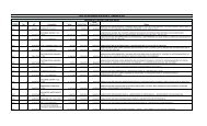
Table 7. The DMR classification of the right abutment.<br />
Situation<br />
Type of discontinuity<br />
CF<br />
R STA<br />
RMR BD<br />
DMR STA<br />
Table 8. The DMR classification of the left abutment..<br />
Situation<br />
Type of discontinuity<br />
CF<br />
R STA<br />
RMR BD<br />
DMR STA<br />
Bedding<br />
1.7×10 -2<br />
-15<br />
Bedding<br />
5.48×10 -4<br />
-15<br />
Degree of safety<br />
No primary concern<br />
Concern<br />
Serious concern<br />
J 1<br />
0.34<br />
J 1<br />
-7<br />
1.64<br />
-7<br />
Mehdi Torabi Kaveh and Mojtaba Heidari<br />
Area 1<br />
55.70<br />
Area 1<br />
68.40<br />
J 2<br />
0.16<br />
-7<br />
J 2<br />
(2)<br />
(3)<br />
1.84<br />
-7<br />
graphic projection technique. Kinematic analysis was used for the study<br />
area to estimate the MSSA regarding the three basic failure mo<strong>de</strong>s: plane<br />
sliding, wedge sliding and toppling.<br />
The aforementioned kinematic analysis was performed for left abutment<br />
slopes (area 2) at the dam site using dominant discontinuity sets.<br />
Kinematic analysis (Table 9 and Figure 4) results indicated that joint<br />
inclination was the most important parameter affecting rock mass instability.<br />
The analysis revealed possible wedge, planar and toppling failures in<br />
the left abutment (area 2).<br />
Conclusions<br />
The concrete Chamshir dam will be located on the limestone and<br />
marl rocks of the Mishan formation. Good rock mass quality was indicated<br />
for these rocks; however, according to DMR and kinematic analysis,<br />
most parts of the dam foundation (except the left abutment, area 2) were<br />
safe, being rated low-risk in terms of instability occurrence and magnitu<strong>de</strong>.<br />
It is therefore recommen<strong>de</strong>d that slope failure should be constantly<br />
monitored.<br />
Despite RQD and RMR values showing favourable condition for the<br />
dam abutments, the DMR classification provi<strong>de</strong>d more accurate assessment<br />
and was more reliable, i.e. consi<strong>de</strong>rable correlation between such<br />
classification and the kinematic analysis.<br />
Acknowledgments<br />
The study was financed by the Mahab Ghodss Consulting Engineering<br />
Company. The authors are grateful to Dr. Hamid Reza Zarei for supplying<br />
the authors with the dam site’s practical test data and Mr. Jason<br />
Garry for editing the paper in English and Mr. Mirmohammad Miri for<br />
translating it.<br />
References<br />
Aksoy, H. and Ercanoglu, M. (2007). Fuzzified kinematic analysis of discontinuity-controlled<br />
rock slope instabilities, Eng Geol. 89, 209–19.<br />
Fault set<br />
0.43<br />
-7<br />
Right abutment<br />
Fault set<br />
1.84<br />
-7<br />
84<br />
Bedding<br />
3.9×10 -4<br />
-15<br />
Left abutment<br />
Bedding<br />
2.22<br />
-15<br />
84<br />
J 1<br />
3.07<br />
-7<br />
J1 8.82×10⁻⁴ -7<br />
Area 2<br />
78.02<br />
Area 2<br />
J 2<br />
0.16<br />
-7<br />
0.00<br />
J 2<br />
0.43<br />
-7<br />
Fault set 1<br />
2.38<br />
-7<br />
Fault set<br />
0.43<br />
-7<br />
Fault set 2<br />
1.84<br />
-7
An engineering geological appraisal of the Chamshir dam foundation using DMR classification and kinematic analysis, southwest of Iran 135<br />
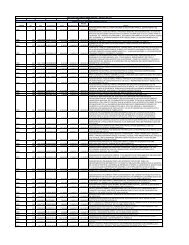
Table 9. Kinematic analysis regarding sliding in the left abutment (area 2).<br />
Sliding along joint<br />
sets<br />
1-2<br />
1-3<br />
1-4<br />
1-5<br />
2-3<br />
2-4<br />
2-5<br />
3-4<br />
3-5<br />
4-5<br />
Slope face dip<br />
direction<br />
340.0<br />
340.0<br />
340.0<br />
340.0<br />
340.0<br />
Wedge sliding results<br />
Slope face dip<br />
direction<br />
340.0<br />
340.0<br />
340.0<br />
340.0<br />
340.0<br />
340.0<br />
340.0<br />
340.0<br />
340.0<br />
340.0<br />
Planar failure<br />
Failure along joint<br />
set<br />
1<br />
2<br />
3<br />
4<br />
5<br />
Maximum safe<br />
angle<br />
90<br />
90<br />
90<br />
90<br />
90<br />
76*<br />
68**<br />
90<br />
90<br />
90<br />
Maximum safe<br />
angle (<strong>de</strong>g.)<br />
90<br />
76***<br />
90<br />
90<br />
90<br />
Figure 4. Kinematic conditions for the left abutment (area 2),<br />
1: bedding, 2: J1, 3: J2, 4: fault set Ι, 5: fault set Π, 6: slope face<br />
Inters. line<br />
1-2<br />
1-3<br />
1-4<br />
1-5<br />
2-3<br />
2-4<br />
2-5<br />
3-4<br />
3-5<br />
4-5<br />
Slope face dip<br />
direction<br />
340.0<br />
340.0<br />
340.0<br />
340.0<br />
340.0<br />
Orientation of intersection lines<br />
Trend (<strong>de</strong>g.)<br />
55.8<br />
58.1<br />
29.0<br />
28.6<br />
57.0<br />
322.8<br />
39.6<br />
223.0<br />
168.8<br />
28.8<br />
Toppling failure<br />
Failure along joint<br />
set<br />
1<br />
2<br />
3<br />
4<br />
5<br />
Plunge (<strong>de</strong>g.)<br />
8.8<br />
9.1<br />
4.2<br />
4.1<br />
4.2<br />
75.9<br />
51.7<br />
44.3<br />
75.9<br />
5.1<br />
Maximum safe<br />
angle (<strong>de</strong>g.)<br />
90<br />
90<br />
53****<br />
90<br />
90<br />
* Potential wedge failures along the intersection lines for joint set (1) with fault set 1 were possible if slope angle excee<strong>de</strong>d 76 <strong>de</strong>grees. ** Potential wedge failures along<br />
the intersection lines for joint set (1) with fault set 2 were possible if slope angle excee<strong>de</strong>d 68 <strong>de</strong>grees. *** Potential planar failure along faults was possible if slope angle<br />
excee<strong>de</strong>d 76 <strong>de</strong>gree. **** Potential toppling failure due to the orientation of joint set 2 was possible if slope angle excee<strong>de</strong>d 53 <strong>de</strong>grees. Analysis must be carried out for<br />
faults sited close to the slope face in the vicinity of such faults.
136<br />
Berberian, M. (1995). Master “blind” thrust faults hid<strong>de</strong>n un<strong>de</strong>r the Zagros<br />
folds: active basement tectonics and surface morphotectonics,<br />
Tectonophysics. 241, 193-224.<br />
Bianewski, Z. T. (1989). Engineering Rock Mass Classification, Wiley,<br />
Chichester, 251 pp.<br />
Deere, D. U. (1964). Technical <strong>de</strong>scription of cores for engineering purposes,<br />
Rock. Mech. Eng. Geol. 1, 17- 22.<br />
Di Salvo, C. A. (1982). Geomechanics classification of the rock mass at<br />
Segunda Angostura Dam, 14th ICOLD, Rio <strong>de</strong> Janeiro, Q53 R30.<br />
Gharouni-Nik, M. (2008). Comparison of the results of FDT and PLT in<br />
<strong>de</strong>termining <strong>de</strong>formability modulus of the rock mass in the Chamshir<br />
dam site in Iran, The 3 rd International Conference on Site Characterization,<br />
Taipei, Taiwan, 1-4 April.<br />
Goodman, R. E. (1976). Methods of geological engineering in discontinuous<br />
rocks, San Francisco, West Publishing.<br />
Goodman, R. E. (1989). Introduction to rock mechanics, 2 nd ed. New<br />
York, Wiley.<br />
Goodman, R. E. and Shi, G. H. (1985). Block theory and its application<br />
to rock engineering, New Jersey, Prentice-Hall.<br />
Hemmen. (2002). Paris dam, internet site for DMR dams foundations,<br />
http:// www.stmr.es.<br />
Hoek, E., Carranza-Torres, E. and Corkum, B. (2002). Hoek-Brown failure<br />
criterium-2002 edition, NARMS, Toronto.<br />
http://www.google.com/earth/in<strong>de</strong>x.html<br />
Ichikawa, K. (1999). Geological investigation of dams, Proc. of 2 nd Asian<br />
Symposium on Engineering Geology and the Environment, Malaysian<br />
National Group, Bangi, Malaysia, 1-44–1-57.<br />
ISRM. (1981). Rock characterization, testing and monitoring, In: Brown,<br />
E.T. (Ed.), ISRM Suggested Methods, Pergamon Press, Oxford, 211pp.<br />
Kliche, C. A. (1999). Rock Slope Stability SME, Littleton, CO.<br />
Kulatilake, P. H. S. W., Wang, L., Tang, H. and Liang, Y. (2011). Evaluation<br />
of rock slope stability for Yujian River dam site by kinematic and<br />
block theory analyses, Computers and Geotechnics. 38, 846–860.<br />
Mehdi Torabi Kaveh and Mojtaba Heidari<br />
Marcello, A., Eusepi G., Olivero, S. and Di Bacco, R. (1991). Ravanasella<br />
dam on difficult foundation, 17th ICOLD, Vienna, Q 66 R 21.<br />
Markland, J. T. (1972). A useful technique for estimating the stability of<br />
rock slopes when the rigid wedge sliding type of failure is expected,<br />
Imp, Coll, Rock Mech, Res, Rep, 19, 10.<br />
Matherson, G. D. (1988). The collection and use of field discontinuity<br />
data in rock slope <strong>de</strong>sign, Q J Eng Geol. 22, 19–30.<br />
Özsan, A. and Akin, M. (2002). Engineering geological assessment of the<br />
proposed Urus dam, Turkey, Eng Geol. 66, 271–81.<br />
Ramamurthy, T. (2004). A geo-engineering classification for rocks and<br />
rock masses, International Journal of Rock Mechanics & Mining Sciences.<br />
41, 89–101.<br />
Romana, M. (2003a). DMR (Dam Mass Rating). An adaptation of RMR<br />
geomechanics classification for use in dams foundations, Int. Cong.<br />
On Rock Mechanics, (Technology roadmap for rock mechanics)<br />
South African Inst, Of Min, and Meta, 977-980.<br />
Romana, M. (2004). DMR (an adaptation of RMR), a new geomechanics<br />
classification for use in dams foundations, 9 th Congresso Luso <strong>de</strong><br />
Geotecnia, Aveiro, 12pp.<br />
Setu<strong>de</strong>hnia, A. and OB-Perry, G. T. (1966). Geological map of Gachsaran,<br />
Iranian Oil Operating Companies (IOOC), 1,100,000.<br />
Stocklin, J. (1968). Structural history and tectonics of Iran: a review,<br />
AAPG Bull. 52, 1229-1258.<br />
Tehran Sahab and Parab Fars Consulting Engineering Companies. (1997).<br />
Engineering geology report concerning the Chamshir dam site (in<br />
Persian), Chamshir Dam project, Teheran, Iran.<br />
Torabi-Kaveh, M., Heidari, M., Zarei, H. R. and Ghiasi, M. B. (2010).<br />
Engineering geological investigation of the foundation of the Chamshir<br />
dam site by use of DMR classification (Iran), 7 th International<br />
symposium on eastern Mediterranean geology, University of Çukurova,<br />
Adana, Turkey, 18‐22 October.<br />
Van Schalkwyk. (1982). Geology and selection of the type of dam in<br />
South Africa, 14 th ICOLD, Río <strong>de</strong> Janeiro, Q51. R44.