30. Engineering Design Guidelines For Furnaces - KLM Technology ...
30. Engineering Design Guidelines For Furnaces - KLM Technology ...
30. Engineering Design Guidelines For Furnaces - KLM Technology ...
- No tags were found...

Create successful ePaper yourself
Turn your PDF publications into a flip-book with our unique Google optimized e-Paper software.
<strong>KLM</strong> <strong>Technology</strong>GroupPage : 1 of 80Rev: 02Practical <strong>Engineering</strong><strong>Guidelines</strong> for ProcessingPlant Solutionswww.klmtechgroup.comMay 2010<strong>KLM</strong> <strong>Technology</strong> Group#03-12 Block Aronia,Jalan Sri Perkasa 2Taman Tampoi Utama81200 Johor BahruFURNACE(ENGINEERING DESIGN GUIDELINE)Co AuthorsRev 1 Maidafitri Dewi PriatiRev 2 Aprilia JayaKarl Kolmetz<strong>KLM</strong> <strong>Technology</strong> Group is providing the introduction to this guideline for free onthe internet. Please go to our website to order the complete document.www.klmtechgroup.comTABLE OF CONTENTINTRODUCTION 4Scope 4General <strong>Design</strong> Consideration 8DEFINITION 17NOMENCLATURE 20THEORY OF THE DESIGN 22A. Burner 22B. Radiant Section 27C. Decoking of fire heater tubes 39D. Convection Section 41
<strong>KLM</strong> <strong>Technology</strong>GroupPractical <strong>Engineering</strong><strong>Guidelines</strong> for Processing PlantSolutionsFURNACE(ENGINEERING DESIGN GUIDELINES)Page 2 of 80Rev: 02May 2012E. Stack 47F. Auxiliary Equipment 52G. Efficiency of Furnace 61APPLICATION 68Application 1: <strong>Design</strong> of furnace with fuel oil 62Application 2: <strong>Design</strong> of furnace with fuel gas 69REFEREENCE 76CALCULATION SPREADSHEET<strong>Design</strong> of Furnace with Fuel Oil.xls 77<strong>Design</strong> of Furnace with Fuel Gas.xls 78LIST OF TABLETable 1: The use of fuel at the burner 25Table 2: Burner capacity 25Table 3: Common Heater Tube Sizes and Properties 29Table 4: <strong>Design</strong> Conditions for Process Heaters 34Table 5: Thick fins and studs are typically used in the convection section 43Table 6: Minimum pipe spacing for convection section tubes 44Table 7: Minimum tube spacing for convection section tubes 44Table 8: Rotary Sootblower: for Max. Element Length of 10 in 56These design guideline are believed to be as accurate as possible, but are very general and not for specific designcases. They were designed for engineers to do preliminary designs and process specification sheets. The finaldesign must always be guaranteed for the service selected by the manufacturing vendor, but these guidelines willgreatly reduce the amount of up front engineering hours that are required to develop the final design. The guidelinesare a training tool for young engineers or a resource for engineers with experience.This document is entrusted to the recipient personally, but the copyright remains with us. It must not be copied,reproduced or in any way communicated or made accessible to third parties without our written consent.
<strong>KLM</strong> <strong>Technology</strong>GroupPractical <strong>Engineering</strong><strong>Guidelines</strong> for Processing PlantSolutionsFURNACE(ENGINEERING DESIGN GUIDELINES)Page 3 of 80Rev: 02May 2012Table 9: Rotary Sootblower: for Max. Element Length of 20 in 57LIST OF FIGUREFigure 1: Vertical cylindrical fired heater: (a) all radiant, and (b) helical coil 6Figure 2: Horizontal tube cabin fired heaters: (a) cabin with convection section and(b) cabin with dividing bridge wall 7Figure 3: Hoop-tube fired heater 8Figure 4: Vertical tube box fired heaters 10Figure 5: Horizontal tube box fired heaters 11Figure 6: Multiple cell heaters 12Figure 7: Helical coil fired heater 13Figure 8: Typical natural draft burner (combination gas/liquid burner) 23Figure 9: Typical Axial-Flow Burner <strong>For</strong>ced Draft Combination Gas/Oil Burner 24Figure 10: Decoking on the fired heater tubes 40Figure 11: Damper 50Figure 12: Square Pitch Finned Tubes : Longitudinal Arrangement 54Figure 13:. Triangular Pitch Finned Tubes : Longitudinal Arrangement 54Figure 14: Square Pitch Finned Tubes : Perpendicular Arrangement 55Figure 15: Triangular Pitch Finned Tubes : Perpendicular Arrangement 55Figure 16: Fans and Blower: (a) Natural Draft, (b) <strong>For</strong>ced Draft, (c) Induced Draft and(d) Balance Draft 59Figure 17: Air Preheater 60These design guideline are believed to be as accurate as possible, but are very general and not for specific designcases. They were designed for engineers to do preliminary designs and process specification sheets. The finaldesign must always be guaranteed for the service selected by the manufacturing vendor, but these guidelines willgreatly reduce the amount of up front engineering hours that are required to develop the final design. The guidelinesare a training tool for young engineers or a resource for engineers with experience.This document is entrusted to the recipient personally, but the copyright remains with us. It must not be copied,reproduced or in any way communicated or made accessible to third parties without our written consent.
<strong>KLM</strong> <strong>Technology</strong>GroupPractical <strong>Engineering</strong><strong>Guidelines</strong> for Processing PlantSolutionsFURNACE(ENGINEERING DESIGN GUIDELINES)Page 4 of 80Rev: 02May 2012<strong>KLM</strong> <strong>Technology</strong> Group is providing the introduction to this guideline for free onthe internet. Please go to our website to order the complete document.INTRODUCTIONScopewww.klmtechgroup.comThis guideline provides knowledge on how to design a furnace. This design guideline canassist to understand the basic design of furnace with suitable size, material and heat ofcombustion. A furnace is one of the most important pieces of equipment in a processplant. Furnace firing provides a large part of the heat for the process. The heat for theprocess comes from the combustion of fuels.The choice of furnace style and design is crucial for the best performance of furnace.Factors affecting the performance of furnace are influenced by the maximum the heatabsorbed, the capacity of burners, process requirements, economics and safety.The theory section explains the selection of the furnace type, calculation of sizing, heattransfer concepts and combustion basics. The application of the furnace theory with theexamples assists the user to study the furnace concepts and be prepared to perform theactual design of the furnace.These design guideline are believed to be as accurate as possible, but are very general and not for specific designcases. They were designed for engineers to do preliminary designs and process specification sheets. The finaldesign must always be guaranteed for the service selected by the manufacturing vendor, but these guidelines willgreatly reduce the amount of up front engineering hours that are required to develop the final design. The guidelinesare a training tool for young engineers or a resource for engineers with experience.This document is entrusted to the recipient personally, but the copyright remains with us. It must not be copied,reproduced or in any way communicated or made accessible to third parties without our written consent.
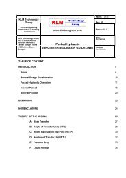
<strong>KLM</strong> <strong>Technology</strong>GroupPractical <strong>Engineering</strong><strong>Guidelines</strong> for Processing PlantSolutionsFURNACE(ENGINEERING DESIGN GUIDELINES)Page 5 of 80Rev: 02May 2012General <strong>Design</strong> ConsiderationHeat is one of most important things in the process plant industry. Equipment thatproduces and supplies the heat requirement to process plant is called a furnace.<strong>Furnaces</strong> have high temperatures, open flames, oxygen and fuel; all the components ofcombustion.The term furnace can also refer to a direct fired heater. They expose hydrocarbon streamto heat that drives a distillation tower, a reactor, and in some cases, change the stream'smolecular structure through cracking.Basically furnace has four basic components, consisting of box, burner, coil, and stack.The burner will produce the heat then the heat liberated by the combustion of fuel istransfer to a process fluid flowing through tubular coils. In this below are several types offurnace:1. Vertical cylindrical fired heaterThis furnace is commonly used in hot oil service and other processes where the dutiesare usually small. These heaters are probably the most common in use today and areused for heat duties up to about 150 MBtu/hr. This type of cylindrical upright, tube inthe radiant section mounted vertically in a circle round of the burner. The burner islocated on the bottom floor, so that the flame is parallel with the tube. Fire heater ofthis type can be design without or with convection section. Below is kinds of the crosssection of vertical-cylindrical fired heater.a. Vertical cylindrical all radiant:The all-radiant heater is inexpensive, but since the temperature of flue gasesleaving the heater is high, 1500 – 1800oF . Heater of this type does not haveconvection section. Usually this type have low efficiency and heat duty rangesfrom 3-7 million kcal/hour.b. Vertical cylindrical helical coil:The coil is arranged helically along the cylindrical wall of the combustionchamber. Its primary use is to heat thermal fluids and natural gas. Capacitiesrange from 1 to 30 million Btu/hour.These design guideline are believed to be as accurate as possible, but are very general and not for specific designcases. They were designed for engineers to do preliminary designs and process specification sheets. The finaldesign must always be guaranteed for the service selected by the manufacturing vendor, but these guidelines willgreatly reduce the amount of up front engineering hours that are required to develop the final design. The guidelinesare a training tool for young engineers or a resource for engineers with experience.This document is entrusted to the recipient personally, but the copyright remains with us. It must not be copied,reproduced or in any way communicated or made accessible to third parties without our written consent.
<strong>KLM</strong> <strong>Technology</strong>GroupPractical <strong>Engineering</strong><strong>Guidelines</strong> for Processing PlantSolutionsFURNACE(ENGINEERING DESIGN GUIDELINES)Page 6 of 80Rev: 02May 2012c. Vertical cylindrical with crossflow convection section:The convection section is installed above the combustion chamber. Mostly, airpreheater are added to increase the efficiency. Heat duty of this type from 5-35million kcal/hour.d. Vertical cylindrical with integral convection:The distinguishing feature of this type is the use of added surface area on theupper part of the radiant coil to promote convection heating. This type is addedsurface area on the upper part of the radiant coil to promote convection heating.Duties are from 2.5 – 25 million kcal /hr.Convection coilConvection coilRadiantcoilRadiantcoilBurnerBurner(a)(b)Figure 1: Vertical cylindrical fired heater: (a) all radiant and (b) helical coilThese design guideline are believed to be as accurate as possible, but are very general and not for specific designcases. They were designed for engineers to do preliminary designs and process specification sheets. The finaldesign must always be guaranteed for the service selected by the manufacturing vendor, but these guidelines willgreatly reduce the amount of up front engineering hours that are required to develop the final design. The guidelinesare a training tool for young engineers or a resource for engineers with experience.This document is entrusted to the recipient personally, but the copyright remains with us. It must not be copied,reproduced or in any way communicated or made accessible to third parties without our written consent.
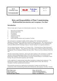
<strong>KLM</strong> <strong>Technology</strong>GroupPractical <strong>Engineering</strong><strong>Guidelines</strong> for Processing PlantSolutionsFURNACE(ENGINEERING DESIGN GUIDELINES)Page 7 of 80Rev: 02May 20122. Horizontal tube cabin fired heatersThis cabin has room type consists of the radiation and convection. Tube-tube mountedhorizontally while the burner is located on the floor furnace, so that the flame is notstraight and parallel to the wall heater. The first layer of tubes in the convectionsection directly facing into combustion chamber or the radiant fire box called shieldtubes. The burner mounted on the floor of the cabin and fire is directed vertically.Cabin fired heater have some variation in the application. It is like cabin furnace with acentre wall. In the figure below the fire heater usually can be used for the large firedheater and has two separate heating zones are required in the radiant section. Thisdesign is economical, high efficiency duties are from 20 - 50 million kcal/hour. In manyoperations, about 75% of the heat is absorbed in the radiant zone of a fired heater.These design guideline are believed to be as accurate as possible, but are very general and not for specific designcases. They were designed for engineers to do preliminary designs and process specification sheets. The finaldesign must always be guaranteed for the service selected by the manufacturing vendor, but these guidelines willgreatly reduce the amount of up front engineering hours that are required to develop the final design. The guidelinesare a training tool for young engineers or a resource for engineers with experience.This document is entrusted to the recipient personally, but the copyright remains with us. It must not be copied,reproduced or in any way communicated or made accessible to third parties without our written consent.
<strong>KLM</strong> <strong>Technology</strong>GroupPractical <strong>Engineering</strong><strong>Guidelines</strong> for Processing PlantSolutionsFURNACE(ENGINEERING DESIGN GUIDELINES)Page 8 of 80Rev: 02May 2012Convection coilConvection coilRadiantcoilRadiantcoilBurnerBurner(a)(b)Figure 2: Horizontal tube cabin fired heaters: (a) cabin with convection section and (b)cabin with dividing bridge wallThese design guideline are believed to be as accurate as possible, but are very general and not for specific designcases. They were designed for engineers to do preliminary designs and process specification sheets. The finaldesign must always be guaranteed for the service selected by the manufacturing vendor, but these guidelines willgreatly reduce the amount of up front engineering hours that are required to develop the final design. The guidelinesare a training tool for young engineers or a resource for engineers with experience.This document is entrusted to the recipient personally, but the copyright remains with us. It must not be copied,reproduced or in any way communicated or made accessible to third parties without our written consent.
<strong>KLM</strong> <strong>Technology</strong>GroupPractical <strong>Engineering</strong><strong>Guidelines</strong> for Processing PlantSolutionsFURNACE(ENGINEERING DESIGN GUIDELINES)Page 9 of 80Rev: 02May 20123. Hoop-tube fired heaterThis fire heater has tube bent like U-type with vertically oriented. In all-vapor flow,non-coking services where low coil pressure drop is desired. This design is usedwhere the pressure drop must be very low since the path through each tube providesa design with many passes. Application of this type is in the catalytic reformerscharge heater. Duties are from 13-25 million kcal/hr.Convection coilRadiantcoilBurnerTerminal monitorsFigure 3:. Hoop-tube fired heaterThese design guideline are believed to be as accurate as possible, but are very general and not for specific designcases. They were designed for engineers to do preliminary designs and process specification sheets. The finaldesign must always be guaranteed for the service selected by the manufacturing vendor, but these guidelines willgreatly reduce the amount of up front engineering hours that are required to develop the final design. The guidelinesare a training tool for young engineers or a resource for engineers with experience.This document is entrusted to the recipient personally, but the copyright remains with us. It must not be copied,reproduced or in any way communicated or made accessible to third parties without our written consent.
<strong>KLM</strong> <strong>Technology</strong>GroupPractical <strong>Engineering</strong><strong>Guidelines</strong> for Processing PlantSolutionsFURNACE(ENGINEERING DESIGN GUIDELINES)Page 10 of 80Rev: 02May 20124. Vertical tube box fired heatersIn this fire heater, tubes stand vertically along wall in the radiant section. Verticalradiant tubes are arranged in a single row in each combustion cell (there are oftentwo cells) and are fired from both sides of the row. Such an arrangement yields auniform distribution of heat-transfer rates about the tube circumference. This heater issuitable for the large forced-draft burners. Requirement of heat input to each cellprovided by burner.5. Horizontal tube box fired heatersThe radiant and convection section in a typical of horizontal tube box in the Figure 5are separate by a wall called bridge wall. Function of bridge wall is to create a gooddirection of flame and to stream the smoke in to flue stack. Burners are firing from thefloor along both sides of the bridge wall. Duties are from 30 to 8 million kcal /hour.6. Multiple cell heaters<strong>For</strong> two-cell horizontal tube box have high efficiency, duties from 25-65 millionkcal/hour.7. Helical coil fired heaterThis heater configuration is commonly used where the duties are small. Since eachpass consists of a separate winding of the coil, pressure drop options are limited.Many of these only have a radiant section, since efficiency is often not that critical,especially in intermittent services like for a regeneration heater.These design guideline are believed to be as accurate as possible, but are very general and not for specific designcases. They were designed for engineers to do preliminary designs and process specification sheets. The finaldesign must always be guaranteed for the service selected by the manufacturing vendor, but these guidelines willgreatly reduce the amount of up front engineering hours that are required to develop the final design. The guidelinesare a training tool for young engineers or a resource for engineers with experience.This document is entrusted to the recipient personally, but the copyright remains with us. It must not be copied,reproduced or in any way communicated or made accessible to third parties without our written consent.
<strong>KLM</strong> <strong>Technology</strong>GroupPractical <strong>Engineering</strong><strong>Guidelines</strong> for Processing PlantSolutionsFURNACE(ENGINEERING DESIGN GUIDELINES)Page 11 of 80Rev: 02May 2012To Stack1 side fired walltubes2 side fired centertubesBurners<strong>For</strong>ced airsupply directFigure 4: Vertical tube box fired heatersThese design guideline are believed to be as accurate as possible, but are very general and not for specific designcases. They were designed for engineers to do preliminary designs and process specification sheets. The finaldesign must always be guaranteed for the service selected by the manufacturing vendor, but these guidelines willgreatly reduce the amount of up front engineering hours that are required to develop the final design. The guidelinesare a training tool for young engineers or a resource for engineers with experience.This document is entrusted to the recipient personally, but the copyright remains with us. It must not be copied,reproduced or in any way communicated or made accessible to third parties without our written consent.
<strong>KLM</strong> <strong>Technology</strong>GroupPractical <strong>Engineering</strong><strong>Guidelines</strong> for Processing PlantSolutionsFURNACE(ENGINEERING DESIGN GUIDELINES)Page 12 of 80Rev: 02May 2012StackRefractory liningHeader boxProcess inExtendedsurfaceBreechingReturn Tubebend sheetCrossArchover Bridge wallHeaderboxObservationboxShieldsectionConvectionsectionRefractoryliningTubesupportRadiant sectionPlatformProcess outAccessdoorBurnerPierFigure 5: Horizontal tube box fired heatersThese design guideline are believed to be as accurate as possible, but are very general and not for specific designcases. They were designed for engineers to do preliminary designs and process specification sheets. The finaldesign must always be guaranteed for the service selected by the manufacturing vendor, but these guidelines willgreatly reduce the amount of up front engineering hours that are required to develop the final design. The guidelinesare a training tool for young engineers or a resource for engineers with experience.This document is entrusted to the recipient personally, but the copyright remains with us. It must not be copied,reproduced or in any way communicated or made accessible to third parties without our written consent.
<strong>KLM</strong> <strong>Technology</strong>GroupPractical <strong>Engineering</strong><strong>Guidelines</strong> for Processing PlantSolutionsFURNACE(ENGINEERING DESIGN GUIDELINES)Page 13 of 80Rev: 02May 2012Convection coilRadiantcoilBurnerBurnerFigure 6: Multiple cell heatersThese design guideline are believed to be as accurate as possible, but are very general and not for specific designcases. They were designed for engineers to do preliminary designs and process specification sheets. The finaldesign must always be guaranteed for the service selected by the manufacturing vendor, but these guidelines willgreatly reduce the amount of up front engineering hours that are required to develop the final design. The guidelinesare a training tool for young engineers or a resource for engineers with experience.This document is entrusted to the recipient personally, but the copyright remains with us. It must not be copied,reproduced or in any way communicated or made accessible to third parties without our written consent.
<strong>KLM</strong> <strong>Technology</strong>GroupPractical <strong>Engineering</strong><strong>Guidelines</strong> for Processing PlantSolutionsFURNACE(ENGINEERING DESIGN GUIDELINES)Page 14 of 80Rev: 02May 2012Figure 7: Helical coil fired heaterThese design guideline are believed to be as accurate as possible, but are very general and not for specific designcases. They were designed for engineers to do preliminary designs and process specification sheets. The finaldesign must always be guaranteed for the service selected by the manufacturing vendor, but these guidelines willgreatly reduce the amount of up front engineering hours that are required to develop the final design. The guidelinesare a training tool for young engineers or a resource for engineers with experience.This document is entrusted to the recipient personally, but the copyright remains with us. It must not be copied,reproduced or in any way communicated or made accessible to third parties without our written consent.
<strong>KLM</strong> <strong>Technology</strong>GroupPractical <strong>Engineering</strong><strong>Guidelines</strong> for Processing PlantSolutionsFURNACE(ENGINEERING DESIGN GUIDELINES)Page 15 of 80Rev: 02May 2012A Fired heater will work well if designed properly. The design requirements must beproperly addressed. Fired heater performance can be measured by a combination ofoperability and maintenance.There are several factors effecting fired heater selection and design: all-liquid vaporizingservice and all-vapor service.1. Fire heaters in all-liquid or vaporizing serviceInside the tube wall coke may be formed that can interfere with heat transfer process.Fired heaters should be design to minimize coke. Incipient coke begins to form at afilm temperature above about 660oF, usually equivalent to a bulk fluid temperature ofabout 600oF. In other services such as visbreaking and thermal cracking, where fluidcracking is an inherent characteristic of the process, acceptable coke formation andrun length can usually be attained if film temperatures do not exceed 910 o Fequivalent to a bulk fluid temperature of about 880 o F.<strong>For</strong> reduce the formation of coke, a high inside film coefficient is necessary tominimize the difference between bulk fluid and film temperature. The higher thespeed of the mass of the heat transfer coefficient will be better. Therefore, the massof turbulent flow must be maintaining in the tube.2. Fire heater in all-vapor service<strong>For</strong> this fired heater service is generally not as susceptible to the severe cokingproblems as those in vaporizing services because of the lighter nature of the processfluid.These design guideline are believed to be as accurate as possible, but are very general and not for specific designcases. They were designed for engineers to do preliminary designs and process specification sheets. The finaldesign must always be guaranteed for the service selected by the manufacturing vendor, but these guidelines willgreatly reduce the amount of up front engineering hours that are required to develop the final design. The guidelinesare a training tool for young engineers or a resource for engineers with experience.This document is entrusted to the recipient personally, but the copyright remains with us. It must not be copied,reproduced or in any way communicated or made accessible to third parties without our written consent.
<strong>KLM</strong> <strong>Technology</strong>GroupPractical <strong>Engineering</strong><strong>Guidelines</strong> for Processing PlantSolutionsFURNACE(ENGINEERING DESIGN GUIDELINES)Page 16 of 80Rev: 02May 2012To achieve the lowest possible utility cost, a furnace must operate at maximum efficiency.When a furnace is operated properly, the furnace and its parts have a longer working lifewith minimum repairs. A properly run furnace is a safe furnace. Skillful handing of afurnace means safety for worker.Heat is produce by the ignition of fuel at the burner in the firebox. The tubes along thewall of the firebox are the radiant and the shock bank tubes. These tubes receive radiantheat from the burners. The firebox wall and roof is lined with a material then reduce heatlosses and radiates heat back to the tubes. The entire furnace structure must be air tightfor efficient furnace operation. Air should only enter at designed entries. An air leakreduces the efficiency of the furnace. Below are design considerations for furnace.1. Heaters shall be designed for uniform heat distribution2. Multi-pass heaters shall be designed for hydraulic and thermal symmetry of allpasses. The number of passes shall be minimized. Each pass shall be a singlecircuit3. Average heat flux density in the radiant section is normally based on single row oftubes with two nominal tube diameter spacing.4. The maximum allowable inside film temperature for any process service shall not beexceeded in the radiant, shield, or convection sections.5. minimum radiation loss 2.5 % the total heat input6. Natural draft needs 25% excess air when oil is the primary fuel and 20 % excess airwhen fuel gas is the primary fuel. In case of forced draft operation, 20% Excess airfor fuel oil and 15% Excess air for fuel gas7. Heaters shall be designed such that a negative pressure of at least 0.10 inches ofwater (0.025 kilopascals) is maintained in the radiant and convection sections atmaximum heat release with design excess air.8. The flue gas dew point can be predicted, and the minimum tube-metal temperaturecan be kept high enough to prevent condensation, if the fuel's sulfur content hasbeen correctly stated. (<strong>For</strong> estimated flue gas dew points with respect to sulfurcontent in fuel oil and gas9. In a well-design heater, the radiant-section heat duty should represent more than60% to 70% of the total heat duty10. The bridge wall temperature should range between 800°C to 1,000°C.These design guideline are believed to be as accurate as possible, but are very general and not for specific designcases. They were designed for engineers to do preliminary designs and process specification sheets. The finaldesign must always be guaranteed for the service selected by the manufacturing vendor, but these guidelines willgreatly reduce the amount of up front engineering hours that are required to develop the final design. The guidelinesare a training tool for young engineers or a resource for engineers with experience.This document is entrusted to the recipient personally, but the copyright remains with us. It must not be copied,reproduced or in any way communicated or made accessible to third parties without our written consent.
<strong>KLM</strong> <strong>Technology</strong>GroupPractical <strong>Engineering</strong><strong>Guidelines</strong> for Processing PlantSolutionsFURNACE(ENGINEERING DESIGN GUIDELINES)Page 17 of 80Rev: 02May 201211. Higher radiant flux means less heat transfer surface area for a given heat duty;hence, a smaller furnace.12. The higher the film temperature, the greater is the tendency of the fluid (particularlya hydrocarbon) to crack and deposit a layer of coke.13. Heat-transfer fluids tend to degrade quickly at high film temperatures.14. The coke layer acts as an insulator, retarding heat transfer, which could cause tubeoverheating and lead to tube failure.15. Also, a heavy coke deposit can restrict the flow through the coil, lowering the insideheat transfer coefficient and further increasing the tube wall temperature.16. The smallest firebox for a certain duty will obviously produce the cheapest design.17. The flame impingement and consequent tube failure that could result can be avoidedby specifying a minimum safe distance between burners and tubes, based onexperienceFollowings are the mechanical design for furnace and these will be discussed a muchdeeper in theory section.1. Provision for thermal expansion shall take into consideration all specified operatingconditions, including short term conditions such as steam-air decoking.2. The convection section tube layout shall include space for future installation of sootblowersor steam lancing doors.3. The convection section shall incorporate space for future addition of two rows oftubes.4. When the heater is designed for fuel oil firing, soot-blowers shall be provided forconvection section cleaning.5. Vertical cylindrical heaters shall be designed with maximum height to diameter ratioof 2.75, where the height is the radiant section height and the tube circle diameter.6. Shield sections shall have at least three rows of bare tubes.7. Convection sections shall be designed to minimize flue gas bypass. Baffles may beemployed.8. The minimum clearance from grade to burner plenum or register shall be 6 feet 6inches (2.0 meters) for floor fired heaters.These design guideline are believed to be as accurate as possible, but are very general and not for specific designcases. They were designed for engineers to do preliminary designs and process specification sheets. The finaldesign must always be guaranteed for the service selected by the manufacturing vendor, but these guidelines willgreatly reduce the amount of up front engineering hours that are required to develop the final design. The guidelinesare a training tool for young engineers or a resource for engineers with experience.This document is entrusted to the recipient personally, but the copyright remains with us. It must not be copied,reproduced or in any way communicated or made accessible to third parties without our written consent.
<strong>KLM</strong> <strong>Technology</strong>GroupPractical <strong>Engineering</strong><strong>Guidelines</strong> for Processing PlantSolutionsFURNACE(ENGINEERING DESIGN GUIDELINES)Page 18 of 80Rev: 02May 20129. <strong>For</strong> vertical cylindrical heaters, the maximum radiant straight tube length shall be 60feet (18.3 meters).10. <strong>For</strong> horizontal heaters fired from both ends, the maximum radiation straight tubelength shall be 40 feet (12.2 meters).11. Radiant tubes shall be installed with minimum spacing from refractory or insulation totube centerline of one and one half nominal tube diameters, with a clearance of notless than 4 inches (10 centimeters) from the refractory or insulation.12. <strong>For</strong> horizontal radiant tubes, the minimum clearance from floor refractory to tubeoutside diameter shall be not less than 12 inches (30 centimeters).13. The heater arrangement shall allow for replacement of individual tubes withoutdisturbing adjacent tubes.DEFINITIONSAir Preheater - Heat exchanger device that uses some of the heat in the flue gases toraise the temperature of the air supply to the burners.Breeching - The hood that collects the flue gas at the convection section exit.Bridgewall Temperature - The temperature of the flue gas leaving the radiant sectionBulk Temperature - The average temperature of the process fluid at any tube crosssection.Center Wall - A refractory wall in the radiant section, which divides it into two separatecells.Coil - A series of straight tube lengths connected by 180 o return bends, forming acontinuous path through which the process fluid passes and is heated.Convection Section - The portion of a heater, consisting of a bank of tubes, whichreceives heat from the hot flue gases, mainly by convection.Corbelling - Narrow ledges extending from the convection section side walls to preventflue gas from flowing preferentially up the side of the convection section, between the walland the nearest tubes.These design guideline are believed to be as accurate as possible, but are very general and not for specific designcases. They were designed for engineers to do preliminary designs and process specification sheets. The finaldesign must always be guaranteed for the service selected by the manufacturing vendor, but these guidelines willgreatly reduce the amount of up front engineering hours that are required to develop the final design. The guidelinesare a training tool for young engineers or a resource for engineers with experience.This document is entrusted to the recipient personally, but the copyright remains with us. It must not be copied,reproduced or in any way communicated or made accessible to third parties without our written consent.
<strong>KLM</strong> <strong>Technology</strong>GroupPractical <strong>Engineering</strong><strong>Guidelines</strong> for Processing PlantSolutionsFURNACE(ENGINEERING DESIGN GUIDELINES)Page 19 of 80Rev: 02May 2012Crossover - Piping which transfers the process fluid either externally or internally fromone section of the heater to another.Damper - A device to regulate flow of gas through a stack or duct and to control draft in aheater.Draft - The negative pressure (vacuum) at a given point inside the heater, usuallyexpressed in inches of water.Excess Air - The percentage of air in the heater in excess of the stoichiometric amountrequired for combustion.Extended Surface - Surface added to the outside of bare tubes in the convection sectionto provide more heat transfer area.Film - A thin fluid layer adjacent to a pipe wall that remains in laminar flow, even when thebulk flow is turbulent.Film Temperature - The maximum temperature in the film, at the tube wall.Fire Box - A term used to describe the structure which surrounds the radiant coils andinto which the burners protrude.Flue Gas - A mixture of gaseous products resulting from combustion of the fuel.Fouling - The building up of a film of dirt, ash, soot or coke on heat transfer surfaces,resulting in increased resistance to heat flow.<strong>For</strong>ced Draft - Use of a fan to supply combustion air to the burners and to overcome thepressure drop through the burners.Fired Heater Efficiency - The ratio of heat absorbed to heat fired, on a lower heatingvalue basis.Header Box - The compartment at the end of the convection section where the headersare located.Heat Available - The heat absorbed from the products of combustion (flue gas) as theyare cooled from the flame temperature to a given flue gas temperature.These design guideline are believed to be as accurate as possible, but are very general and not for specific designcases. They were designed for engineers to do preliminary designs and process specification sheets. The finaldesign must always be guaranteed for the service selected by the manufacturing vendor, but these guidelines willgreatly reduce the amount of up front engineering hours that are required to develop the final design. The guidelinesare a training tool for young engineers or a resource for engineers with experience.This document is entrusted to the recipient personally, but the copyright remains with us. It must not be copied,reproduced or in any way communicated or made accessible to third parties without our written consent.
<strong>KLM</strong> <strong>Technology</strong>GroupPractical <strong>Engineering</strong><strong>Guidelines</strong> for Processing PlantSolutionsFURNACE(ENGINEERING DESIGN GUIDELINES)Page 20 of 80Rev: 02May 2012Heat Density - The rate of heat transfer per unit area to a tube, usually based on totaloutside surface area.Heat Duty - The total heat absorbed by the process fluid, usually expressed in MBtu/hrInduced Draft - Use of a fan to provide the additional draft required over that supplied bythe stack, to draw the flue gas through the convection section, and any downstream heatrecovery equipment.Lower Heating Value (LHV) - The theoretical heat of combustion of a fuel, when nocredit is taken for the heat of condensation of water in the flue gas.Mass Velocity - The mass flow rate per unit of flow area through the coil. Typical unitsare lb/s-sq. ft.Natural Draft - System in which the draft required to move combustion air into the heaterand flue gas through the heater and out the stack is provided by stack effect alone.Net Fuel - The fuel that would be required in the heater if there were no radiation losses.One-Side Fired Tubes - Radiant section tubes located adjacent to a heater wall haveonly one side directly exposed to a burner flame. Radiation to the back side of the tubesis by reflection/ re-radiation from the refractory wall.Pass - A coil that transports the process fluid from fired heater inlet to outlet.Radiant Section - The section of the fired heater in which heat is transferred to theheater tubes primarily by radiation from high-temperature flue gas.Service Factor – A measure of the continuity of operation, generally expressed as theratio of total running days for a given time period to the total calendar days in the period.Shield Section - The first two tube rows of the convection section.Sootblower - A steam lance (usually movable) in the convection section for blowing sootand ash from the tubes using high-pressure steam.These design guideline are believed to be as accurate as possible, but are very general and not for specific designcases. They were designed for engineers to do preliminary designs and process specification sheets. The finaldesign must always be guaranteed for the service selected by the manufacturing vendor, but these guidelines willgreatly reduce the amount of up front engineering hours that are required to develop the final design. The guidelinesare a training tool for young engineers or a resource for engineers with experience.This document is entrusted to the recipient personally, but the copyright remains with us. It must not be copied,reproduced or in any way communicated or made accessible to third parties without our written consent.
<strong>KLM</strong> <strong>Technology</strong>GroupPractical <strong>Engineering</strong><strong>Guidelines</strong> for Processing PlantSolutionsFURNACE(ENGINEERING DESIGN GUIDELINES)Page 21 of 80Rev: 02May 2012Stack - A cylindrical steel, concrete or brick shell which carries flue gas to theatmosphere and provides necessary draft.Stack Effect - The difference between the weight of a column of high-temperature gasesinside the heater and/or stack and the weight of an equivalent column of external air,usually expressed in inches of water per foot of height.Stack Temperature - The temperature of the flue gas as it leaves the convection section,or air preheater directly upstream of the stack.Two-Side Fired Tubes - Radiant section tubes which are exposed on both sides to directradiation from the burners.NOMENCLATURESA cp Cold plane area, (ft 2 )A shield Tube shield area, (ft 2 )A shield Tube shield area, (ft 2 )A w Refractory surface (ft 2 )A tube Area of tube, (ft 2 )A rl Right and left area (ft)A w Refractory surface (ft 2 )A r Radiant surface area (ft 2 )C Capacity design (btu/hr)E ff Efficiency of furnaceF Exchange factorG f Flue gas rate, (lb/hr)G Flue gas flow rate (lb/sec ft2)H Shell height (ft)H wall Wall height (ft)H persection Height per section (in)H CS Height of convection section (in)L Shell length (ft)L bm Mean beam length (ft)L bft The total length of bare of finned tubes, (ft)L exp Exposed length (ft)N burner The number of burnerNumber of tube in radiant section,N trThese design guideline are believed to be as accurate as possible, but are very general and not for specific designcases. They were designed for engineers to do preliminary designs and process specification sheets. The finaldesign must always be guaranteed for the service selected by the manufacturing vendor, but these guidelines willgreatly reduce the amount of up front engineering hours that are required to develop the final design. The guidelinesare a training tool for young engineers or a resource for engineers with experience.This document is entrusted to the recipient personally, but the copyright remains with us. It must not be copied,reproduced or in any way communicated or made accessible to third parties without our written consent.
<strong>KLM</strong> <strong>Technology</strong>GroupPractical <strong>Engineering</strong><strong>Guidelines</strong> for Processing PlantSolutionsFURNACE(ENGINEERING DESIGN GUIDELINES)Page 22 of 80Rev: 02May 2012N r Amount of radiant sectionN ts Number of tube in shield area,N tc Number of tube in ceiling area,N trl Number of tube in right and left area,N tchamber Number of tube in 1 chamber,N ts Number of tube in shield area,N tc Number of tube in ceiling area,N trl Number of tube in right and left area,N tchamber Number of tube in 1 chamber,N bsection Number of radiant burner per sectionN tr Number of tube in radiant sectionN t1 section Number of tube in 1 sectionOD Outside tube diameter (in)P Partial pressure of CO2 and H2O (atm)Q a Heat absorbed (btu/hr)Q rfc Radiant heat flux (btu/hr ft 2 )Q rac Radiant heat absorbed calculated (btu/hr)Q n Heat released (btu/lb)Q a Heat absorbed needed (btu/hr)Q ra Radiant heat absorption (btu/hr)Q rf Radiant heat flux (btu/hr ft 2 )Q conv Heat in convective zone, (btu/lb)Q rac Heat radiant absorbed calculated (lb/hr)T i Inlet process stream temperature ( o F)T o Outlet process stream temperature ( o F)T t Tube wall temperature ( o F)T LO Outlet temperature ( o F)T LI Inlet temperature ( o F)T S Stack temperature ( o F) T LIT SA Stack approach temperature ( o F)Uc Overall heat transfer coefficient (btu/hr ft 2 )V furnace Furnace volume (ft 3 )W Shell wide (ft)Xair Fraction excess airThese design guideline are believed to be as accurate as possible, but are very general and not for specific designcases. They were designed for engineers to do preliminary designs and process specification sheets. The finaldesign must always be guaranteed for the service selected by the manufacturing vendor, but these guidelines willgreatly reduce the amount of up front engineering hours that are required to develop the final design. The guidelinesare a training tool for young engineers or a resource for engineers with experience.This document is entrusted to the recipient personally, but the copyright remains with us. It must not be copied,reproduced or in any way communicated or made accessible to third parties without our written consent.
<strong>KLM</strong> <strong>Technology</strong>GroupPractical <strong>Engineering</strong><strong>Guidelines</strong> for Processing PlantSolutionsFURNACE(ENGINEERING DESIGN GUIDELINES)Page 23 of 80Rev: 02May 2012Greek LetersФ Gas emissivityαA r Effective absortivity (ft 2 )ρ Density (lb/ft 3 )SuperscriptMMass molecularThese design guideline are believed to be as accurate as possible, but are very general and not for specific designcases. They were designed for engineers to do preliminary designs and process specification sheets. The finaldesign must always be guaranteed for the service selected by the manufacturing vendor, but these guidelines willgreatly reduce the amount of up front engineering hours that are required to develop the final design. The guidelinesare a training tool for young engineers or a resource for engineers with experience.This document is entrusted to the recipient personally, but the copyright remains with us. It must not be copied,reproduced or in any way communicated or made accessible to third parties without our written consent.