Creating Objects exercise
Creating Objects exercise
Creating Objects exercise
- No tags were found...

Create successful ePaper yourself
Turn your PDF publications into a flip-book with our unique Google optimized e-Paper software.
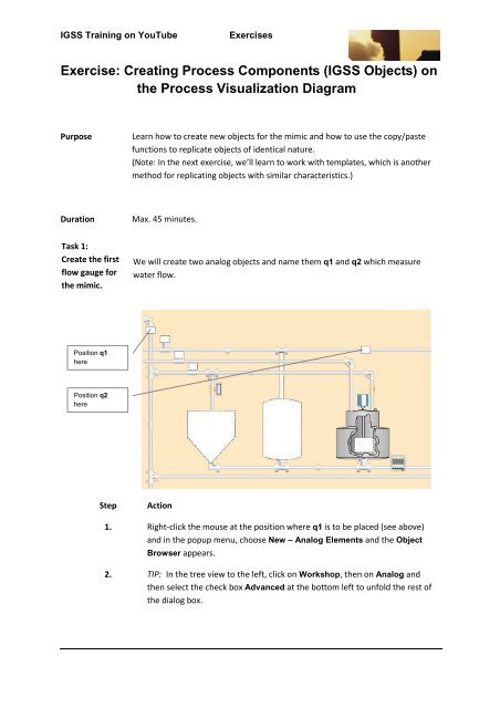
IGSS Training on YouTubeExercisesExercise: <strong>Creating</strong> Process Components (IGSS <strong>Objects</strong>) onthe Process Visualization DiagramPurposeLearn how to create new objects for the mimic and how to use the copy/pastefunctions to replicate objects of identical nature.(Note: In the next <strong>exercise</strong>, we’ll learn to work with templates, which is anothermethod for replicating objects with similar characteristics.)DurationMax. 45 minutes.Task 1:Create the firstflow gauge forthe mimic.We will create two analog objects and name them q1 and q2 which measurewater flow.Position q1herePosition q2hereStepAction1. Right-click the mouse at the position where q1 is to be placed (see above)and in the popup menu, choose New – Analog Elements and the ObjectBrowser appears.2. TIP: In the tree view to the left, click on Workshop, then on Analog andthen select the check box Advanced at the bottom left to unfold the rest ofthe dialog box.
IGSS Training on YouTubeExercises3. TIP: At the bottom right in the Name field, key in q1 and click Create andthe object properties dialog box appears as in the picture below.4. TIP: Go first to the Edit Mapping tab and under Atoms remove the checksfrom High Limit, Set Point, and Low Alarm and leave the rest selected.5. TIP: Key in or select the settings in the table below to complete the creationof the q1 process component.Tab Name Parameter Input parameter(s)Analog Description Flow water inMax./Min (range) Max. = 100 and Min. = 0Decimal Point (numberof decimals shown.)UnitsHigh Alarm(select the check box)Actual Value1(Leave blank until you come to optional task at theend of this <strong>exercise</strong>)95.062.0 (initial value)Page 2 of 13
IGSS Training on YouTubeExercisesSymbol DefinitionIn the Choose symbolgroup in Symbol Tablechoose Analogelements…and choose the symbol below.Task 2:Create thesecond flowgauge for themimic.Now you're finished creating the first flow gauge, q1. Go on to create the nextone, which you name q2.Now we'll create the q2 gauge by copying it from q1.StepAction1. Right click on q1 and choose Copy from the drop down menu.2. Right click again and choose Paste and then As new object and theoriginal q1 is replicated but with a new name. (Why is this?)3. Drag the new object to its correct position on the right side of the mimic(see the graphic above) and then rename it to q2 and change the PLCaddress (Edit Mapping tab) of the atom Actual Value. (Why do this?)This completes creating the two flow gauges.Task 3:Create a counterobjectNow we’ll create another type of IGSS object called a Counter object. This object,called C1, will be used to count the operational hours of a mixer motor, whichwe’ll create at a later time. For now, we'll create the object and place it as shownon the diagram below.Page 4 of 13
IGSS Training on YouTubeExercisesPosition C1 hereStepAction1. We will use a new graphical element to represent this object.On the menu go <strong>Objects</strong> Rectangular Field and in the tree view of theBrowser select Workshop then click on Counter.2. Key in the name C1 and click Create. When the object properties dialog boxappears, key in in the Desc. field operational hours for mixer.3 Now follow carefully the instructions below for the remainder of the settingsfor the C1 object.Tab Name Setting Input parameter(s)COUNTER Units (Leave blank until optional task at the end of<strong>exercise</strong>)Current countLimit (check)Preset valueMaximum valueCurrent count = 100 (initial value), Limit =150, Preset = 15 and Max. = 200DATA MANAGEMENTDEF.Scan interval5000 millisecondsLogging >5 %Base interval10 min.Page 5 of 13
IGSS Training on YouTubeExercisesData reductionTransfer toHistoryMinimum. and Maximum.Reduced ValueDISPLAY Show Under Name select Enable and underState/Value select EnableEDIT MAPPINGAtomCommandCountPresetKey in under PLC addresses for …DG = 24, WO = 1, BO = 0, Ext. type = FP16S.DG = 23, WO = 0, BO = 0, Ext. type = FP16S.DG = 24, WO = 2, BO = 0, Ext. type = FP16S.Alarm DetailsCreate an alarm text for Limit: Counterlimit exceeded, Priority = 10, Alarmcolor red and Blink enabled, Instructions:Use auxillary mixerATTRIBUTES OF ARECTANGLEFrame and Border Select Enable and then click on the Settingsbutton.Frame/BorderSettingsClick the button Frame Color and choose adark red color.In Frame Thickness choose 5.Click OK.to finish and save.Task 4:<strong>Creating</strong> astandard digitalpump withAnimatedSymbolOur next task is to place a simple on-off pump on the mimic and represent itwith a graphic from the Animated Symbol library.StepAction1. In the menu go View Drawing Toolbar to open the toolbar.2.Find the symbol and left click on it while dragging it onto the diagram where itappears as a black square.3. Click on the black square and a graphic for a blower appears.4. Double click the graphic and the properties page for Animated Symbol appears.Page 6 of 13
IGSS Training on YouTubeExercises5. Use the scroll bar on the left to come down to the category Pumps and select oneof the pumps in the second line.Select the check box Stretchable and observe what happens to the graphic.6. Click OK and the graphic comes onto the diagram.7. Position the pump graphic as shown belowPage 7 of 13
IGSS Training on YouTubeExercises.8. On the menu go <strong>Objects</strong> New Unreferenced… and the Object Browser comesup. We are creating a digital object which has no display.9. In the tree view on the left make sure you select Workshop, click on the + andthen click on the folder Digital and then (None).10. At the bottom of the Object Browser under Name: type in the name for thepump, p4 and a description, 2-state.11. Click Create and the object properties tabs appear. Notice there’s no Display tab.12. Go to the Data Management tab and key in the following:Scan interval: 5000Base interval: 5Data reduction: Change13. Go on to the Edit Mapping tab and choose the following settings.Highlight Command and on I/O mode: choose localHighlight State and on I/O mode: choose local14. Click OK and the properties tabs close.15. On the diagram, right click on the pump graphic and select Connect….Page 8 of 13
IGSS Training on YouTubeExercises16. In the Object Browser find and select the pump p4 and click the buttonOpen/Select and the pump graphic is connected to the object properties wedefined for p4 and we see now that a new tab has been added to the propertiestabs for the pump, namely Animated Symbol.17. Go to the Animated Symbol tab and do the following:In the upper right hand corner in the drop down box with the default setting Inalarm, select the
IGSS Training on YouTubeExercisesStepAction1. Click on the p4 graphic to open the properties tabs and go to theCalculation tab..2. Under Atom choose Command and under the Execution triggergroup select On object changes in expression.3. In the Expression group, key in the following expression in the blankfield: IIF(Value('q1')>28, 0,1)(NOTE: There is a space between the comma and the zero in the lineabove. If not written exactly as shown, an error will be displayed.)This tells the system that if the value of q1 exceeds 28 m3/hr. thenp4 must be stopped (0), otherwise p4 must run (1).4. Click the button Test Expression… to verify that the syntax iscorrect.5. In the Comment field key in a short description of what’s happening,for instance "The pump runs until the flow on q1 is greater than 28,then it's automatically stopped."6. Click OK to complete.Page 10 of 13
IGSS Training on YouTubeExercises7. Click on the symbol for the flow gauge q1 and go to the Calculationtab and put in the same settings as in the illustration below.8. When finished with entering the settings, click the Test Expression…button to verify correct syntax.9. Click OK.10. Save and install the configuration and correct any errors.11. Activate IGSS Starter and observe when p4 is stopped and startedagain.EXPLANATION:Atom we choose the Actual Value atom to manipulate with our expressionExecution trigger we choose to have the expression executed on the basis oftime intervals, On timer, Timer value (in mSecs)in this case 3000 millisecondsPage 11 of 13
IGSS Training on YouTubeExercisesExpression We want the 4 units to be added to the Actual Value of the flowgauge (Value('q1')+4), and when the maximum range of q1 is reached, whichis100, then we want to start anew with the Actual Value being set to zero, MOD100.Only execute expression if this condition is true We don’t want the additionof 4 units to occur until at least 3000 milliseconds have elapsed since the last time4 units were added, MsecsSinceLastExec()>3000RESULT: the q1 flow gauge will register an increase in flow with increments of 4until it reaches 100 at which time it will go back to zero and begin anew.OPTIONAL TASK:Create a newUnits set for usein definingobjectsDo this only if you have time left after completing the above tasks in this <strong>exercise</strong>.We wish to create a set of abbreviations for measurement units, which we willthen be able to choose for any object in our project. These will appear on the tabwhere the name of the object can be changed, for instance on the Analog tab foranalog objects.StepAction1. Open Edit Unit Sets…2. Click on New and key in the name Plant1 for the new Unit Set.3. Click Close to save and exit.4. Next, open Edit Measurement Units…5. Click on the button New and the Edit Base Unit dialogue appears.6. In the field Unit text key in the name of the measurement unitneeded, for instance m3/hr and in the Member of units setchoose Plant1 in the drop down box.Click OK.The dialog boxfor creating newunitsType in the name of theunit desiredChoose the newlycreated Plant1 fromdrop-down box.Page 12 of 13
IGSS Training on YouTubeExercises7. Repeat step 6. above to create 2 more unit texts called hrs. and m..8. Go back to the objects in the Exercise configuration and add theappropriate unit in the Units field, for instance on q1 go to theAnalog tab to find this field and use the drop down box to select theunit.YOU HAVE SUCCESSFULLY COMPLETED THE EXERCISE !!Page 13 of 13