Experimental model validation of an integrated process for the ...
Experimental model validation of an integrated process for the ...
Experimental model validation of an integrated process for the ...

Create successful ePaper yourself
Turn your PDF publications into a flip-book with our unique Google optimized e-Paper software.
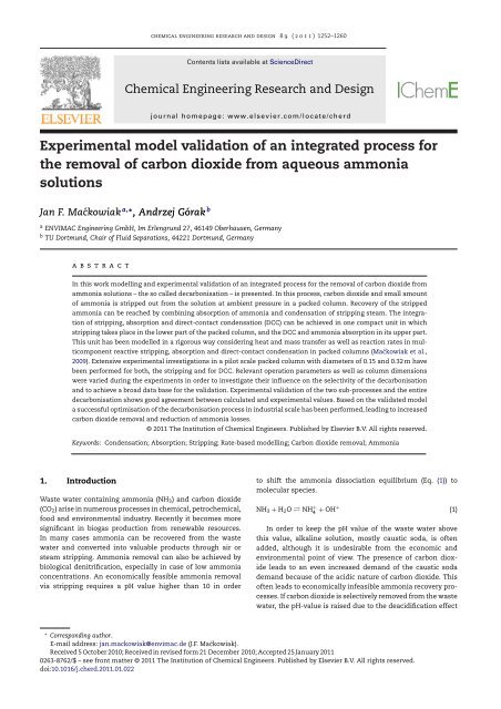
chemical engineering research <strong>an</strong>d design 8 9 ( 2 0 1 1 ) 1252–1260<br />
Contents lists available at ScienceDirect<br />
Chemical Engineering Research <strong>an</strong>d Design<br />
j ourna l ho me pa ge: www.elsevier.com/locate/cherd<br />
<strong>Experimental</strong> <strong>model</strong> <strong>validation</strong> <strong>of</strong> <strong>an</strong> <strong>integrated</strong> <strong>process</strong> <strong>for</strong><br />
<strong>the</strong> removal <strong>of</strong> carbon dioxide from aqueous ammonia<br />
solutions<br />
J<strong>an</strong> F. Maćkowiak a,∗ , Andrzej Górak b<br />
a ENVIMAC Engineering GmbH, Im Erlengrund 27, 46149 Oberhausen, Germ<strong>an</strong>y<br />
b TU Dortmund, Chair <strong>of</strong> Fluid Separations, 44221 Dortmund, Germ<strong>an</strong>y<br />
a b s t r a c t<br />
In this work <strong>model</strong>ling <strong>an</strong>d experimental <strong>validation</strong> <strong>of</strong> <strong>an</strong> <strong>integrated</strong> <strong>process</strong> <strong>for</strong> <strong>the</strong> removal <strong>of</strong> carbon dioxide from<br />
ammonia solutions – <strong>the</strong> so called decarbonisation – is presented. In this <strong>process</strong>, carbon dioxide <strong>an</strong>d small amount<br />
<strong>of</strong> ammonia is stripped out from <strong>the</strong> solution at ambient pressure in a packed column. Recovery <strong>of</strong> <strong>the</strong> stripped<br />
ammonia c<strong>an</strong> be reached by combining absorption <strong>of</strong> ammonia <strong>an</strong>d condensation <strong>of</strong> stripping steam. The integration<br />
<strong>of</strong> stripping, absorption <strong>an</strong>d direct-contact condensation (DCC) c<strong>an</strong> be achieved in one compact unit in which<br />
stripping takes place in <strong>the</strong> lower part <strong>of</strong> <strong>the</strong> packed column, <strong>an</strong>d <strong>the</strong> DCC <strong>an</strong>d ammonia absorption in its upper part.<br />
This unit has been <strong>model</strong>led in a rigorous way considering heat <strong>an</strong>d mass tr<strong>an</strong>sfer as well as reaction rates in multicomponent<br />
reactive stripping, absorption <strong>an</strong>d direct-contact condensation in packed columns (Maćkowiak et al.,<br />
2009). Extensive experimental investigations in a pilot scale packed column with diameters <strong>of</strong> 0.15 <strong>an</strong>d 0.32 m have<br />
been per<strong>for</strong>med <strong>for</strong> both, <strong>the</strong> stripping <strong>an</strong>d <strong>for</strong> DCC. Relev<strong>an</strong>t operation parameters as well as column dimensions<br />
were varied during <strong>the</strong> experiments in order to investigate <strong>the</strong>ir influence on <strong>the</strong> selectivity <strong>of</strong> <strong>the</strong> decarbonisation<br />
<strong>an</strong>d to achieve a broad data base <strong>for</strong> <strong>the</strong> <strong>validation</strong>. <strong>Experimental</strong> <strong>validation</strong> <strong>of</strong> <strong>the</strong> two sub-<strong>process</strong>es <strong>an</strong>d <strong>the</strong> entire<br />
decarbonisation shows good agreement between calculated <strong>an</strong>d experimental values. Based on <strong>the</strong> validated <strong>model</strong><br />
a successful optimisation <strong>of</strong> <strong>the</strong> decarbonisation <strong>process</strong> in industrial scale has been per<strong>for</strong>med, leading to increased<br />
carbon dioxide removal <strong>an</strong>d reduction <strong>of</strong> ammonia losses.<br />
© 2011 The Institution <strong>of</strong> Chemical Engineers. Published by Elsevier B.V. All rights reserved.<br />
Keywords: Condensation; Absorption; Stripping; Rate-based <strong>model</strong>ling; Carbon dioxide removal; Ammonia<br />
1. Introduction<br />
Waste water containing ammonia (NH3) <strong>an</strong>d carbon dioxide<br />
(CO2) arise in numerous <strong>process</strong>es in chemical, petrochemical,<br />
food <strong>an</strong>d environmental industry. Recently it becomes more<br />
signific<strong>an</strong>t in biogas production from renewable resources.<br />
In m<strong>an</strong>y cases ammonia c<strong>an</strong> be recovered from <strong>the</strong> waste<br />
water <strong>an</strong>d converted into valuable products through air or<br />
steam stripping. Ammonia removal c<strong>an</strong> also be achieved by<br />
biological denitrification, especially in case <strong>of</strong> low ammonia<br />
concentrations. An economically feasible ammonia removal<br />
via stripping requires a pH value higher th<strong>an</strong> 10 in order<br />
to shift <strong>the</strong> ammonia dissociation equilibrium (Eq. (1)) to<br />
molecular species.<br />
NH3 + H2O ⇄ NH +<br />
4 + OH +<br />
In order to keep <strong>the</strong> pH value <strong>of</strong> <strong>the</strong> waste water above<br />
this value, alkaline solution, mostly caustic soda, is <strong>of</strong>ten<br />
added, although it is undesirable from <strong>the</strong> economic <strong>an</strong>d<br />
environmental point <strong>of</strong> view. The presence <strong>of</strong> carbon dioxide<br />
leads to <strong>an</strong> even increased dem<strong>an</strong>d <strong>of</strong> <strong>the</strong> caustic soda<br />
dem<strong>an</strong>d because <strong>of</strong> <strong>the</strong> acidic nature <strong>of</strong> carbon dioxide. This<br />
<strong>of</strong>ten leads to economically infeasible ammonia recovery <strong>process</strong>es.<br />
If carbon dioxide is selectively removed from <strong>the</strong> waste<br />
water, <strong>the</strong> pH-value is raised due to <strong>the</strong> deacidification effect<br />
∗ Corresponding author.<br />
E-mail address: j<strong>an</strong>.mackowiak@envimac.de (J.F. Maćkowiak).<br />
Received 5 October 2010; Received in revised <strong>for</strong>m 21 December 2010; Accepted 25 J<strong>an</strong>uary 2011<br />
0263-8762/$ – see front matter © 2011 The Institution <strong>of</strong> Chemical Engineers. Published by Elsevier B.V. All rights reserved.<br />
doi:10.1016/j.cherd.2011.01.022<br />
(1)
Nomenclature<br />
chemical engineering research <strong>an</strong>d design 8 9 ( 2 0 1 1 ) 1252–1260 1253<br />
Variables<br />
a specific packing surface area (m 2 m −3 )<br />
dc column diameter (m)<br />
E heat flux (W m −2 s −1 )<br />
FV gas capacity factor (Pa 0.5 )<br />
h molar enthalpy (kJ mol −1 )<br />
˙N i molar flow <strong>of</strong> component i (mol s −1 )<br />
k reaction rate const<strong>an</strong>t (m 3 kmol −1 s −1 )<br />
L molar liquid flow (mol s −1 )<br />
mD vapour load (kg m −2 h −1 )<br />
N molar flux (mol m −2 s −1 )<br />
T temperature ( ◦ C)<br />
u velocity (m s −1 )<br />
V molar vapour flow (mol s −1 )<br />
x liquid phase molar fraction (mol mol −1 )<br />
y vapour phase molar fraction (mol mol −1 )<br />
ı film thickness (m)<br />
�z height <strong>of</strong> a rate based <strong>model</strong> stage (m)<br />
ε void volume <strong>of</strong> <strong>the</strong> packing referred to empty<br />
column (m 3 m −3 )<br />
D degree <strong>of</strong> desorption acc. to eq. 8 (%)<br />
selectivity acc. to eq. 8 (%)<br />
Sub- <strong>an</strong>d superscripts<br />
C condensation<br />
D desorption<br />
exp experimental<br />
GB gas (vapour) bulk<br />
GF gas (vapour) film<br />
L liquid phase<br />
LB liquid bulk<br />
LF liquid film<br />
S stripping<br />
sim simulated<br />
V vapour phase<br />
without adding chemicals. Selective carbon dioxide removal<br />
(decarbonisation) prior to <strong>the</strong> actual ammonia stripping is<br />
<strong>the</strong>re<strong>for</strong>e beneficial. So far, no suitable <strong>process</strong> <strong>for</strong> <strong>the</strong> selective<br />
ammonia recovery at ambient pressure is known from <strong>the</strong><br />
literature. In some cases, high pressure <strong>process</strong>es are used<br />
to take adv<strong>an</strong>tage <strong>of</strong> <strong>the</strong> different pressure dependency <strong>of</strong><br />
<strong>the</strong> gas–liquid equilibrium <strong>of</strong> carbon dioxide <strong>an</strong>d ammonia<br />
in water to achieve a selective fractionation. At pressure <strong>of</strong><br />
up to 30 bar, only carbon dioxide is desorbed from <strong>the</strong> solution<br />
while ammonia remains in <strong>the</strong> liquid phase (Schmidt,<br />
1970; Yu et al., 2010). Such <strong>process</strong>es are not recommended<br />
<strong>for</strong> end-<strong>of</strong>-<strong>the</strong> pipe waste water treatment in chemical <strong>an</strong>d<br />
petrochemical industry <strong>an</strong>d are not applicable in st<strong>an</strong>d-alone<br />
environmental <strong>process</strong>ing, especially in biogas production.<br />
The DecaStripp © -<strong>process</strong> allows a decarbonisation at<br />
ambient pressure. Carbon dioxide is stripped out from <strong>the</strong><br />
solution simult<strong>an</strong>eously with ammonia. Recovery <strong>of</strong> <strong>the</strong><br />
stripped ammonia c<strong>an</strong> be reached by combining absorption<br />
<strong>of</strong> ammonia <strong>an</strong>d condensation <strong>of</strong> stripping steam in a subsequent<br />
step. The interaction <strong>of</strong> <strong>the</strong> different unit operations <strong>of</strong><br />
stripping, absorption <strong>an</strong>d direct-contact condensation (DCC)<br />
c<strong>an</strong> be achieved in one single packed column (see Fig. 1).<br />
The decarbonisation column consists <strong>of</strong> two sections which<br />
are directly interconnected. In <strong>the</strong> lower section, <strong>the</strong> pre-<br />
Fig. 1 – Decarbonisiation <strong>process</strong> <strong>for</strong> selective carbon<br />
dioxide removal at ambient pressure.<br />
heated solution is fed in on top <strong>an</strong>d steam from <strong>the</strong> reboiler<br />
flows counter-currently from <strong>the</strong> bottom, carrying <strong>the</strong> desorbed<br />
components toward <strong>the</strong> upper part. In <strong>the</strong> upper section,<br />
<strong>the</strong> steam is condensed directly into <strong>the</strong> condensing agent <strong>an</strong>d<br />
ammonia is absorbed simult<strong>an</strong>eously in <strong>the</strong> liquid. To avoid<br />
re-absorption <strong>of</strong> <strong>the</strong> carbon dioxide, <strong>the</strong> DCC-section has to<br />
be carefully designed to keep <strong>the</strong> low soluble carbon dioxide<br />
in <strong>the</strong> vapour phase. A high selectivity <strong>of</strong> <strong>the</strong> CO2 removal<br />
is desired in <strong>the</strong> desorption part in order to achieve a high<br />
degree <strong>of</strong> decarbonisation. The decarbonised solution leaves<br />
<strong>the</strong> column at <strong>the</strong> bottom <strong>an</strong>d c<strong>an</strong> be fur<strong>the</strong>r treated in order<br />
to recover ammonia. The efficiency <strong>of</strong> <strong>the</strong> entire ammonia<br />
recovery <strong>process</strong> is signific<strong>an</strong>tly affected by <strong>the</strong> design <strong>of</strong> <strong>the</strong><br />
decarbonisation stage.<br />
The <strong>model</strong>ling <strong>of</strong> this complex <strong>integrated</strong> <strong>process</strong> requires<br />
<strong>an</strong> adequate, experimentally validated <strong>model</strong>ling framework.<br />
The application <strong>of</strong> <strong>the</strong> rate-based approach <strong>for</strong> <strong>the</strong> <strong>model</strong>ling<br />
<strong>of</strong> multicomponent reactive separation <strong>process</strong>es has proved<br />
to be superior to o<strong>the</strong>r concepts like <strong>the</strong> equilibrium stage<br />
<strong>model</strong>. The rate-based approach is physically more consistent<br />
<strong>an</strong>d overcomes <strong>the</strong> drawbacks <strong>of</strong> multicomponent efficiencies<br />
or HETP concept.<br />
The relev<strong>an</strong>ce <strong>of</strong> a <strong>model</strong> which shall be used <strong>for</strong><br />
design purposes is highly affected by <strong>the</strong> quality <strong>of</strong> available<br />
experimental data used <strong>for</strong> <strong>the</strong> <strong>model</strong> <strong>validation</strong>. For<br />
m<strong>an</strong>y relev<strong>an</strong>t industrial <strong>process</strong>es, data from <strong>the</strong> literature<br />
is scarce. The same is true <strong>for</strong> <strong>the</strong> NH3–CO2–H2O system,<br />
especially in connection with a selective carbon dioxide<br />
removal from aqueous solutions. In order to provide data<br />
<strong>for</strong> <strong>the</strong> presented <strong>model</strong> extensive experiments have to be<br />
per<strong>for</strong>med.<br />
2. Rate-based <strong>model</strong>ling<br />
The core element <strong>of</strong> <strong>the</strong> rate-based <strong>model</strong> is <strong>an</strong> axial segment<br />
<strong>of</strong> a packed column in which simult<strong>an</strong>eous mass tr<strong>an</strong>sfer <strong>an</strong>d
1254 chemical engineering research <strong>an</strong>d design 8 9 ( 2 0 1 1 ) 1252–1260<br />
Fig. 2 – Structure <strong>of</strong> <strong>an</strong> axial segment <strong>of</strong> <strong>the</strong> column according to <strong>the</strong> film <strong>the</strong>ory.<br />
chemical reactions are described according to <strong>the</strong> extended<br />
film <strong>model</strong> (see Fig. 2). The <strong>model</strong> is based on separately <strong>for</strong>mulated<br />
mass <strong>an</strong>d heat bal<strong>an</strong>ces <strong>for</strong> <strong>the</strong> vapour <strong>an</strong>d liquid<br />
phases (Kenig <strong>an</strong>d Górak, 1995; Kucka et al., 2003). These bal<strong>an</strong>ces<br />
are linked by <strong>the</strong> interfacial heat <strong>an</strong>d mass fluxes, E<br />
<strong>an</strong>d N i, which are equal <strong>for</strong> both phases. Thermodynamic<br />
equilibrium between <strong>the</strong> phases is assumed at <strong>the</strong> interface.<br />
According to <strong>the</strong> film <strong>model</strong>, <strong>the</strong> resist<strong>an</strong>ce to mass <strong>an</strong>d heat<br />
tr<strong>an</strong>sfer is placed in thin films adjacent to <strong>the</strong> phase boundary.<br />
Chemical reactions in <strong>the</strong> system NH3–CO2–H2O influence<br />
<strong>the</strong> ammonia <strong>an</strong>d carbon dioxide concentrations in <strong>the</strong> liquid<br />
phase <strong>an</strong>d thus <strong>the</strong> gas–liquid equilibrium. Reaction equilibrium<br />
<strong>an</strong>d kinetics are considered in both <strong>the</strong> liquid film<br />
<strong>an</strong>d bulk phase. Usually, <strong>the</strong> gas-liquid equilibrium in <strong>the</strong><br />
NH3–CO2–H2O system is determined by 5 key reactions (Eqs.<br />
(3)–(7), see e.g. Edwards et al., 1978). As kinetics <strong>of</strong> <strong>the</strong> reaction<br />
are considered as well in <strong>the</strong> developed <strong>model</strong>, <strong>the</strong> reaction <strong>of</strong><br />
carbon dioxide with hydroxide ions (Eq. (2)) becomes signific<strong>an</strong>t<br />
in <strong>the</strong> studied caustic pH value r<strong>an</strong>ge (D<strong>an</strong>ckwerts, 1970;<br />
Pohorecki <strong>an</strong>d Moniuk, 1988).<br />
CO2 + OH −<br />
kf 1<br />
⇄<br />
krev1 HCO −<br />
3<br />
k f 2<br />
⇄<br />
NH3 + HCO −<br />
3 NH2COO<br />
krev2 − + H2O (3)<br />
kf 3<br />
CO2 + 2H2O ⇄ HCO<br />
krev3 −<br />
3 + H3O +<br />
NH3 + H2O ⇄ NH +<br />
4 + OH −<br />
HCO −<br />
3 + H2O ⇄ H3O + + CO 2−<br />
3<br />
2H2O ⇄ H3O + + OH −<br />
In multicomponent mixtures <strong>the</strong> component fluxes across<br />
<strong>the</strong> interface are usually calculated using <strong>the</strong> Maxwell–Stef<strong>an</strong><br />
equations, which consider diffusional interactions between<br />
<strong>the</strong> particular species, which c<strong>an</strong> affect <strong>the</strong> tr<strong>an</strong>sport rates<br />
(Taylor <strong>an</strong>d Krishna, 1993). In a previous work (Maćkowiak<br />
et al., 2009), <strong>the</strong> linearized <strong>the</strong>ory presented by Toor (1964)<br />
<strong>an</strong>d Stewart <strong>an</strong>d Prober (1964) has been applied to h<strong>an</strong>dle <strong>the</strong><br />
Maxwell–Stef<strong>an</strong> equations <strong>for</strong> <strong>the</strong> diffusive mass tr<strong>an</strong>sfer in<br />
<strong>the</strong> film region. Its main assumption, which has proven to be<br />
<strong>of</strong> excellent accuracy <strong>for</strong> <strong>the</strong> majority <strong>of</strong> mass tr<strong>an</strong>sfer <strong>process</strong>es,<br />
is that diffusion coefficients remain const<strong>an</strong>t in <strong>the</strong><br />
film region. Several works (Huepen <strong>an</strong>d Kenig, 2005; Kucka<br />
(2)<br />
(4)<br />
(5)<br />
(6)<br />
(7)<br />
et al., 2003; Thiele et al., 2007) showed that simplified <strong>model</strong>s<br />
like <strong>the</strong> effective diffusivity method are sufficient in order to<br />
describe most reactive absorption <strong>process</strong>es because <strong>of</strong> negligible<br />
diffusional interactions between components. This is<br />
basically due to <strong>the</strong> diluted systems <strong>of</strong>ten applied in absorption<br />
<strong>an</strong>d is as well true <strong>for</strong> (reactive) desorption <strong>process</strong>es<br />
(Maćkowiak et al., 2009). The complexity <strong>of</strong> <strong>the</strong> <strong>model</strong> <strong>an</strong>d calculation<br />
time c<strong>an</strong> <strong>the</strong>re<strong>for</strong>e be reduced. This assumption holds<br />
as well <strong>for</strong> <strong>the</strong> desorption <strong>process</strong> applied in decarbonisation<br />
<strong>of</strong> waste water. A detailed comparison <strong>of</strong> <strong>the</strong> two <strong>model</strong>s<br />
showed, that deviations between <strong>the</strong> two calculation methods<br />
c<strong>an</strong> be neglected <strong>for</strong> <strong>the</strong> stripping section <strong>of</strong> <strong>the</strong> decarbonisation<br />
<strong>process</strong> (Maćkowiak et al., 2009).<br />
This does not hold <strong>for</strong> multicomponent DCC, which is used<br />
in <strong>the</strong> decarbonisation <strong>process</strong>. Here, <strong>the</strong> (at least) ternary<br />
vapour phase is usually not diluted <strong>an</strong>d diffusional interactions<br />
may not be neglected. Deviations in mass tr<strong>an</strong>sfer<br />
fluxes between <strong>the</strong> Maxwell–Stef<strong>an</strong> <strong>an</strong>d <strong>the</strong> effective diffusivity<br />
method increase <strong>for</strong> <strong>the</strong> DCC compared to <strong>the</strong> desorption<br />
Fig. 3 – Test facilities consisting <strong>of</strong> various test columns <strong>for</strong><br />
vapour(gas)/liquid separation <strong>process</strong>es with diameters<br />
from 0.15 to 0.5 m <strong>an</strong>d packing height <strong>of</strong> up to 10 m.
chemical engineering research <strong>an</strong>d design 8 9 ( 2 0 1 1 ) 1252–1260 1255<br />
Fig. 4 – <strong>Experimental</strong> set up <strong>for</strong> <strong>the</strong> investigation <strong>of</strong> desorption (steam stripping) <strong>an</strong>d direct-contact condensation <strong>process</strong>es<br />
in <strong>the</strong> NH3–CO2–H2O system.<br />
<strong>process</strong>. This causes, <strong>for</strong> practical purposes even more import<strong>an</strong>t,<br />
a signific<strong>an</strong>t difference between <strong>the</strong> calculated vapour<br />
outlet concentrations <strong>of</strong> ammonia, carbon dioxide <strong>an</strong>d water<br />
which in some cases exceeds 25%. These deviations which<br />
have been observed during <strong>the</strong> <strong>the</strong>oretical <strong>an</strong>alysis <strong>of</strong> <strong>the</strong><br />
<strong>process</strong> (Maćkowiak et al., 2009), c<strong>an</strong> be regarded as critical<br />
<strong>for</strong> column design, especially when ammonia emission limits<br />
have to be obeyed. There<strong>for</strong>e <strong>the</strong> effective diffusivity method is<br />
applied to calculate mass tr<strong>an</strong>sfer fluxes in <strong>the</strong> stripping section<br />
<strong>an</strong>d <strong>the</strong> Maxwell–Stef<strong>an</strong> equations <strong>for</strong> <strong>the</strong> DCC section in<br />
<strong>the</strong> decarbonisation <strong>process</strong>.<br />
The <strong>model</strong>s have been implemented into <strong>the</strong> commercial<br />
simulation environment Aspen Custom Modeler © , which<br />
provides a fully numerical algorithm to solve <strong>the</strong> system <strong>of</strong><br />
rate-based equations. The simulation tool <strong>of</strong>fers a direct link<br />
to <strong>the</strong> s<strong>of</strong>tware package Aspen Properties © <strong>for</strong> <strong>the</strong> calculation<br />
<strong>of</strong> <strong>the</strong> required physical properties. A subdivision <strong>of</strong> <strong>the</strong><br />
liquid <strong>an</strong>d <strong>the</strong> gas/vapour film into discrete elements allows<br />
<strong>the</strong> description <strong>of</strong> <strong>the</strong> nonlinear concentration <strong>an</strong>d temperature<br />
pr<strong>of</strong>iles. Packing specific fluid dynamics (Maćkowiak,<br />
2009), relev<strong>an</strong>t mass tr<strong>an</strong>sfer correlations (Maćkowiak, 2008)<br />
<strong>an</strong>d <strong>the</strong> component specific reaction rates are accounted <strong>for</strong><br />
by adequate sub-<strong>model</strong>s. The description <strong>of</strong> external elements<br />
like reboilers <strong>an</strong>d heat exch<strong>an</strong>gers complement <strong>the</strong> <strong>model</strong>.<br />
Detailed <strong>model</strong> equations are shown elsewhere (Maćkowiak<br />
et al., 2009).<br />
3. <strong>Experimental</strong> set-up<br />
In order to provide relev<strong>an</strong>t data <strong>for</strong> a <strong>model</strong> <strong>validation</strong>, <strong>an</strong><br />
extensive experimental investigation has been per<strong>for</strong>med in<br />
pilot scale packed columns. There<strong>for</strong>e semi-industrial scale<br />
packed columns have been used to study desorption via steam<br />
Table 1 – Varied parameters during <strong>the</strong> experimental <strong>an</strong>alysis <strong>of</strong> <strong>the</strong> desorption <strong>an</strong>d DCC <strong>process</strong> using lattice type<br />
McPac 1 <strong>an</strong>d 2 r<strong>an</strong>dom packings.<br />
Desorption <strong>an</strong>d DCC Symbol (unit) R<strong>an</strong>ge<br />
McPac r<strong>an</strong>dom packings a (m2 m−3 )/ε (m3 m−3 ) 90–185/0.97<br />
Column diameter dc,i (m) 0.15–0.316<br />
Packing height <strong>for</strong> each segment H (m) 0.9–5.3<br />
Liquid load uL (m3 m−2 h−1 ) 6–26<br />
Gas capacity factor FV (Pa0.5 ) 0.1–2.5<br />
Liquid feed concentrations (desorption) cin /c NH3 in<br />
Vapour feed concentrations (DCC)<br />
(mol/l) CO2 y<br />
(0.12–0.31)/(0.08–0.27)<br />
in /y NH3 in<br />
Liquid feed temperature<br />
(vol.%) CO2 T (<br />
(1–5)/(1–25)<br />
◦C) 80–98
1256 chemical engineering research <strong>an</strong>d design 8 9 ( 2 0 1 1 ) 1252–1260<br />
Fig. 5 – Simulated concentration pr<strong>of</strong>iles <strong>an</strong>d experimental<br />
values <strong>of</strong> a desorption experiment with high selectivity in<br />
<strong>the</strong> NH3–CO2–H2O system.<br />
stripping <strong>an</strong>d <strong>the</strong> DCC <strong>process</strong> in <strong>the</strong> system NH3–CO2–H2O<br />
separately. The separate investigation <strong>of</strong> <strong>the</strong> two unit operations<br />
avoids interactions <strong>of</strong> <strong>the</strong> varied operating parameters<br />
which might occur due to <strong>the</strong> interconnection <strong>of</strong> both <strong>process</strong>es<br />
in <strong>the</strong> decarbonisation column.<br />
The test columns are part <strong>of</strong> a fully automated R&D facility<br />
<strong>for</strong> various fluid separation <strong>process</strong>es operated by Envimac<br />
Engineering, see Fig. 3. The test columns have been especially<br />
designed <strong>for</strong> flexible adjustment to <strong>the</strong> requirements <strong>of</strong> distillation,<br />
absorption, stripping <strong>an</strong>d direct-contact condensation.<br />
Both <strong>process</strong>es studied in this work have been <strong>integrated</strong> in<br />
one steel column with a column diameter <strong>of</strong> dc,S = 0.316 m <strong>an</strong>d<br />
dc,C = 0.150 m <strong>an</strong>d a total height <strong>of</strong> up to 10 m, see Figs. 3 <strong>an</strong>d 4.<br />
A steam generator supplies steam <strong>for</strong> both heating <strong>an</strong>d stripping,<br />
it c<strong>an</strong> be used to heat up <strong>the</strong> reboiler or it is fed directly<br />
into <strong>the</strong> bottom <strong>of</strong> <strong>the</strong> multifunctional column. Above, <strong>the</strong><br />
stripping section is installed. The vapour mixture <strong>of</strong> <strong>the</strong> stripping<br />
section is used as feed <strong>for</strong> <strong>the</strong> DCC section.<br />
In order to avoid interactions, <strong>the</strong> condensate from <strong>the</strong><br />
upper section is collected on a collector tray <strong>an</strong>d removed from<br />
<strong>the</strong> column via a side stream. The vapour passes <strong>the</strong> collector<br />
tray through chimneys. The condensing agent enters <strong>the</strong><br />
column at ambient conditions on top <strong>of</strong> <strong>the</strong> column.<br />
The pilot pl<strong>an</strong>t is equipped with state-<strong>of</strong> <strong>the</strong> art measurement<br />
devices <strong>an</strong>d a highly automated Siemens S7 <strong>process</strong><br />
control system. This ensures high accuracy <strong>an</strong>d reproducibility<br />
<strong>of</strong> <strong>the</strong> experiments, shown by <strong>the</strong> adequate relative<br />
deviation in total mass bal<strong>an</strong>ce <strong>of</strong> maximal ±4% <strong>an</strong>d ±8%<br />
<strong>for</strong> both <strong>the</strong> carbon dioxide <strong>an</strong>d ammonia liquid side bal<strong>an</strong>ce.<br />
The ammonia concentrations in <strong>the</strong> liquid phase have<br />
been detected by a photometer, <strong>the</strong> carbon dioxide contents<br />
by titration.<br />
As a r<strong>an</strong>dom packing, McPac high per<strong>for</strong>m<strong>an</strong>ce packings<br />
<strong>of</strong> two different sizes have been chosen <strong>for</strong> <strong>the</strong> experiments<br />
(Maćkowiak, 2001). These packings have a very low tendency<br />
<strong>for</strong> fouling <strong>an</strong>d thus are especially suitable <strong>for</strong> “dirty” liquids<br />
as <strong>the</strong>y <strong>of</strong>ten occur in industrial separation <strong>process</strong>es.<br />
Fig. 6 – (a) <strong>Experimental</strong> degree <strong>of</strong> desorption <strong>of</strong> ammonia<br />
<strong>an</strong>d carbon dioxide as a function <strong>of</strong> <strong>the</strong> vapour load. On <strong>the</strong><br />
right axis additionally <strong>the</strong> resulting selectivity is shown. (b)<br />
<strong>Experimental</strong> <strong>an</strong>d simulated degrees <strong>of</strong> desorption <strong>for</strong> both<br />
components as well as corresponding selectivity as a<br />
function <strong>of</strong> liquid feed temperature. Error bars indicate<br />
±10% deviation.<br />
The size <strong>of</strong> <strong>the</strong> test columns requires <strong>an</strong> appropriate<br />
amount <strong>of</strong> feed solution, which <strong>the</strong>re<strong>for</strong>e was produced by dissolving<br />
NH4HCO3 in a 10 m3 feed t<strong>an</strong>k. The feed concentration<br />
<strong>of</strong> ammonia cNH varied between 2 <strong>an</strong>d 5 g/l, which is typical<br />
3<br />
<strong>for</strong> m<strong>an</strong>y kinds <strong>of</strong> waste waters, e.g. from biogas or coking<br />
industry. The main objective <strong>of</strong> <strong>the</strong> desorption part is a high<br />
selectivity <strong>of</strong> carbon dioxide compared to ammonia removal<br />
efficiency. The selectivity CO2,NH is calculated based on <strong>the</strong><br />
3<br />
removal efficiencies i<br />
D as follows:<br />
CO2 D<br />
CO2,NH = 3 − NH3 D<br />
CO2 D + NH3 D<br />
with<br />
i<br />
D = 1 −<br />
˙N L<br />
i,out<br />
˙N L<br />
× 100% (8)<br />
i,in<br />
The subscript D denotes that efficiency refers to <strong>the</strong> desorption<br />
<strong>process</strong>.<br />
In order to <strong>an</strong>alyse <strong>the</strong> separation efficiency <strong>of</strong> <strong>the</strong> stripping<br />
part, <strong>the</strong> influencing parameters like liquid <strong>an</strong>d vapour load,
chemical engineering research <strong>an</strong>d design 8 9 ( 2 0 1 1 ) 1252–1260 1257<br />
packing height <strong>an</strong>d type, feed concentration <strong>an</strong>d temperature<br />
were varied over a wide r<strong>an</strong>ge (Table 1). The experiments in<br />
<strong>the</strong> condensing section are used to gain detailed underst<strong>an</strong>ding<br />
<strong>of</strong> <strong>the</strong> condensation <strong>process</strong> accomp<strong>an</strong>ied with absorption<br />
in packed columns. DCC in <strong>the</strong> system NH3–CO2–H2O c<strong>an</strong> be<br />
regarded as condensation in <strong>the</strong> presence <strong>of</strong> inerts, as <strong>the</strong> solubility<br />
<strong>of</strong> carbon dioxide in water is small enough under <strong>the</strong><br />
studied conditions to be neglected. Literature about multicomponent<br />
condensation <strong>process</strong>es with inerts in packed columns<br />
is very scarce, what justifies extensive experimental studies.<br />
This leads to a database consisting <strong>of</strong> 50 data records <strong>for</strong> <strong>the</strong><br />
desorption <strong>process</strong> <strong>an</strong>d 39 <strong>for</strong> <strong>the</strong> DCC <strong>process</strong>.<br />
4. Process <strong>an</strong>alysis <strong>an</strong>d <strong>model</strong> <strong>validation</strong><br />
Based on <strong>the</strong> experimental results data reconciliation has<br />
been per<strong>for</strong>med <strong>for</strong> both <strong>the</strong> stripping <strong>an</strong>d <strong>the</strong> DCC <strong>process</strong><br />
in order to provide consistent input data <strong>for</strong> <strong>the</strong> simulations.<br />
There<strong>for</strong>e <strong>the</strong> measured flow rates <strong>an</strong>d concentrations were<br />
varied within <strong>the</strong>ir specific toler<strong>an</strong>ces until consistent component<br />
bal<strong>an</strong>ces were achieved. The <strong>an</strong>alysis <strong>of</strong> <strong>the</strong> experiments<br />
is based on <strong>the</strong> consideration <strong>of</strong> removal efficiencies <strong>for</strong> both<br />
ammonia <strong>an</strong>d carbon dioxide <strong>an</strong>d <strong>the</strong> resulting selectivity. The<br />
following chapters describe <strong>the</strong> <strong>process</strong> <strong>an</strong>alysis <strong>an</strong>d <strong>the</strong> <strong>validation</strong><br />
<strong>of</strong> <strong>the</strong> rate based <strong>model</strong>s separately, according to <strong>the</strong><br />
per<strong>for</strong>med experiments.<br />
4.1. Stripping section<br />
The presented rate-based <strong>model</strong> allows <strong>for</strong> <strong>the</strong> description <strong>of</strong><br />
concentration <strong>an</strong>d temperature pr<strong>of</strong>iles along <strong>the</strong> packed column.<br />
A comparison <strong>of</strong> calculated concentration pr<strong>of</strong>iles <strong>an</strong>d<br />
experimental output at reconciled input values <strong>for</strong> a desorption<br />
experiment is shown in Fig. 5. It shows that most <strong>of</strong> <strong>the</strong><br />
carbon dioxide is already desorbed near <strong>the</strong> top <strong>of</strong> <strong>the</strong> column.<br />
Even low carbonate concentrations cause <strong>an</strong> increased chemical<br />
dem<strong>an</strong>d in <strong>the</strong> following ammonia removal steps, thus<br />
<strong>the</strong> bed length should be long enough to achieve maximum<br />
removal efficiency. Fur<strong>the</strong>rmore, it shows that <strong>the</strong> desorption<br />
rate <strong>of</strong> ammonia c<strong>an</strong> be held to a small value, when operating<br />
conditions are chosen appropriately. Thus, high selectivities<br />
<strong>of</strong> around 90% c<strong>an</strong> be achieved.<br />
The gas <strong>an</strong>d liquid load has signific<strong>an</strong>t influence on <strong>the</strong><br />
selectivity <strong>of</strong> ammonia <strong>an</strong>d carbon dioxide removal from <strong>the</strong><br />
liquid. Mass tr<strong>an</strong>sfer <strong>of</strong> NH3 in <strong>the</strong> binary NH3–H2O system is<br />
known to be controlled by gas <strong>an</strong>d liquid side resist<strong>an</strong>ce, thus<br />
vapour load has a larger influence on ammonia removal compared<br />
to <strong>the</strong> system CO2–H2O, which is basically controlled<br />
by <strong>the</strong> liquid side resist<strong>an</strong>ce. This effect is shown in Fig. 6a,<br />
<strong>the</strong> degree <strong>of</strong> desorption <strong>of</strong> ammonia is more sensitive to<br />
ch<strong>an</strong>ges <strong>of</strong> <strong>the</strong> vapour load th<strong>an</strong> <strong>the</strong> corresponding value <strong>for</strong><br />
carbon dioxide. Fig. 6b shows <strong>the</strong> influence <strong>of</strong> <strong>the</strong> liquid feed<br />
temperature on <strong>the</strong> desorption <strong>process</strong>. Beside <strong>the</strong> experimental<br />
values <strong>the</strong> simulated values are displayed additionally as<br />
lines in this diagram. High temperatures close to <strong>the</strong> boiling<br />
point <strong>of</strong> <strong>the</strong> solution thus enh<strong>an</strong>ce both, ammonia <strong>an</strong>d carbon<br />
dioxide desorption. The different dependency on temperature<br />
ch<strong>an</strong>ges leads to <strong>an</strong> optimal value in respect <strong>of</strong> <strong>the</strong> selectivity<br />
<strong>of</strong> around 90 ◦ C under <strong>the</strong> studied conditions. The simulated<br />
values agree well within ±10% with <strong>the</strong> experiments.<br />
During <strong>the</strong> experiments a dependency between <strong>the</strong> desorption<br />
<strong>of</strong> carbon dioxide <strong>an</strong>d ammonia, <strong>an</strong>d <strong>the</strong> inlet<br />
concentration ratio <strong>of</strong> both components has been observed.<br />
Fig. 7 – (a) Parity plot <strong>for</strong> all per<strong>for</strong>med desorption<br />
experiments compared to <strong>the</strong> rate-based <strong>model</strong> based on<br />
removal efficiencies according to Eq. (2). (b) Corresponding<br />
parity plot <strong>for</strong> <strong>the</strong> selectivity <strong>of</strong> <strong>the</strong> carbon dioxide<br />
stripping.<br />
Increasing ratio <strong>of</strong> carbon dioxide to ammonia inlet concentration<br />
leads to higher selectivity <strong>of</strong> <strong>the</strong> separation <strong>process</strong> due to<br />
increased carbon dioxide <strong>an</strong>d decreasing ammonia removal.<br />
The observed dependency c<strong>an</strong>not be explained by consideration<br />
<strong>of</strong> only binary mass tr<strong>an</strong>sfer effects. As a consequence, <strong>the</strong><br />
carbamate-reaction describing chemical interaction between<br />
ammonia <strong>an</strong>d carbon dioxide (Eq. (3)) should not be neglected<br />
even at high temperatures <strong>of</strong> up to 100 ◦ C.<br />
To summarise all per<strong>for</strong>med experiments, Fig. 7a shows a<br />
parity plot <strong>for</strong> all desorption experiments based on degrees<br />
<strong>of</strong> desorption <strong>for</strong> both ammonia <strong>an</strong>d carbon dioxide <strong>an</strong>d <strong>the</strong><br />
simulated values. It c<strong>an</strong> be stated that <strong>the</strong> <strong>model</strong> reproduces
1258 chemical engineering research <strong>an</strong>d design 8 9 ( 2 0 1 1 ) 1252–1260<br />
Fig. 8 – Flow pr<strong>of</strong>ile <strong>of</strong> NH3 <strong>an</strong>d CO2 along <strong>the</strong> packed bed<br />
in <strong>the</strong> DCC section.<br />
<strong>the</strong> experiments within a maximum deviation <strong>of</strong> ±20% <strong>for</strong> <strong>the</strong><br />
conditions shown in Table 1. The average deviation between<br />
experimental <strong>an</strong>d simulated values is 7.4% <strong>for</strong> <strong>the</strong> carbon dioxide<br />
values <strong>an</strong>d 12% <strong>for</strong> <strong>the</strong> ammonia values. This difference is<br />
caused by <strong>the</strong> different accuracy <strong>of</strong> <strong>the</strong> applied specific <strong>an</strong>alytic<br />
method. The <strong>model</strong> c<strong>an</strong> <strong>the</strong>re<strong>for</strong>e be used <strong>for</strong> design<br />
as well as <strong>for</strong> optimisation <strong>of</strong> desorption <strong>process</strong>es. Fig. 7b<br />
displays <strong>the</strong> resulting selectivities during <strong>the</strong> experiments<br />
compared to <strong>the</strong> simulated values.<br />
Fig. 7b shows, that during <strong>the</strong> per<strong>for</strong>med experiments not<br />
only high selectivites <strong>of</strong> up to 90% have been achieved, but<br />
not appropriate operating conditions may lead to very low<br />
selectivities, mainly caused by to high ammonia desorption<br />
rates. Even negative values <strong>of</strong> <strong>the</strong> selectivity were observed,<br />
in this case <strong>the</strong> degree <strong>of</strong> desorption <strong>of</strong> ammonia exceeds<br />
<strong>the</strong> value <strong>for</strong> carbon dioxide. This fact underlines that selective<br />
desorption <strong>of</strong> carbon dioxide from aqueous ammonia<br />
solutions is possible, but operating conditions have to be<br />
carefully designed because <strong>of</strong> various interacting parameters,<br />
<strong>for</strong> this purpose <strong>the</strong> developed rate based <strong>model</strong> c<strong>an</strong> be<br />
used.<br />
4.2. Direct contact condensation section<br />
Fig. 8 shows a typical flow pr<strong>of</strong>ile <strong>for</strong> <strong>the</strong> total condensation<br />
<strong>of</strong> steam <strong>an</strong>d absorption <strong>of</strong> ammonia, where steam <strong>an</strong>d<br />
ammonia concentration in <strong>the</strong> vapour phase is reduced to a<br />
minimum, in comparison <strong>the</strong> carbon dioxide amount remains<br />
almost const<strong>an</strong>t. This proves <strong>the</strong> assumption <strong>of</strong> carbon dioxide<br />
being a quasi-inert in <strong>the</strong> studied vapour mixture.<br />
Molar flow rates are chosen to display <strong>the</strong> condensation<br />
<strong>an</strong>d selective absorption along <strong>the</strong> packed bed because molar<br />
overflow <strong>of</strong> <strong>the</strong> vapour decreases signific<strong>an</strong>tly during <strong>the</strong><br />
condensation <strong>process</strong> <strong>an</strong>d thus concentration pr<strong>of</strong>iles have<br />
limited me<strong>an</strong>ing.<br />
Compared to <strong>the</strong> DCC <strong>of</strong> pure vapours, which has been<br />
experimentally investigated in a different work, <strong>the</strong> presence<br />
<strong>of</strong> NH3 <strong>an</strong>d CO2 affects noticeably <strong>the</strong> condensation <strong>of</strong><br />
Fig. 9 – (a) Parity plot <strong>for</strong> liquid outlet molar flow <strong>of</strong><br />
ammonia in <strong>the</strong> direct contact condensing section. (b)<br />
Corresponding parity plot <strong>of</strong> experimental <strong>an</strong>d simulated<br />
vapour outlet temperatures.<br />
steam in <strong>the</strong> multicomponent mixture. Carbon dioxide c<strong>an</strong><br />
be regarded as a quasi-inert, which increases <strong>the</strong> mass tr<strong>an</strong>sfer<br />
resist<strong>an</strong>ce in <strong>the</strong> vapour phase compared to <strong>the</strong> pure<br />
vapour. There<strong>for</strong>e, <strong>the</strong> condensation efficiency decreases with<br />
increasing inert concentration what has to be considered<br />
during <strong>the</strong> design <strong>of</strong> <strong>the</strong> packed bed condenser. For <strong>the</strong> condensation<br />
<strong>of</strong> vapour from a mixture containing 10 vol.% <strong>of</strong><br />
<strong>an</strong> inert, den necessary condenser area might be up to 80%<br />
larger th<strong>an</strong> <strong>for</strong> <strong>the</strong> condensation <strong>of</strong> <strong>the</strong> same amount <strong>of</strong> pure<br />
vapour. This results in a 80% higher packing height in case<br />
<strong>of</strong> packed bed condenser with const<strong>an</strong>t column diameter.<br />
Such effects <strong>of</strong>ten c<strong>an</strong>not be described accurate enough using<br />
simple, basically empirical design correlations, because dif-
Fig. 10 – Typical temperature pr<strong>of</strong>ile <strong>of</strong> vapour <strong>an</strong>d liquid<br />
phase along <strong>the</strong> packed bed in <strong>the</strong> DCC section compared<br />
to <strong>the</strong> experimental values.<br />
chemical engineering research <strong>an</strong>d design 8 9 ( 2 0 1 1 ) 1252–1260 1259<br />
fusional interactions, simult<strong>an</strong>eous absorption <strong>of</strong> ammonia<br />
with its signific<strong>an</strong>t enthalpy <strong>of</strong> solution <strong>an</strong>d design parameters<br />
influence <strong>the</strong> condensation <strong>process</strong> simult<strong>an</strong>eously, what<br />
c<strong>an</strong> be considered using a rate-based <strong>model</strong>.<br />
For <strong>the</strong> DCC in packed columns, so far no reliable data<br />
<strong>for</strong> multicomponent condensation has been published. The<br />
parity plot in Fig. 9a shows that <strong>the</strong> experiments per<strong>for</strong>med<br />
in this work c<strong>an</strong> be reproduced with a similar precision as<br />
<strong>the</strong> desorption experiments. In condensation <strong>process</strong>es <strong>the</strong><br />
correct calculation <strong>of</strong> <strong>the</strong> temperatures plays a major role<br />
in condensation <strong>process</strong>es compared to <strong>the</strong> steam stripping<br />
<strong>process</strong>, where usually no signific<strong>an</strong>t temperatures gradients<br />
occur along <strong>the</strong> column. There<strong>for</strong>e, beside <strong>the</strong> mass tr<strong>an</strong>sfer<br />
related comparison Fig. 9b shows a parity plot <strong>of</strong> experimental<br />
<strong>an</strong>d simulated vapour outlet concentrations, which again<br />
show a satisfying accuracy.<br />
The presented rate-based <strong>model</strong> has <strong>the</strong>re<strong>for</strong>e been validated<br />
<strong>for</strong> <strong>the</strong> first time <strong>for</strong> direct contact condensation<br />
<strong>process</strong>es characterised by large temperature gradients along<br />
<strong>the</strong> column. A typical temperature pr<strong>of</strong>ile <strong>for</strong> <strong>the</strong> studied condensation<br />
<strong>process</strong> is shown in Fig. 10.<br />
Due to <strong>the</strong> inert, <strong>the</strong> vapour temperature decreases during<br />
<strong>the</strong> condensation <strong>process</strong>, leading to smaller driving <strong>for</strong>ces <strong>for</strong><br />
heat tr<strong>an</strong>sfer compared to <strong>the</strong> condensation <strong>of</strong> pure vapours.<br />
For design purposes <strong>the</strong> rate based <strong>model</strong> is strongly recommended.<br />
5. Conclusions<br />
A <strong>process</strong> <strong>for</strong> <strong>the</strong> selective removal <strong>of</strong> dissolved carbon dioxide<br />
from ammonia solutions (decarbonisiation) has been presented.<br />
The <strong>process</strong> consists <strong>of</strong> two steps, a desorption part,<br />
where carbon dioxide is stripped by me<strong>an</strong>s <strong>of</strong> steam <strong>an</strong>d a<br />
DCC part, where <strong>the</strong> steam is condensed <strong>an</strong>d gaseous ammonia<br />
is absorbed in a packed column. To describe <strong>the</strong> reactive<br />
multicomponent separation <strong>process</strong>es a rate-based <strong>model</strong> <strong>for</strong><br />
both steps has been developed based on previous works. The<br />
<strong>model</strong> has been implemented into Aspen Custom Modeler<br />
<strong>an</strong>d features Maxwell–Stef<strong>an</strong> equations to h<strong>an</strong>dle multicom-<br />
ponent mass tr<strong>an</strong>sfer <strong>for</strong> <strong>the</strong> DCC <strong>process</strong> as well as <strong>the</strong><br />
simplified effective diffusivity method which c<strong>an</strong> be applied<br />
with high accuracy <strong>for</strong> desorption <strong>process</strong>es in <strong>the</strong> system<br />
NH3–CO2–H2O. An extensive experimental <strong>an</strong>alysis <strong>of</strong> both<br />
desorption <strong>an</strong>d <strong>the</strong> DCC identified <strong>the</strong> sensitive operating<br />
parameters influencing <strong>the</strong> selectivity <strong>of</strong> carbon dioxide to<br />
ammonia removal <strong>for</strong> <strong>the</strong> desorption <strong>an</strong>d <strong>the</strong> DCC. The experiments<br />
have been per<strong>for</strong>med in pilot scale packed columns<br />
with diameter from 0.15 to 0.316 m <strong>an</strong>d a total column height<br />
<strong>of</strong> up to 10 m. Input concentrations <strong>of</strong> ammonia <strong>an</strong>d carbon<br />
dioxide <strong>an</strong>d <strong>the</strong> vapour <strong>an</strong>d liquid load have great influence<br />
on <strong>the</strong> selectivity <strong>of</strong> carbon dioxide removal. In contrast to <strong>the</strong><br />
binary system CO2–H2O, in which tr<strong>an</strong>sfer resist<strong>an</strong>ce is located<br />
mainly <strong>the</strong> liquid phase, <strong>the</strong> vapour load affects <strong>the</strong> ammonia<br />
removal signific<strong>an</strong>tly. The ammonia removal efficiencies thus<br />
vary from 3 to 80% depending on <strong>the</strong> operation point <strong>of</strong> <strong>the</strong><br />
column. As a result, selectivities <strong>of</strong> up to 90% c<strong>an</strong> be achieved<br />
in <strong>the</strong> decarbonisation <strong>process</strong>, resulting in <strong>an</strong> increase <strong>of</strong> <strong>the</strong><br />
outlet pH-value <strong>of</strong> up to 10.5, which is high enough to reduce<br />
<strong>the</strong> chemical dem<strong>an</strong>d in <strong>the</strong> following ammonia removal step<br />
by 90%.<br />
The experimental data has been successfully used to validate<br />
<strong>the</strong> <strong>model</strong>s, which is characterised by a satisfying<br />
accuracy under <strong>the</strong> studied conditions <strong>of</strong> max. ±20%. The<br />
r<strong>an</strong>ge <strong>of</strong> operating conditions <strong>an</strong>d <strong>the</strong> number <strong>of</strong> 50 data sets<br />
<strong>for</strong> <strong>the</strong> desorption <strong>an</strong>d 39 sets <strong>for</strong> <strong>the</strong> DCC allow a most convincing<br />
<strong>validation</strong> <strong>for</strong> reactive stripping <strong>an</strong>d direct contact<br />
condensation in packed columns resulting in a powerful tool<br />
<strong>for</strong> optimisation <strong>an</strong>d design purposes.<br />
Acknowledgements<br />
We highly appreciate <strong>the</strong> support <strong>of</strong> ENVIMAC Engineering<br />
GmbH as well as <strong>the</strong> Ziel-2-Projekt <strong>of</strong> Nordrhein-Westfalen<br />
<strong>an</strong>d <strong>the</strong> Europe<strong>an</strong> Union.<br />
References<br />
D<strong>an</strong>ckwerts, P.V., 1970. Gas–Liquid Reactions. McGraw-Hill, New<br />
York.<br />
Edwards, T.J., Maurer, G., Newm<strong>an</strong>n, J., Prausnitz, J.M., 1978.<br />
Vapour–liquid equilibria in multicomponent aqueous<br />
solutions <strong>of</strong> volatile weak electrolytes. AIChE J. 24 (6), 966–976.<br />
Huepen, B., Kenig, E.Y., 2005. Rigorous <strong>model</strong>ling on NOx<br />
absorption in tray <strong>an</strong>d packed columns. Chem. Eng. Sci. 60,<br />
6462–6471.<br />
Kenig, E.Y., Górak, A., 1995. A film <strong>model</strong> based approach <strong>for</strong><br />
simulation <strong>of</strong> multicomponent reactive separation. Chem.<br />
Eng. Process 34, 97–103.<br />
Kucka, L., Mueller, I., Kenig, E.Y., Górak, A., 2003. On <strong>the</strong><br />
<strong>model</strong>ling <strong>an</strong>d simulation <strong>of</strong> sour gas absorption by aqueous<br />
amine solutions. Chem. Eng. Sci. 58 (16), 3571–3578.<br />
Maćkowiak, J., 2001. McPac - Ein neuer metallischer Füllkörper für<br />
Gas/Flüssig-Systeme. Chem. Ing. Tech. 73 (1–2), 74–79.<br />
Maćkowiak, J., 2008. Modellierung des flüssigkeitsseitigen<br />
St<strong>of</strong>füberg<strong>an</strong>ges in Kolonnen mit klassischen und<br />
gitterförmigen Füllkörpern. Chem. Ing. Tech. 80 (1–2), 57–77.<br />
Maćkowiak, J., 2009. Fluid Dynamics <strong>of</strong> Packed Columns:<br />
Principles <strong>of</strong> <strong>the</strong> Fluid Dynamic Design <strong>of</strong> Columns <strong>for</strong><br />
Gas/Liquid <strong>an</strong>d Liquid/Liquid Systems. Springer, Berlin.<br />
Maćkowiak, J.F., Górak, A., Kenig, E.Y., 2009. Modelling <strong>of</strong><br />
combined direct contact condensation <strong>an</strong>d reactive<br />
absorption in packed columns. Chem. Eng. J. 149 (3), 362–369.<br />
Pohorecki, R., Moniuk, W., 1988. Kinetics <strong>of</strong> reaction between<br />
carbon dioxide <strong>an</strong>d hydroxyl ions in aqueous electrolyte<br />
solutions. Chem. Eng. Sci. 43 (7), 1677–1684.
1260 chemical engineering research <strong>an</strong>d design 8 9 ( 2 0 1 1 ) 1252–1260<br />
Schmidt, A., 1970. Ein neues Verfahren zur Trennung von<br />
Ammoniak und Kohlendioxid. Chem. Ing. Tech. 42 (8),<br />
521–523.<br />
Stewart, W.E., Prober, R., 1964. Matrix calculations <strong>of</strong><br />
multicomponent mass tr<strong>an</strong>sfer in iso<strong>the</strong>rmal systems. Ind.<br />
Eng. Chem. Fundam. 3, 224–235.<br />
Taylor, R., Krishna, R., 1993. Multicomponent Mass Tr<strong>an</strong>sfer, 1st<br />
ed. John Wiley & Sons, Inc., New York.<br />
Thiele, R., Faber, R., Repke, J.-U., Thielert, H., Wozny, G., 2007.<br />
Design <strong>of</strong> industrial reactive absorption <strong>process</strong>es in sour gas<br />
treatment using rigorous <strong>model</strong>ling <strong>an</strong>d accurate<br />
experimentation. Chem. Eng. Res. Des. 85, 74–87.<br />
Toor, H.L., 1964. Solution <strong>of</strong> <strong>the</strong> linearized equations <strong>of</strong><br />
multicomponent mass tr<strong>an</strong>sfer. AIChE J. 10, 448–455, pp.<br />
460–465.<br />
Yu, H., Morg<strong>an</strong>, S., Allport, A., Do, T., Cotrell, A., McGregor, J.,<br />
Feron, P., 2010. Update on aqueous ammonia based post<br />
combustion capture pilot pl<strong>an</strong>t at Munmorah. In Distillation<br />
Absorption, Eindhoven, NL, pp. 115–120.