

Hacking Sensor Interfaces - MSc Sound Design
Hacking Sensor Interfaces - MSc Sound Design
Hacking Sensor Interfaces - MSc Sound Design
- No tags were found...

You also want an ePaper? Increase the reach of your titles
YUMPU automatically turns print PDFs into web optimized ePapers that Google loves.
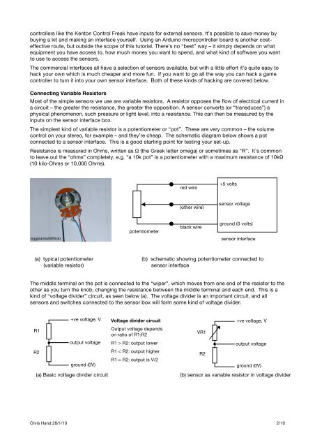
controllers like the Kenton Control Freak have inputs for external sensors. It’s possible to save money bybuying a kit and making an interface yourself. Using an Arduino microcontroller board is another costeffectiveroute, but outside the scope of this tutorial. There’s no “best” way – it simply depends on whatequipment you have access to, how much money you want to spend, and what kind of software you wantto use to access the sensors.The commercial interfaces all have a selection of sensors available, but with a little effort it’s quite easy tohack your own which is much cheaper and more fun. If you want to go all the way you can hack a gamecontroller to turn it into your own sensor interface. Both of these kinds of hacking are covered below.Connecting Variable ResistorsMost of the simple sensors we use are variable resistors. A resistor opposes the flow of electrical current ina circuit – the greater the resistance, the greater the opposition. A sensor converts (or “transduces”) aphysical phenomenon, such pressure or light level, into a resistance. This can then be measured by theinputs on the sensor interface box.The simplest kind of variable resistor is a potentiometer or “pot”. These are very common – the volumecontrol on your stereo, for example – and they’re cheap. The schematic diagram below shows a potconnected to a sensor interface. This is a good starting point for testing your set-up.Resistance is measured in Ohms, written as Ω (the Greek letter omega) or sometimes as “R”. It’s commonto leave out the “ohms” completely, e.g. “a 10k pot” is a potentiometer with a maximum resistance of 10kΩ(10 kilo-Ohms or 10,000 Ohms).red wire+5 volts(other wire)sensor voltageeggplantia5@flickrpotentiometerblack wireground (0 volts)sensor interface(a) typical potentiometer(variable resistor)(b) schematic showing potentiometer connected tosensor interfaceThe middle terminal on the pot is connected to the “wiper”, which moves from one end of the resistor to theother as you turn the knob, changing the resistance between the middle terminal and each end. This is akind of “voltage divider” circuit, as seen below (a). The voltage divider is an important circuit, and allsensors and switches connected to the sensor box will form some kind of voltage divider.R1R2+ve voltage, Voutput voltageground (0V)(a) Basic voltage divider circuitVoltage divider circuitOutput voltage dependson ratio of R1:R2R1 > R2: output lowerR1 < R2: output higherR1 = R2: output is V/2+ve voltage, VVR1output voltageR2ground (0V)(b) sensor as variable resistor in voltage dividerChris Hand 28/1/10 2/10
