

Hacking Sensor Interfaces - MSc Sound Design
Hacking Sensor Interfaces - MSc Sound Design
Hacking Sensor Interfaces - MSc Sound Design
- No tags were found...

Create successful ePaper yourself
Turn your PDF publications into a flip-book with our unique Google optimized e-Paper software.
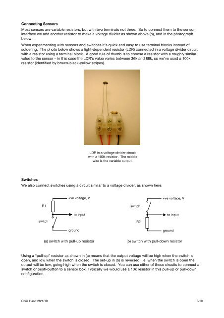
Connecting <strong>Sensor</strong>sMost sensors are variable resistors, but with two terminals not three. So to connect them to the sensorinterface we add another resistor to make a voltage divider as shown above (b), and in the photographbelow.When experimenting with sensors and switches it’s quick and easy to use terminal blocks instead ofsoldering. The photo below shows a light-dependent resistor (LDR) connected in a voltage divider circuitwith a resistor using a terminal block. A good rule of thumb is to choose a resistor with a roughly similarvalue to the sensor – in this case the LDR’s value varies between 36k and 88k, so we’ve used a 100kresistor (identified by brown-black-yellow stripes).LDR in a voltage divider circuitwith a 100k resistor. The middlewire is the variable output.SwitchesWe also connect switches using a circuit similar to a voltage divider, as shown here.+ve voltage, V+ve voltage, VR1switchto inputgroundswitchR2to inputground(a) switch with pull-up resistor(b) switch with pull-down resistorUsing a “pull-up” resistor as shown in (a) means that the output voltage will be high when the switch isopen, and low when the switch is closed. The set-up in (b) is reversed, i.e. when the switch is open theoutput will be low, going high when the switch is closed. You can use either of these circuits to connect aswitch or push-button to a sensor box. Typically we would use a 10k resistor in this pull-up or pull-downconfiguration.Chris Hand 28/1/10 3/10
