

Hacking Sensor Interfaces - MSc Sound Design
Hacking Sensor Interfaces - MSc Sound Design
Hacking Sensor Interfaces - MSc Sound Design
- No tags were found...

You also want an ePaper? Increase the reach of your titles
YUMPU automatically turns print PDFs into web optimized ePapers that Google loves.
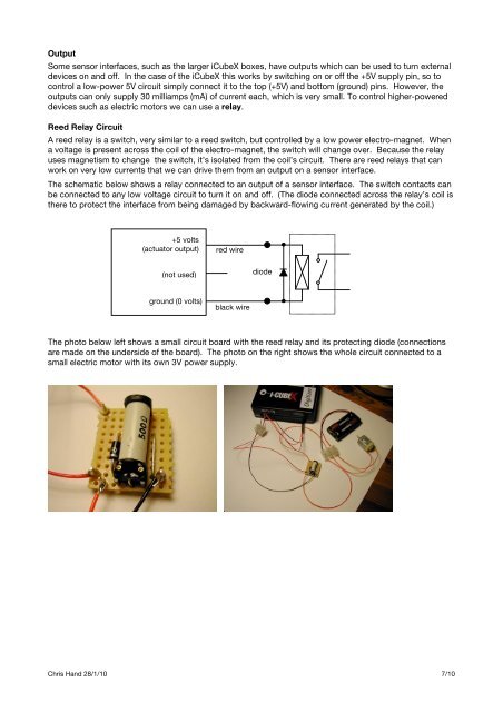
OutputSome sensor interfaces, such as the larger iCubeX boxes, have outputs which can be used to turn externaldevices on and off. In the case of the iCubeX this works by switching on or off the +5V supply pin, so tocontrol a low-power 5V circuit simply connect it to the top (+5V) and bottom (ground) pins. However, theoutputs can only supply 30 milliamps (mA) of current each, which is very small. To control higher-powereddevices such as electric motors we can use a relay.Reed Relay CircuitA reed relay is a switch, very similar to a reed switch, but controlled by a low power electro-magnet. Whena voltage is present across the coil of the electro-magnet, the switch will change over. Because the relayuses magnetism to change the switch, it’s isolated from the coil’s circuit. There are reed relays that canwork on very low currents that we can drive them from an output on a sensor interface.The schematic below shows a relay connected to an output of a sensor interface. The switch contacts canbe connected to any low voltage circuit to turn it on and off. (The diode connected across the relay’s coil isthere to protect the interface from being damaged by backward-flowing current generated by the coil.)+5 volts(actuator output)red wire(not used)diodeground (0 volts)black wireThe photo below left shows a small circuit board with the reed relay and its protecting diode (connectionsare made on the underside of the board). The photo on the right shows the whole circuit connected to asmall electric motor with its own 3V power supply.Chris Hand 28/1/10 7/10
