ECG - Maxim
ECG - Maxim
ECG - Maxim
- No tags were found...

Create successful ePaper yourself
Turn your PDF publications into a flip-book with our unique Google optimized e-Paper software.
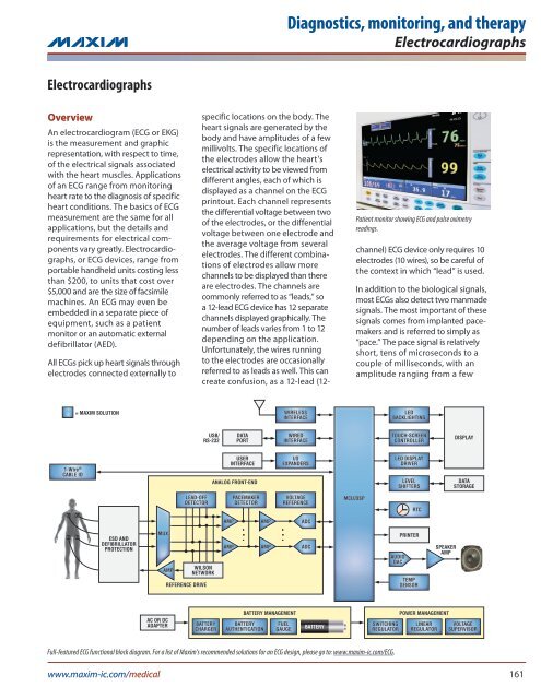
Diagnostics, monitoring, and therapyElectrocardiographsmillivolts to nearly a volt. Often, the<strong>ECG</strong> must detect the presence of apace signal while simultaneouslypreventing it from distorting thesignals from the heart.The second manmade signal is fordetecting “lead-off,” which is whenan electrode is making poor electricalcontact. Many <strong>ECG</strong> devices mustprovide an alert when this poorcontact occurs. Therefore, the <strong>ECG</strong>device generates a signal to measurethe impedance between the electrodeand the body for detecting alead-off occurrence. The measurementmay be AC, DC, or both. Insome <strong>ECG</strong> devices, respiration rateis also detected by analyzing theimpedance from the lead-offmeasurement. Lead-off detection iscontinuous and should not interferewith accurate measurement of theheart signals.FeaturesUnderstanding the required electroniccomponents for an <strong>ECG</strong> iseasier if it is separated into theanalog front-end (AFE), whichdigitizes these signals, and “therest of the system,” which analyzes,displays, stores and transmits thedata. AFEs share the same basicrequirements, but differ in thenumber of leads, fidelity of signal,interference that must be rejected,and so on. The rest of the systemdiffers more radically accordingto whether features are or are notpresent. Typical features include abuilt-in display, the ability to printa hard copy, a radio-frequency (RF)link, and rechargeable batteries.Number of leadsOne of the most obvious featuresis the number of leads. Some <strong>ECG</strong>shave only one lead; the maximumnumber of leads is usually 12. Themost common 12-lead <strong>ECG</strong>s require10 electrodes. Nine of the electrodespick up electrical signalsand the tenth electrode, on theright leg (RL), is electrically drivenby the <strong>ECG</strong> circuit to reduce thecommon-mode voltage. The nineinput electrodes are: left arm (LA),right arm (RA), left leg (LL), and sixprecordial (chest) electrodes (V1through V6). Each lead, or view ofthe heart, is the differential voltagebetween one electrode and anotherelectrode or group of electrodes.When electrodes are grouped, theirvoltage is averaged. RA, LA, andLL are averaged for six of the leads(views) and become one side ofthe differential pair, while V1 to V6are individually used for the otherside of the differential pair. Threeof the leads measure RA, LA, andLL against the average of the othertwo electrodes. The remaining threeleads come from RA, LA, and LLmeasured as individual pairs. Thesix leads based on RA, LA, and LLcontain duplicate information, butdisplay it in different ways. Becausethe information is redundant, it is notnecessary to measure all six leads.Some of the channels can be calculatedby a DSP as it analyzes datafrom the measured channels.AFE capabilities of various <strong>ECG</strong> applicationsCapabilitiesPatientMonitorWhile the 12-lead system describedhere is the most common, it is not theonly one. In addition, 12-lead <strong>ECG</strong>sare capable of operating as a 5-, 3-,or 1-lead systems. The key point hereis the need for a switch matrix andaveraging circuits when more thanone lead is required.Analog front-end (AFE)The primary function of the AFE isto digitize the heart signals. Thisprocess is complicated by the needto reject interference from strong RFsources, pace signals, lead-off signals,common-mode line frequency,signals from other muscles, andelectrical noise. In addition, themillivolt-level <strong>ECG</strong> signal can besitting atop a DC offset that ishundreds of millivolts, with channelto-channelcommon-mode voltagesdiffering by over a volt. The electricalconnections to the patient must notcreate a shock hazard or interferewith other medical equipment thatmay be connected to the patient.The frequency range of interest forthe <strong>ECG</strong> varies somewhat with theapplication, but is usually around0.05Hz to 100Hz.Diagnostic Telemetry Holter AED ConsumerHigh RF immunity U U S S S NMinimum frequency (Hz) 0.05 0.05 0.1 0.1 0.5 0.5<strong>Maxim</strong>um frequency (Hz) 500 500 50 150 40 40ADC sample rate (sps) 1k to 100k 1k to 100k 1024 1024 250+ 250+ADC resolution (bits) 12 to 20 12 to 20 12 to 20 12 to 20 12 10 to 12Right leg drive A A S S N SPace A A U U U SLead-off detection A A U U A SRespiration U S S S S NImpedance S S S S U NDefibrillation A U A U A SA = always, U = usually, S = sometimes, N = never162 <strong>Maxim</strong> Medical Solutions
Diagnostics, monitoring, and therapyElectrocardiographsSecondary functions of the AFEare the detection of pace signals,lead-off detections, respiration rate,and patient impedance. All of this isdone on several channels simultaneouslyor near simultaneously. Inaddition, most <strong>ECG</strong> devices arerequired to recover quickly froma defibrillation event, which cansaturate the front-end and chargecapacitors. This creates a longrecovery time for capacitivelycoupled circuits.AFE architecturesThe AFE architecture has a largeimpact on the features. The bruteforce architecture described belowprovides high fidelity over a widefrequency range due to its highresolution,high-conversion-rate ADC.The lack of capacitive coupling anduse of a DAC for RL drive enables it torecover very quickly from a defibrillationor RF event. Digitizing thepace signal allows pace analysis thatreduces the number of false paceindications and may even detectfaults in the pacemaker or its connections.On the down side, the bruteforce system requires expensivecomponents and uses a great dealof power. In contrast, the minimalAFE features low cost and longbattery life, but little else.Brute force and DSP AFEs. Themeasurement requirements ofan <strong>ECG</strong> can be met by using thebrute force of powerful ADCs tosimultaneously digitize the signalson all nine electrodes to a noisefreeresolution of about 20 bits ata rate of 200ksps. A digital signalprocessor (DSP) can then be usedto calculate the signal for each lead,isolate the pace signal, isolate thelead-off/respiration signals, and filterout unwanted frequencies. The DSPalso calculates values for a digitalto-analogconverter (DAC) drivingthe RL electrode. This AFE methodrequires the analog-to-digital (ADC)channels to be tightly matched andmay require buffering to isolate theADC sampling capacitance fromthe relatively high-impedance electrodes.While this approach maymeet the measurement requirement,it will not meet the cost or powerconsumption requirements of mostapplications.Minimal AFEs. At the other end ofthe AFE features spectrum is the1-lead, consumer-grade <strong>ECG</strong>. TheAFE circuit of this device capacitivelycouples the input signalsto a lowpass differential amplifierthat is followed by a 10-bit, 120spsADC. Capacitively coupling theinputs eliminates DC-offset issues,and lowpass filtering removes thepace signal. There is no commonmodevoltage, because the device isbattery powered and has only onechannel.Typical <strong>ECG</strong> AFEs. The circuitsin most <strong>ECG</strong> devices lie betweenthe above two extremes.Instrumentation amplifiers (IAs) areused to reduce the common-modevoltage, eliminate common-modenoise such as line frequency, andprovide a buffer for the ADC’ssampling capacitance. Filters afterthe IA remove the pace and lead-offsignals before the heart signals aredigitized by the ADC. In some cases,the heart signal and its DC offset aredirectly digitized by a high-resolutionADC. In other cases, highpassfiltering or DACs are used to removethe DC offset so that the heart signalcan be amplified and digitized by alower resolution ADC, typically 12bits. A separate ADC can be usedfor each lead, or one ADC can bemultiplexed to digitize multipleleads. Multiplexing the ADC cancause a slight time skew betweenchannels. How objectionable thisskew is depends on the application.If pace detection is needed, the pacesignal is picked off by a highpassfilter, amplified, and detected by acomparator circuit.APACEDETECTIONAPACEDETECTIONNARROWBANDPASSFILTERALEAD-OFFDETECTIONPGALOWPASSFILTER16- TO24-BITADCPGABANDPASSFILTERA12-BITADCMUXLEAD-OFFSYNCHRONOUSDETECTIONMUXΣn-AΣn-AAVERAGERL DRIVEAVERAGERL DRIVELEAD-OFFSIGNALDC-coupled, high-resolution ADCAC-coupled ADCwww.maxim-ic.com/medical 163
Diagnostics, monitoring, and therapyElectrocardiographsTypes of <strong>ECG</strong> equipmentTelemetry devices<strong>ECG</strong> telemetry systems are usedto continuously monitor ambulatorypatients in a clinical setting.They consist of an RF-equipped<strong>ECG</strong> measurement unit worn by thepatient and a central RF receivingstation that collects and analyzesthe data from many patients. Sometelemetry systems provide additionaldata such as blood-oxygen levels.The data is used to verify or alter theeffectiveness of treatments and towarn of impending problems.Many telemetry systems are limitedto 5 leads, as full 12-lead <strong>ECG</strong>s makeit difficult for patients to be ambulatory.Patients typically use the devicecontinually for a couple of days.Disposable batteries are frequentlyused in these devices. Other <strong>ECG</strong>sare also capable of telemetry, but theterm “<strong>ECG</strong> telemetry” refers specificallyto the mobile units worn in ahospital that transmit data to a localreceiving station. Key considerationsfor telemetry system designs are lowpower, low noise, and small size.Holter monitorsThe name Holter comes from Dr.Norman Holter who invented mobilemonitors for collecting data that islater uploaded to another systemfor analysis. Unlike a telemetry unit,these monitors do not require acentral receiving station and canbe used at home, outdoors, or justabout anywhere. Five leads arefrequently the maximum for a Holter<strong>ECG</strong> monitor, since being ambulatoryis difficult with a full 12-lead <strong>ECG</strong>.Data is most commonly retrievedfrom the monitor by removing thememory card; however, USB andother methods are also used. Mostpatients need only to be monitoredfor a day or two. Special long-termmonitors are used for patientsinvolved in drug studies—they areused by a single patient for a year ormore. Principal concerns for Holter<strong>ECG</strong> monitor designs are low power,low noise, and small size.Consumer <strong>ECG</strong>sThese low-end <strong>ECG</strong>s easily fit ina hand and are used by people totake their own <strong>ECG</strong> test at home.The device stores the data, and alsodisplays it on a built-in screen. This datacan be transferred to a computeror sent through phone lines to ahealthcare provider. Some units havemultiple electrodes on wires, whileothers have two electrodes builtinto the case. Electrodes in the casecan be pressed against the chest,or one hand can be placed on eachelectrode. The resulting <strong>ECG</strong> may notbe the best quality, but it is a way forpeople to monitor themselves and tocapture data about their heart whilethey are experiencing an abnormalevent. Focal issues for consumer <strong>ECG</strong>designs are low cost and small size.Automatic external defibrillators(AEDs)Intended for emergency use by theuntrained public, these devices arefrequently seen in public places suchas shopping malls, gyms, and offices.= MAXIM SOLUTIONWIRELESSINTERFACELEDBACKLIGHTINGDISPLAYCABLE AND PADASSEMBLY1-WireCABLE IDELECTRODESESD AND DEFIBRILLATORPROTECTIONUSB/RS-232ON BOARD/REMOVABLEDATAPORTDATASTORAGEANALOG FRONT-ENDPATIENTIMPEDANCEWIREDINTERFACELEVELSHIFTERSVOLTAGEREFERENCEMCU/DSPTOUCH-SCREENCONTROLLERKEYBOARDSCANNERWATCHDOGTIMERUSERINTERFACELINEPROTECTIONAMPAMPADCRTCCOIN CELLDEFIBRILLATORPADSHIGH-VOLTAGEDISCHARGEHIGH-VOLTAGECONTROLMIC PREAMPSPEAKER AMPAUDIOCODECAC OR DCADAPTERBATTERYCHARGERBATTERY MANAGEMENTBATTERYPROTECTIONFUELGAUGEBATTERYSWITCHINGREGULATORPOWER MANAGEMENTLINEARREGULATORVOLTAGESUPERVISORFunctional block diagram for an AED device. For a list of <strong>Maxim</strong>’s recommended solutions for an AED design, please go to: www.maxim-ic.com/<strong>ECG</strong>.164 <strong>Maxim</strong> Medical Solutions
Diagnostics, monitoring, and therapyElectrocardiographsThey are used immediately after, orduring, a heart attack to jump-startthe heart and restore its naturalrhythm by delivering a high-energyelectric pulse to the chest. This pulsecan also kill if delivered at the wrongtime; <strong>ECG</strong> functionality is needed toensure that this does not happen.AEDs typically have one lead andpick up the heart signal through thesame pair of electrodes that deliverthe high-energy pulse to the chest.An AED could sit for months or yearswithout use, and then be used byuntrained personnel who are notlikely to recognize a problem if oneexisted. When the system is needed,it must turn on, do a thorough selfcheckto verify that everything isworking perfectly, and then operatefor a relatively short period of time.All of the <strong>ECG</strong> data, as well as thedefibrillation information, must berecorded for later analysis. Using adefective AED could do more harmthan good. Therefore, reliability andself-diagnostics are essential considerationsfor AED designs.Diagnostic <strong>ECG</strong>sThese machines are used in hospitalsand doctors’ offices to perform highquality<strong>ECG</strong> tests. They are capable ofperforming a full 12-lead <strong>ECG</strong> test andcreating a hard-copy printout. Theseunits use a high-performance AFE thattypically has options for gain adjustmentand selection of various filtersto improve the quality of the <strong>ECG</strong>measurements. Being larger and lessportable, these machines have roomfor more features, such as built-inprinters, multiple communicationports, and large display screens.These devices are line powered,but usually include a rechargeablebackup battery. Key considerationsfor diagnostic <strong>ECG</strong> designers arelow noise, interference rejection,and flexibility.Patient monitorsThese machines monitor vitalsigns (pulse rate, respiration rate,blood pressure, and temperature). Inaddition, they may include <strong>ECG</strong> functionality,as well as monitor bloodoxygen and carbon dioxide levels.Integrating all of these functionsinto one unit helps unclutter theoperating room and simplifies theprocess of moving the patient fromroom to room without disconnectingthe monitoring equipment.The AFE used for patient monitors issimilar to the AFE used in a diagnostic<strong>ECG</strong>, but must meet RF-rejectionrequirements—these machines areused during surgery and can receivestrong RF signals from electrocauteryknives and argon plasma coagulation(APC) equipment. Rapid recovery froma defibrillation event is also essential.Patient monitors are line powered buthave battery backup, which makespower consumption an importantissue. The cases must be splash proofand easily cleanable. This precludescooling vents, thereby making powerdissipation a consideration. Alongwith power consumption and dissipation,key considerations for patientmonitor designs are RF immunity andlow noise.Common features of various <strong>ECG</strong> applicationsFeatures Telemetry Holter Consumer AED Diagnostic Patient MonitorPowerLine N N N N A ARechargeable S S S S U ADisposable U U U U S SCommunicationRF A S S S S SRS-232/RS-485 N S S S S SEthernet S S S S S SUSB N S S S S SModem N S S S S SData card N U S S S SGraphic display S U A S S APrinter N N N N A SA = always, U = usually, S = sometimes, N = neverwww.maxim-ic.com/<strong>ECG</strong>www.maxim-ic.com/medical 165
Diagnostics, monitoring, and therapyElectrocardiographsZero-drift, low input offset-voltage instrumentation amplifiers save space and costMAX4208/MAX4209The MAX4208/MAX4209 are precision, CMOS-input instrumentationamplifiers that combine a patented spread-spectrum choppingtechnique* with a novel, also patented, indirect current-feedbackarchitecture.** This continuous, self-correcting, autozeroing andchopping technique reduces input offset voltage to just 20µV (max),while minimizing drift over temperature and time.The indirect current-feedback architecture extends the inputcommon-mode voltage range of these amplifiers to below ground,unlike amplifiers using the three-op-amp type of architecture. Thisfeature allows the instrumentation amplifiers to operate froma single-supply voltage rail, eliminating the need for a negativevoltage rail, thus reducing space, power, and cost. Also unlike threeop-ampinstrumentation amplifiers, an internal REF buffer allowsthe use of simple resistor-dividers to drive the reference pin. TheMAX4208/MAX4209 are available in a small, 3mm x 5mm, 8-pinµMAX® package and are specified over the -40°C to +125°C temperaturerange.EN-GeniusN E T W O R KProduct of the YearAwarded Product of the Year: MostInnovative Instrumentation Amplifiersby EN-Genius Network in 2008Benefits••Precision signal processing for excellentperformance––Ultra-low 20µV (max) input offsetvoltage––Autozeroing circuitry eliminates 1/f noiseand temperature drift––Low input bias currents due to CMOSinputs••Reduces cost and saves spacewhen compared to three-op-ampimplementations––Operate from a single-supply voltagerail, thereby needing no negativevoltage rail––Uses only simple external resistordividersto drive reference pin due tointernal REF buffer (MAX4208)––Internal matched resistors eliminateneed for precision resistor packs(MAX4209)––Combines the equivalent of fourprecision op amps in a single 3mm x5mm µMAX packageV DDV DDMAX4208AMPOUTMAX4209AMPOUTR2R2IN-FBIN-FBIN+g MG = 1 + R2R1MAX4208 functional diagramV SSg MR2REF+1 REFIN/MODESHDNIN+g MG = 1 + R2R1MAX4209 functional diagramV SSg MR2REF+1 REFIN/MODESHDN*U.S. Patent #6,847,257.**U.S. Patent #6,559,720.www.maxim-ic.com/medical 167
Diagnostics, monitoring, and therapyElectrocardiographsRecommended solutions (continued)Part Description Features BenefitsTouch-screen controllersMAX11800–03MAX11811MAX1233/34Interface ICsI/O expandersLow-power, ultra-small resistive touchscreencontrollers with I 2 C/SPI interface4-wire touch-screen controller withintegrated haptic motor driver±15kV ESD-protected touch-screencontrollers include DAC and keypadcontroller4-wire touch-screen interface; 12-bit SAR ADC; 5:1multiplexer; 1.7V to 3.6V supply voltage; direct andautonomous modes; 1.6mm x 2.1mm WLP; digitalpreprocessing; data tagging and filtering12-bit ADC; I 2 C interface; proximity driver;automatic power-down; direct or autonomous mode4-wire touch-screen interface; 12-bit SAR ADC;10MHz SPI interface; keypad controller; low power(6µA at 1ksps, 0.3µA shutdown current)Small, highly integrated solution reduces designsize and cost; digital processing reduces busloading of applications processorAutonomous mode reduces processor burden;automatic power-down extends battery lifeCombines touch-screen and keypad controllers tosimplify design and save board space; low powerconsumption extends battery lifeMAX73182-wire, 16-bit, I/O port expander withinterrupt and hot-insertion protectionBus timeout; 2.0V to 5.5VMAX7328/29 I 2 C port expanders with 8 I/O ports 2.5V to 5.5V operation; address up to 16 deviceswith 100kHz I 2 C interface; 10µA quiescent currentLock-up free operation improves reliability; lowersupply voltage simplifies designIncreases number of available port pins withoutneeding a more costly µCLogic-level translatorsMAX13030E 6-channel, high-speed logic-level translator 100Mbps (max) data rate; bidirectional; ±15kV HBMESD protection on I/O V CC lines; 2mm x 2mm UCSPMAX13101E 16-channel logic-level translator 20Mbps (max) data rate; bidirectional; ±15kV HBMESD protection on I/O V CC lines; 3mm x 3mm WLPUSB transceiversESD-protected level shifting enables high-speeddata ratesIntegrates level translation with ESD protection in aspace-saving packageMAX3349E USB transceiver with UART multiplexer USB compliant, operates at 12Mbps; integratedESD on D+/D- linesMAX13481E–83E±15kV ESD-protected USB transceivers withexternal/internal pullup resistorsUSB compliant, operates at 12Mbps; integratedESD on D+ and D- lines; 1.6V to 3.6V logic supplyvoltageESD protection increases reliability; USB and UARTshare a connector to save spaceNeeds no interface chip (compatible with lowvoltageASICs and ASSPs), thereby saving spaceand reducing costRS-232 drivers/receiversMAX3221E/23E/43EMAX3224E–27E/44E/45E±15kV ESD-protected, RS-232 transceiverswith AutoShutdown±15kV ESD-protected, 1µA, RS-232transceivers with AutoShutdown Plus1/1, 2/2, and 3/5 driver/receiver options AutoShutdown functionality extends battery lifewithout changes to existing basic input/outputsystem (BIOS) or operating system (OS)1/1, 2/2, and 3/5 driver/receiver options;3.3V or 5V supply voltage options; 1Mbps(MAX3225E/27E/45E)ESD protection increases reliability; small solutioncan be located on main board or in cable; savespower without changes to existing BIOS or OSESD/line protectionMAX3202E/03E/04E/06ELow-capacitance, 2-/3-/4-/6-channel,±15kV ESD-protection arrays5pF input capacitance; 1nA input leakage current;1nA supply current; footprint as small as 1mm x1mmEasily add (and comply with) IEC 61000-4-2 ESDprotection to any designMAX3205E/07E/08ELow-capacitance, 2-/4-/6-channel, ±15kVESD-protection arrays with TVS2pF input capacitance; transient voltage suppressor(TVS)Increase reliability by protecting high-data-rateinterfacesMAX99402.2V to 5.5V, signal-line overvoltageprotectorSmall, 5.3mm 2 SC70; low, 13µA supply current;±4kV (Contact Discharge) IEC 61000-4 ESDprotectionProtects low-voltage circuitry from high-voltagefaults, thereby improving reliability(Continued on next page)170 <strong>Maxim</strong> Medical Solutions
Diagnostics, monitoring, and therapyElectrocardiographsRecommended solutions (continued)Part Description Features BenefitsVoltage supervisors (continued)MAX16056–59Ultra-low-power supervisory ICs withwatchdog timer125nA supply current; capacitor-adjustable timingMAX16060–62 Quad/hex/octal-voltage µP supervisors Fixed and adjustable thresholds and timeouts;margin-enable and tolerance-select inputs;watchdog timerMAX16072–74µP supervisory circuits in chip-scalepackage1mm x 1mm UCSP; ultra-low, 0.7µA supply currentSave power and battery life—use one IC acrossmultiple applications due to adjustable timeoutsBreadth of features and options provides flexibilityto meet many design needsSmall package saves space; low-power operationextends battery lifeTemperature sensorsDS75LVLow-voltage, ±2.0°C accurate digitalthermometer and thermostat±2°C accuracy from -25°C to +100°C; 1.7V to 3.7Voperation; industry-standard pinout and registersIndustry-standard pinout simplifies migration fromLM75 to lower supply voltageDS7505Low-voltage, ±0.5°C accurate digitalthermometer and thermostat±0.5°C accuracy from 0°C to +70°C; 1.7V to 3.7Voperation; industry-standard pinout and registersIndustry-standard pinout allows easy accuracyupgrade and supply-voltage reduction from LM75MAX6612Small, low-power, analog temperaturesensor19.5mV/°C slope; ±3°C accuracy from 0°C to+70°C; SC70 package; 35µA (max) quiescentcurrentSmall, low-power solution saves board space andextends battery lifeWatchdog timersMAX6814 5-pin watchdog timer circuit 4µA operating current; 1.6s timeout; 140mswatchdog output (WDO) pulse period; push-pullactive-low outputMAX6369–74 Pin-selectable watchdog timers Pin-selectable timeout periods and startup delays;disable feature; open-drain or push-pull active-lowoptionsIncreases safety and reliability by monitoring forand alerting the system of software code executionerrorsIncreases safety and reliability by monitoring forand alerting the system of software code executionerrorsWireless transceiversMAX2830MAX28312.4GHz to 2.5GHz RF transceiver with poweramplifier2.4GHz to 2.5GHz, 802.11g RF transceiverwith integrated PAISM band operation; integrates all RF transceivercircuitry; on-chip monolithic filters (Rx and Tx)IEEE ® 802.11g/b compatible; complete RFtransceiver, PA, PLL, and crystal oscillatorMAX2829 Dual-band, 802.11a/b/g RF transceiver Designed specifically for OFDM 802.11a/b/g WLAN;supports 2.4GHz and 5GHz bands; integrates all RFtransceiver circuitryFor a list of <strong>Maxim</strong>’s recommended solutions for an <strong>ECG</strong> design, please go to www.maxim-ic.com/<strong>ECG</strong>.Saves space by eliminating the need for an externalSAW filterHigh level of integration reduces BOM cost andeases implementationHigh level of integration reduces BOM cost andeases implementation172 <strong>Maxim</strong> Medical Solutions