1. Passing Ship Mooring Study
1. Passing Ship Mooring Study
1. Passing Ship Mooring Study
- No tags were found...

Create successful ePaper yourself
Turn your PDF publications into a flip-book with our unique Google optimized e-Paper software.
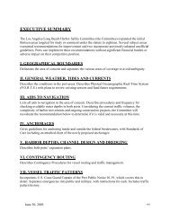
PIER 400 BERTH 408MARINE OIL TERMINAL DEVELOPMENTAT THE PORT OF LOS ANGELESPASSING SHIP MOORING STUDYPrepared for: Pacific Energy Partners, L. P.Prepared by: Moffatt & NicholM&N Job No. 5674-01October, 2005
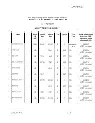
<strong>Passing</strong> <strong>Ship</strong> <strong>Mooring</strong> <strong>Study</strong>Moored VLCC <strong>Passing</strong> Vessel Analysis at Pier 400 Marine Oil Terminal<strong>Passing</strong>Speed (knots)<strong>Passing</strong> Distance(feet)Number of<strong>Mooring</strong> LinesVLCC Draft(feet)Acceptable<strong>Mooring</strong>Case A 5 knots 180 feet 12 7<strong>1.</strong>8 NoCase B 4 knots 180 feet 12 7<strong>1.</strong>8 NoCase C 5 knots 600 feet 12 7<strong>1.</strong>8 NoCase D 4 knots 600 feet 12 7<strong>1.</strong>8 YesCase E 4 knots 500 feet 12 7<strong>1.</strong>8 YesCase F 4 knots 400 feet 12 7<strong>1.</strong>8 YesCase G 4 knots 300 feet 12 7<strong>1.</strong>8 YesCase H 3 knots 180 feet 12 7<strong>1.</strong>8 YesCase I 5 knots 180 feet 14 7<strong>1.</strong>8 NoCase J 5 knots 180 feet 16 7<strong>1.</strong>8 NoCase K 5 knots 180 feet 18 7<strong>1.</strong>8 NoCase L 4 knots 180 feet 12 50.0 YesCase M 4 knots 600 feet 12 50.0 YesOctober 2005ii
<strong>Passing</strong> <strong>Ship</strong> <strong>Mooring</strong> <strong>Study</strong>Figure 5.8 Case H Results.................................................................................................. 20Figure 5.9 Case I Results ................................................................................................... 21Figure 5.10 Case J Results ................................................................................................. 22Figure 5.11 Case K Results................................................................................................ 23Figure 5.12 Case L Results ................................................................................................ 24Figure 5.13 Case M Results ............................................................................................... 25Figure 5.14 Case A, Panamax Tanker................................................................................ 26Figure 5.15 Case A, Aframax Tanker ................................................................................ 27Figure 5.16 Case A, Suezmax Tanker................................................................................ 28Figure 5.17 Case G, 30-knot Wind Beam-on to Vessel..................................................... 29October 2005ii
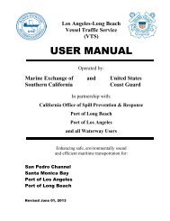
<strong>Passing</strong> <strong>Ship</strong> <strong>Mooring</strong> <strong>Study</strong><strong>1.</strong> INTRODUCTIONThis letter report describes the findings of a ship mooring study for the proposed Pier 400Marine Oil Terminal. The purpose of the study was to examine the loads imposed bypassing vessels at the proposed Pier 400 Marine Oil Terminal. The location of the berthrelative to the navigation channels is shown in Figure <strong>1.</strong><strong>1.</strong> The study purpose is toestablish a preliminary allowable passing speed and distance from the berth to maintainsafe mooring loads and motions. Figure <strong>1.</strong>2 shows the general arrangement of theproposed mooring structures, the position of moored vessels, and proximity to thenavigation channel.Berth 408Angel’s Gate Wind GageFigure <strong>1.</strong>1 Site Map and Proposed Marine Oil Terminal Berth 408 LocationOctober 2005 1
<strong>Passing</strong> <strong>Ship</strong> <strong>Mooring</strong> <strong>Study</strong>Figure <strong>1.</strong>2 Site Map and Proposed Marine Oil Terminal Berth 408 Location2. DESIGN PASSING VESSELThe design passing vessel for the terminal was selected as the largest ship anticipated to passthe terminal. The selected design vessel was the post-panamax containership Susan Maersk.The principal characteristics of the vessel are given in Table 2.<strong>1.</strong>Table 2.1: Post-Panamax Susan Maersk CharacteristicsDeadweight104,676 tonnesLength Overall347 mBeam42.8 mHull Depth24.1 mLoaded (Design) Draft14.5 mAs shown in Figure <strong>1.</strong>2, if a vessel were to travel on the edge of the existing channel, theminimum separation distance between the hull of the passing vessel and the hull of amoored VLCC would be 180 feet (See Figure 2.1).October 2005 2
<strong>Passing</strong> <strong>Ship</strong> <strong>Mooring</strong> <strong>Study</strong>Figure 2.1 Minimum <strong>Passing</strong> DistanceOctober 2005 3
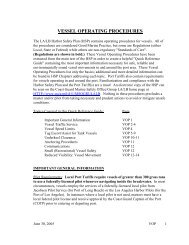
<strong>Passing</strong> <strong>Ship</strong> <strong>Mooring</strong> <strong>Study</strong>3. MOORING SYSTEMFour moored vessels were considered in this study, spanning the range of vessel classesexpected to call at the terminal. The principal dimensions of all four vessels are shown inTable 2. For this analysis, all vessels were analyzed at full draft as this will yield the largestpassing vessel loads. Water depth at the berth is 81 feet MLLW.Table 3.1 Design Vessel CharacteristicsVessel Class PANAMAX AFRAMAX SUEZMAZ VLCCDeadweight, tonnes 69,000 105,000 152,000 307,000Length Overall, Feet 726.2 800.5 883.2 1092.2Length Between Perpendiculars, Feet 695.4 764.4 846.5 1049.6Moulded Breadth, Feet 118.1 137.8 150.0 197.1Moulded Depth, Feet 63.0 70.0 80.0 9<strong>1.</strong>2Displaced Volume Loaded, Feet 3 2,697,451 4,315,417 5,857,079 12,406,750Displaced Volume Ballast, Feet 3 1,267,811 1,958,516 2,239,444 5,052,930Draft Loaded, Feet 4<strong>1.</strong>1 48.6 57.4 7<strong>1.</strong>8Draft Ballast, Feet 19.3 23.0 23.6 3<strong>1.</strong>8Projected Side Area Loaded, Feet 2 18,870 20,957 25,131 27,412Projected Side Area Ballast, Feet 2 33,997 39,568 53,426 69,542Projected Front Area Loaded, Feet 2 5,949 7,728 8,962 12,792Projected Front Area Ballast, Feet 2 8,521 10,753 13,989 20,688Table 3.2 lists the mooring equipment of each design vessel. The ship mooring system iscomprised of mooring lines (i.e., wire ropes with nylon tails) and buckling “cell-type”fenders. The allowable safe working load (SWL) in the mooring lines was set at 55% of theminimum breaking load (MBL). The allowable working load in the fenders was the ratedreaction at maximum deflection (55%). The mooring line SWL is 75 tons. The same linesand fenders were used for each vessel size. It should be noted that a line pretension of 10%of the line MBL (11 tonnes) was used in all simulations. This is an important assumption asit implies that this pretension will be maintained while vessels occupy the berth.October 2005 4
<strong>Passing</strong> <strong>Ship</strong> <strong>Mooring</strong> <strong>Study</strong>Figure 3.3 Moored VLCC, 16 LinesFigure 3.4 Moored VLCC, 18 LinesOctober 2005 6
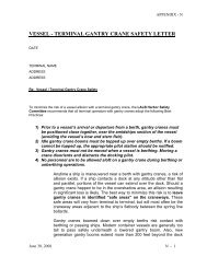
<strong>Passing</strong> <strong>Ship</strong> <strong>Mooring</strong> <strong>Study</strong>4. PASSING SHIP HYDRODYNAMIC LOADS<strong>Passing</strong> ships traveling at high speed and/or proximate to moored vessels will impose largeforces and moments on the moored vessel. These forces can be sufficiently large to partmooring lines or produce large vessel motions. A number of references have emphasizedmethods for computation of the hydrodynamic forces imposed on the moored vessels (e.g.,Seelig, W. (2001), “<strong>Passing</strong> <strong>Ship</strong> Effects on Moored <strong>Ship</strong>s”, Naval Facilities EngineeringCenter, Technical Report TR-6027-DCN and many others). The typical problem of a beamto beam passing scenario is illustrated in Figure 4.<strong>1.</strong>Figure 4.1 <strong>Passing</strong> <strong>Ship</strong> Geometry<strong>Passing</strong>Velocity+F X+M Z+F Y.<strong>Ship</strong> 2(Moving)<strong>Ship</strong> 1(Moored)October 2005 7
<strong>Passing</strong> <strong>Ship</strong> <strong>Mooring</strong> <strong>Study</strong>The passing ship imposes a longitudinal and lateral force as well as a moment on themoored vessel. Typical results are shown in Figure 4.2 and demonstrate that a relativelylarge, but transient load is experienced by the moored vessel. The forces on the mooredvessel are dependant on the distance to the passing vessel, the speed of the passing vessel,the underkeel clearance of both vessels, and the displacement of the two ships. The methodof calculation used in this report is based on the theoretical predictions developed by Wang(1977). Seelig (2001) and Kriebel (2005) modified the theoretical values to includecorrections for shallow water effects based on physical model studies.Figure 4.2 Typical Results for a Beam to Beam <strong>Passing</strong><strong>1.</strong>0Fx0.8FyLVX/LDIMENSIONLESS APPLIED FORCE & MOMENT0.60.40.20.0-0.2-0.4-0.6-0.8Mz (ft-kips)-<strong>1.</strong>0-2.0 -<strong>1.</strong>5 -<strong>1.</strong>0 -0.5 0.0 0.5 <strong>1.</strong>0 <strong>1.</strong>5 2.0X/LDIMENSIONLESS DISTANCE (X/L)Figure 4.3 presents the forces predicted on the moored VLCC by the design passing vesselat a speed of 5 knots and a side-to-side separation of 180 feet. It should be noted that theforces presented in Figure 5 represent the total forces and moment imposed on the mooredship hull. <strong>Mooring</strong> line/fender forces and ship motions are developed from the dynamicmooring analysis presented in the following section.At Pier 400, the closest line of approach to the moored tanker is when vessels are passingparallel to the berth. More oblique angles will result in a vessel track further from themoored tanker. The side-to-side passing analysis, therefore, represents a conservativescenario for assessing the terminal vulnerability to passing effects.October 2005 8
<strong>Passing</strong> <strong>Ship</strong> <strong>Mooring</strong> <strong>Study</strong>Figure 4.3 <strong>Passing</strong> <strong>Ship</strong> Forces- 5 knots, 180-foot Separation DistanceLoad (tonne)4003002001000-100-200-300Surge (tonne)Sway (tonne)Yaw (tonne-m)3000020000100000-10000-20000Moment (tonne-m)-400-300000.000 100.000 200.000 300.000 400.000 500.000 600.000seconds5. DYNAMIC MOORING ANALYSISThe above applied hydrodynamic forces are an essential element in examination of passingship problems. To fully examine practical problems, however, it is necessary to conduct adynamic analysis that simulates the dynamic response of a moored vessel to the imposedhydrodynamic forces. The hydrodynamic forces are normally computed assuming themoored vessel hull is rigid. In reality, the moored ship is relatively free to move in responseto the passing ship forces and will be restrained by mooring lines and fenders. The mooredvessel may experience loads less than, equal to, or larger than the imposed passing shipforces depending on all the factors that dictate dynamic response (i.e. ship mass, systemdamping, mooring stiffness, etc.) Given the propensity for vessels to respond dynamicallyin most problems where passing ship problems have been experienced, M&N have foundthat dynamic analysis is imperative for practical applications, rather than static analysis.The passing ship problem was examined using the TERMSIM computer program which is asix degree of freedom time domain model for mooring dynamics. TERMSIM is a fullydynamic time-domain ship mooring analysis program developed by the Maritime ResearchInstitute of the Netherlands (MARIN). The six degree of freedom hydrodynamiccharacteristics of the ship used in the computer model are based on a series of tankerphysical model tests. The wind coefficients are based on the Oil Companies InternationalMarine Forum (OCIMF) recommendations, the generally accepted standard. Both gustingand constant winds can be modeled. For high wind velocities, gusting winds are morerepresentative and tend induce dynamic response in vessels. For this study gusting windswere applied in conjunction with passing ship forces. The nonlinear mooring line stretchOctober 2005 9
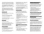
<strong>Passing</strong> <strong>Ship</strong> <strong>Mooring</strong> <strong>Study</strong>are conducted at full draft (with the exception of Cases L and M). Forces induced bypassing vessels increase with submergence of the vessel hull and decreased underkeelclearance; therefore the largest loads on the mooring will occur when the vessel is at fulldraft.The results of the mooring simulation for Case A show that at the minimum passingdistance of 180 feet and a speed of 5 knots, the loads in the forward spring lines exceed theMBL and loads in the forward breasting lines exceed SWL. Manifold excursions are over 2meters in surge and <strong>1.</strong>4 meters in sway. In order to manage the mooring loads, speed mustbe reduced or passing distance increased.When speed is reduced at the same passing distance (Cases B and H) loads are reduced, butloads in the spring lines are still greater than SWL. Increasing passing distance to 600 feetwhile maintaining 5 knots speed (Case C) reduces loads to SWL.Reducing speed to 4 knots at distances of 600, 500, 400, and 300 feet (Cases D-G), keepsline loads well below SWL and manifold motions to less than one meter.Cases I-K re-evaluate Case A with increase number of mooring lines (14, 16, and 18,respectively). All three cases exceed the SWL of the mooring lines. Case 18 is marginal,with loads just exceeding SWL in one line. While deploying more lines improvesperformance, 5-knots speed remains unsafe at the minimum distance.Case L and M show the influence of the hull displacement and underkeel clearance. Byreducing draft to 50 feet, loads are reduced to well below SWL (compare Case L to Case B).When the passing distance is increase to 600-feet, loads and motions are negligible at 50-foot draft.The analysis shows that for moored VLCCs, it is important that speed and distancerestrictions are established. It is recommended that passing vessels be limited to 4 knots orless and that a minimum passing distance of 300 feet be maintained (Case G). Lines shouldbe heaved in to a pretension of approximately 10% MBL and the maximum practicablenumber of lines should be deployed.October 2005 11
<strong>Passing</strong> <strong>Ship</strong> <strong>Mooring</strong> <strong>Study</strong>Figure 5.1 Case A ResultsMoored VLCC at Full Draft12 <strong>Mooring</strong> Lines<strong>Passing</strong> Post-Panamax Container <strong>Ship</strong> @ 5knotsSeparation Distance 180 feet<strong>Mooring</strong> Line Loads160Line Tension (tonnes)1401201008060402001 2 3 4 5 6 7 8 9 10 11 12Line NumberMBLSWLManifold Motion2<strong>1.</strong>5Manifold TrackStart/EndSway (meters)10.50-0.5-3 -2 -1 0 1 2 3Surge (meters)October 2005 13
<strong>Passing</strong> <strong>Ship</strong> <strong>Mooring</strong> <strong>Study</strong>Figure 5.2 Case B ResultsMoored VLCC at Full Draft12 <strong>Mooring</strong> Lines<strong>Passing</strong> Post-Panamax Container <strong>Ship</strong> @ 4knotsSeparation Distance 180 feet<strong>Mooring</strong> Line Loads160Line Tension (tonnes)1401201008060402001 2 3 4 5 6 7 8 9 10 11 12Line NumberMBLSWLManifold Motion2<strong>1.</strong>5Manifold TrackStart/EndSway (meters)10.50-0.5-3 -2 -1 0 1 2 3Surge (meters)October 2005 14
<strong>Passing</strong> <strong>Ship</strong> <strong>Mooring</strong> <strong>Study</strong>Figure 5.3 Case C ResultsMoored VLCC at Full Draft12 <strong>Mooring</strong> Lines<strong>Passing</strong> Post-Panamax Container <strong>Ship</strong> @ 5knotsSeparation Distance 600 feet<strong>Mooring</strong> Line Loads160Line Tension (tonnes)1401201008060402001 2 3 4 5 6 7 8 9 10 11 12Line NumberMBLSWLManifold Motion2<strong>1.</strong>5Manifold TrackStart/EndSway (meters)10.50-0.5-3 -2 -1 0 1 2 3Surge (meters)October 2005 15
<strong>Passing</strong> <strong>Ship</strong> <strong>Mooring</strong> <strong>Study</strong>Figure 5.4 Case D ResultsMoored VLCC at Full Draft12 <strong>Mooring</strong> Lines<strong>Passing</strong> Post-Panamax Container <strong>Ship</strong> @ 4knotsSeparation Distance 600 feet<strong>Mooring</strong> Line Loads160Line Tension (tonnes)1401201008060402001 2 3 4 5 6 7 8 9 10 11 12Line NumberMBLSWLManifold Motion2<strong>1.</strong>5Manifold TrackStart/EndSway (meters)10.50-0.5-3 -2 -1 0 1 2 3Surge (meters)October 2005 16
<strong>Passing</strong> <strong>Ship</strong> <strong>Mooring</strong> <strong>Study</strong>Figure 5.5 Case E ResultsMoored VLCC at Full Draft12 <strong>Mooring</strong> Lines<strong>Passing</strong> Post-Panamax Container <strong>Ship</strong> @ 4knotsSeparation Distance 500 feet<strong>Mooring</strong> Line Loads160Line Tension (tonnes)1401201008060402001 2 3 4 5 6 7 8 9 10 11 12Line NumberMBLSWLManifold Motion2<strong>1.</strong>5Manifold TrackStart/EndSway (meters)10.50-0.5-3 -2 -1 0 1 2 3Surge (meters)October 2005 17
<strong>Passing</strong> <strong>Ship</strong> <strong>Mooring</strong> <strong>Study</strong>Figure 5.6 Case F ResultsMoored VLCC at Full Draft12 <strong>Mooring</strong> Lines<strong>Passing</strong> Post-Panamax Container <strong>Ship</strong> @ 4knotsSeparation Distance 400 feet<strong>Mooring</strong> Line Loads160Line Tension (tonnes)1401201008060402001 2 3 4 5 6 7 8 9 10 11 12Line NumberMBLSWLManifold Motion2<strong>1.</strong>5Manifold TrackStart/EndSway (meters)10.50-0.5-3 -2 -1 0 1 2 3Surge (meters)October 2005 18
<strong>Passing</strong> <strong>Ship</strong> <strong>Mooring</strong> <strong>Study</strong>Figure 5.7 Case G ResultsMoored VLCC at Full Draft12 <strong>Mooring</strong> Lines<strong>Passing</strong> Post-Panamax Container <strong>Ship</strong> @ 4knotsSeparation Distance 300 feet<strong>Mooring</strong> Line Loads160Line Tension (tonnes)1401201008060402001 2 3 4 5 6 7 8 9 10 11 12Line NumberMBLSWLManifold Motion2<strong>1.</strong>5Manifold TrackStart/EndSway (meters)10.50-0.5-3 -2 -1 0 1 2 3Surge (meters)October 2005 19
<strong>Passing</strong> <strong>Ship</strong> <strong>Mooring</strong> <strong>Study</strong>Figure 5.8 Case H ResultsMoored VLCC at Full Draft12 <strong>Mooring</strong> Lines<strong>Passing</strong> Post-Panamax Container <strong>Ship</strong> @ 3knotsSeparation Distance 180 feet<strong>Mooring</strong> Line Loads160Line Tension (tonnes)1401201008060402001 2 3 4 5 6 7 8 9 10 11 12Line NumberMBLSWLManifold Motion2<strong>1.</strong>5Manifold TrackStart/EndSway (meters)10.50-0.5-3 -2 -1 0 1 2 3Surge (meters)October 2005 20
<strong>Passing</strong> <strong>Ship</strong> <strong>Mooring</strong> <strong>Study</strong>Figure 5.9 Case I ResultsMoored VLCC at Full Draft14 <strong>Mooring</strong> Lines<strong>Passing</strong> Post-Panamax Container <strong>Ship</strong> @ 5knotsSeparation Distance 180 feetMaximum <strong>Mooring</strong> Line Loads, metric tonnes160Line Tension (tonnes)1401201008060402001 2 3 4 5 6 7 8 9 10 11 12 13 14Line NumberMBLSWLManifold Motion2<strong>1.</strong>5Manifold TrackStart/EndSway (meters)10.50-0.5-3 -2 -1 0 1 2 3Surge (meters)October 2005 21
<strong>Passing</strong> <strong>Ship</strong> <strong>Mooring</strong> <strong>Study</strong>Figure 5.10 Case J ResultsMoored VLCC at Full Draft16 <strong>Mooring</strong> Lines<strong>Passing</strong> Post-Panamax Container <strong>Ship</strong> @ 5knotsSeparation Distance 180 feetMaximum <strong>Mooring</strong> Line Loads, metric tonnes160Line Tension (tonnes)1401201008060402001 2 3 4 5 6 7 8 9 10 11 12 13 14 15 16Line NumberMBLSWLManifold Motion2<strong>1.</strong>5Manifold TrackStart/EndSway (meters)10.50-0.5-3 -2 -1 0 1 2 3Surge (meters)October 2005 22
<strong>Passing</strong> <strong>Ship</strong> <strong>Mooring</strong> <strong>Study</strong>Figure 5.11 Case K ResultsMoored VLCC at Full Draft18 <strong>Mooring</strong> Lines<strong>Passing</strong> Post-Panamax Container <strong>Ship</strong> @ 5knotsSeparation Distance 180 feetMaximum <strong>Mooring</strong> Line Loads, metric tonnes160Line Tension (tonnes)1401201008060402001 2 3 4 5 6 7 8 9 10 11 12 13 14 15 16 17 18Line NumberMBLSWLManifold Motion2<strong>1.</strong>5Manifold TrackStart/EndSway (meters)10.50-0.5-3 -2 -1 0 1 2 3Surge (meters)October 2005 23
<strong>Passing</strong> <strong>Ship</strong> <strong>Mooring</strong> <strong>Study</strong>Figure 5.12 Case L ResultsMoored VLCC at 50-foot Draft12 <strong>Mooring</strong> Lines<strong>Passing</strong> Post-Panamax Container <strong>Ship</strong> @ 4knotsSeparation Distance 180 feetMaximum <strong>Mooring</strong> Line Loads, metric tonnes160Line Tension (tonnes)1401201008060402001 2 3 4 5 6 7 8 9 10 11 12Line NumberMBLSWLManifold Motion2<strong>1.</strong>5Manifold TrackStart/EndSway (meters)10.50-0.5-3 -2 -1 0 1 2 3Surge (meters)October 2005 24
<strong>Passing</strong> <strong>Ship</strong> <strong>Mooring</strong> <strong>Study</strong>Figure 5.13 Case M ResultsMoored VLCC at 50-foot Draft12 <strong>Mooring</strong> Lines<strong>Passing</strong> Post-Panamax Container <strong>Ship</strong> @ 4knotsSeparation Distance 600 feetMaximum <strong>Mooring</strong> Line Loads, metric tonnes160Line Tension (tonnes)1401201008060402001 2 3 4 5 6 7 8 9 10 11 12Line NumberMBLSWLManifold Motion2<strong>1.</strong>5Manifold TrackStart/End1Sway0.50-0.5-3 -2 -1 0 1 2 3SurgeOctober 2005 25
<strong>Passing</strong> <strong>Ship</strong> <strong>Mooring</strong> <strong>Study</strong>Figure 5.14 Case A, Panamax TankerMoored Panamax at Full Draft12 <strong>Mooring</strong> Lines<strong>Passing</strong> Post-Panamax Container <strong>Ship</strong> @ 5knotsSeparation Distance 180 feet<strong>Mooring</strong> Line Loads160Line Tension (tonnes)1401201008060402001 2 3 4 5 6 7 8 9 10 11 12Line NumberMBLSWLManifold Motion2<strong>1.</strong>5Manifold TrackStart/EndSway (meters)10.50-0.5-3 -2 -1 0 1 2 3Surge (meters)October 2005 26
<strong>Passing</strong> <strong>Ship</strong> <strong>Mooring</strong> <strong>Study</strong>Figure 5.15 Case A, Aframax TankerMoored Aframax at Full Draft12 <strong>Mooring</strong> Lines<strong>Passing</strong> Post-Panamax Container <strong>Ship</strong> @ 5knotsSeparation Distance 180 feet<strong>Mooring</strong> Line Loads160Line Tension (tonnes)1401201008060402001 2 3 4 5 6 7 8 9 10 11 12Line NumberMBLSWLManifold Motion2<strong>1.</strong>5Manifold TrackStart/EndSway (meters)10.50-0.5-3 -2 -1 0 1 2 3Surge (meters)October 2005 27
<strong>Passing</strong> <strong>Ship</strong> <strong>Mooring</strong> <strong>Study</strong>Figure 5.16 Case A, Suezmax TankerMoored Suezmax at Full Draft12 <strong>Mooring</strong> Lines<strong>Passing</strong> Post-Panamax Container <strong>Ship</strong> @ 5knotsSeparation Distance 180 feet<strong>Mooring</strong> Line Loads160Line Tension (tonnes)1401201008060402001 2 3 4 5 6 7 8 9 10 11 12Line NumberMBLSWLManifold Motion2<strong>1.</strong>5Manifold TrackStart/EndSway (meters)10.50-0.5-3 -2 -1 0 1 2 3Surge (meters)October 2005 28
<strong>Passing</strong> <strong>Ship</strong> <strong>Mooring</strong> <strong>Study</strong>Figure 5.17 Case G, 30-knot Wind Beam-on to VesselMoored VLCC at Full Draft12 <strong>Mooring</strong> Lines<strong>Passing</strong> Post-Panamax Container <strong>Ship</strong> @ 4knotsSeparation Distance 300 feet<strong>Mooring</strong> Line Loads160Line Tension (tonnes)1401201008060402001 2 3 4 5 6 7 8 9 10 11 12Line NumberMBLSWLOctober 2005 29
<strong>Passing</strong> <strong>Ship</strong> <strong>Mooring</strong> <strong>Study</strong>6. SUMMARY AND CONCLUSIONSThis report summarizes detailed dynamic mooring analyses of the proposed tanker berth atPier 400 as regards the vulnerability of the berth to the effects of passing ships. Theanalyses show that moored tankers (panamax to VLCC classes) and their mooring systemswill be exposed to rather large passing ship forces. While large, these forces aremanageable even for the large vessel size simultaneously exposed to a 30-knot wind,provided speed and distance restrictions are applied at the berth. Critical to the safeoperation of these berths is the maintenance of pretension on all mooring lines. Linesshould be heaved in to the highest achievable pretension and the maximum practical numberof lines should be deployed. Low pretensions or slack lines could result in larger loads andmotions than the vessel’s mooring systems are equipped to handle. It is recommended thatpassing vessels be limited to a speed of 4 knots and a hull-to-hull passing distance of 300feet or greater.7. REFERENCESKriebel, D., 2005, “<strong>Mooring</strong> Loads Due to Parallel <strong>Passing</strong> <strong>Ship</strong>s,” Technical Report, TR-6056-OCN, Naval Facilities Engineering Service Center.Muga, B. and Fang, S., 1975 “<strong>Passing</strong> <strong>Ship</strong> Effects – From Theory and Experiment,” OTC16719, Offshore Technology Conference, ASCE.Seelig, W., 2001, “<strong>Passing</strong> <strong>Ship</strong> Effects on Moored <strong>Ship</strong>s,” Technical Memorandum TM-6027-OCN, Facilities Engineering Service Center.Wang, S., 1975, “ Dynamic Effects of <strong>Ship</strong> Passage on Moored Vessels,” Journal of theWaterways, Harbor and Coastal Division, ASCE.October 2005 30