mission analysis aspects for earth observations missions
mission analysis aspects for earth observations missions
mission analysis aspects for earth observations missions
- No tags were found...

Create successful ePaper yourself
Turn your PDF publications into a flip-book with our unique Google optimized e-Paper software.
® BuscaLegis.ccj.ufsc.brResponsabilidade civil do Estado por atos omissivosAline Marques Leal *SUMÁRIO: Introdução; 1. Responsabilidade Civil do Estado; 1.1 Definição; 1.2 EvoluçãoHistórica; 2. Tipos de Responsabilidade Civil; 2.1. Responsabilidade Objetiva; 2.1.1. DanoMoral; 2.1.2. Excludentes da Responsabilidade; 3. Responsabilidade Civil do Estado poratos omissivos; 3.1. No Direito Positivo Brasileiro; 3.2. O Ato Omissivo gerador deResponsabilidade 4. Conclusão.INTRODUÇAOO objeto do presente estudo é a análise da controvérsia existente na ResponsabilidadeCivil do Estado, enquanto objetiva ou subjetiva.Com relação à aplicação da Teoria Objetiva quando conduta comissiva, a doutrina ejurisprudência são pacíficas a respeito. No entanto, sobre a conduta omissiva há duasposições, uma seguindo os argumentos de Oswaldo Aranha Bandeira de Mello, continuadapor Celso Antônio Bandeira de Mello, que defende que tal responsabilidade tem naturezasubjetiva, restando, portanto, como de natureza objetiva apenas a responsabilidade porcondutas comissivas. A outra, defende a teoria da responsabilidade objetiva tanto para aconduta comissiva como para a omissiva, aplicando-se, para ambas, a norma do artigo 37,parágrafo 6º, da Constituição Federal.Atualmente, essa divergência vem alcançando o Poder Judiciário, causando umentrave no curso dos processos, em razão das discussões sobre qual a natureza jurídica daresponsabilidade do Estado por condutas omissivas que geraram danos.Desta <strong>for</strong>ma, para maior entendimento da responsabilidade civil do Estado porcondutas omissivas deve-se traçar preliminarmente algumas considerações sobre aevolução histórica da responsabilidade civil e seu desenvolvimento, assim como a aplicação
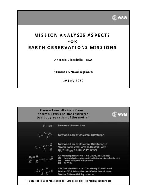
Keplero lawsSummary of Orbital Elements
Right Ascension of the Ascending Node (RAAN):The “Twist” of an OrbitArgument of Perigee:The orientation of the orbit within the orbital plane
True anomaly:The location of a spacecraft in a orbitManoeuvres (1)– For a given gravitational field, the orbital movement of a spacecraft is fullydefined by 6 parameters:– 5 GEOMETRIC ONES FOR DEFINING THE ORBIT– + 1 DYNAMIC FOR DEFINING THE POSITION ON THE ORBITOr, equivalently, by any set of 6 independent parameters, such as ...– THE 3 PARAMETERS DEFINING THE SPACECRAFT POSITION AT A GIVEN TIME– THE 3 PARAMETERS DEFINING THE SPACECRAFT VELOCITY AT THE SAME TIME– Thus, at a given time/position, a propulsive manouvre modifying thespacecraft velocity (in module and direction), also changes is orbit
MANOEUVERS (2)EXAMPLESDelta V Delta VThe number and the intensity of the maneuvres modifying the spacecraftvelocity and thus itsorbit <strong>for</strong> the expected lifetime and beyond may have a significant impact on the mass due to theamount (and the nature) of propellent.Orbit Perturbation: Earth Oblateness (1)– The Earth is an oblate spheroid, lacking the perfect symmetry of a sphere– This lack of symmetry means that the <strong>for</strong>ce of gravity on an orbiting body isnot directed towards the centre of the <strong>earth</strong>– As the gravitational field of a perfectly spherical body depends only on thedistance from its centre, oblateness causes a variation also with latitude: thisis called a zonal variation– The dimensionless parameter which quantifies the major effects of oblatenesson orbits is called J2, the second zonal harmonic: J2 is 1.08263×10 - 3 <strong>for</strong> theEarth– The Earth oblateness generates a perturbing acceleration, so that the orbitequation becomes:
Orbit Perturbation: Earth Oblateness (2)– The vector p has component which are parallel, transversal andnormal to the position vector r describing the orbit à it induce timechanges in the orbital parameters– Neglecting the mathematical details [Prussing and Conway (1993)],one can find that:– The time variation of the right ascension depends only onthe component of the perturbing <strong>for</strong>ce normal to the(instantaneous) orbital plane– The rate of change of the argument of perigee is influencedby all three perturbation componentsTypical Observation Categories <strong>for</strong> EO– Spectrometric Observations– Passive Observations, Microwave– Active Observations, Microwave– Passive Observations, Optical– Active Observations, Optical– Ionosphere and Atmosphere Sounding– Electric and Magnetic Field (DC and VLF) Observations– Gradiometric Observations– The nature and the requirements associated to the <strong>observations</strong>imposes constraints on both the spacecraft and the <strong>mission</strong> design,which drive the complexity of the engineering solutions and thecosts.
From User to the Spacecraft and back to the User again:From needs to data to in<strong>for</strong>mation and knowledgeMain technical requirements <strong>for</strong> <strong>observations</strong>– Geographical Coverage– Frequency of coverage of target areas– Spatial and Spectral resolution– Image Size and Quality– Ground Stations Network available <strong>for</strong> Launch, Early Orbit Phase androutine operations– Specific Illumination Conditions, local time– Data Availability and Reliability– Volume of data produced by the payload– Data Rate– Responsiveness, Acquisition Delay and Latency– End-to-end per<strong>for</strong>mance (It shall be in units that are meaningful to the usernot in units that are meaningful to the space engineer. E.g. Radiometry ofthe instrument is a unit meaningful to the space engineer but sea surfacetemperature is meaningful to the user).
Some System Drivers– Mass and Volume of the Instrument and Spacecraft– Budget constraints <strong>for</strong> manufacturing and operations duringsystem lifetime– Launch Vehicle cost and availability– System reliability and availability– Establishing timely continuity of data– Compatibility between data sets of different generation of<strong>observations</strong> (calibration and validation) towards achieving longterm data sets (e.g. <strong>for</strong> climatology applications)– On-Board autonomy– Magnetic Cleanliness– Space Environment effectsMain Per<strong>for</strong>mance <strong>for</strong> Earth Observation Systems– The system drivers identify the main <strong>mission</strong> parametersinfluencing the achievement of the required per<strong>for</strong>mance vs.cost, risk and schedule <strong>for</strong> both space and ground segment– The system per<strong>for</strong>mance which impact on the orbit designprocess can be summarised in a limited number of peculiarfigures of merit, such as:– Geographical Coverage– Revisit time– Response time– On-ground resolution (spatial and spectral)– Swath
Typical Revisit Time vs Spatial Resolutionsper categories of applicationsRevisit timeyearlyEnd-usercartographymonthlyCartography(telecom,utilities)Marine/CoastalCartography(cadastral)Agriculture,Forestry,Geology,EnvironmentdailyRisk Management,Territory control,Defencefew hourshigh medium lowSpatialresolutionGeographical Coverage and Revisit Time– For a Satellite in Earth Orbit, the time required to complete one revolutionis determined by its radial distance. Spacecraft in Low Earth Orbit (altitude~700-800 km) require about 100 min <strong>for</strong> one orbit– Many Earth Observation Missions require global coverage– Hence the laws of orbital mechanics, in combination with the daily EarthRotation, demand a space-time trade off: a shorter revisit interval impliesless dense spatial coverage– Under such constraint, it may not be possible with only one spacecraft toachieve the simultaneity required <strong>for</strong> fine spatial coverage and shortrevisit intervals– In this cases, a constellation of spacecraft may be the only solution
Influence of Key Mission Parameterson EO System DesignKey ParametersGeographic CoverageResponse TimeRevisit TimeOn Ground ResolutionSwathAffected ParametersNumber of SatellitesPayload Field Of ViewAltitudeOrbitNumber of SateliitesAltitudeNumber and Locations of Ground StationsAccess regionsCommunicationsRe-Scheduling and Processing TimeNumber of SatellitesAltitudeAccess RegionWavelength/Aperture (Optical)Antenna Length/Bandwidth (SAR)AltitudeOff-Nadir Pointing AngleTelescope Field Of View (Optical)Focal Plane Array SizeData RateSatellite Agility (Optical)Antenna Dimension (SAR)Orbital Constraints: Optical and SAR Observations– Low Earth Orbits of interest <strong>for</strong> Optical and SAR have an altitude ranging from~400 km up to ~800 km. This range is imposed by the specific optical and SARpayloads limitations (upper bound) and the drag decay effects (lower bound)– For an optical payload the upper limitation is due to the difficulty ofmaintaining both high resolution and limited instrument dimensionswith the increasing of the altitude (<strong>for</strong> a fixed optical aperture theground spatial resolution linearly decreases with the altitude)– For a SAR payload the upper limitation is due to the difficulty ofmaintaining both high SNR and limited power demand with theincreasing of the altitude (<strong>for</strong> a fixed transmitted power the SNRdecreases with the cube of the altitude)– The exclusion of too low orbit altitudes is due to the drag effects thatmay limit the spacecraft lifetime and/or impose severe constraints onthe propulsion subsystem
Elliptical Orbits– Elliptical orbits in principle may offer coverage advantages in a specificterrestrial hemisphere. In fact, when the orbit is elliptical. the satellite stays<strong>for</strong> a greater period at the apogee crossing, so allowing a major coverage inthe corresponding hemisphere– Because of the altitude range restrictions the maximum apogee altitude thatcan be considered is ~800 km and the minimum perigee altitude is ~400 km– This hypothetical orbit presents very small eccentricity, and consequently,presents also very few advantages in terms of coverage of a specificterrestrial hemisphere, while, on the other hand, presents all environmentalperturbations problems associated to the elliptical orbits– In general the use of elliptical orbits implies non-uni<strong>for</strong>m coverage orsatellite altitude and velocity variations à do not always guarantee adequateinstrument per<strong>for</strong>manceCircular Inclined Orbits– The use of circular inclined orbits has been considered, specially <strong>for</strong> opticalsatellites in military application.– However:– They cover only a limited latitude belt around the equator– The orbit plane rotation induced by the RAAN-rate causes a variationof the illumination conditions of the target sites during the satellitepassage.– For a SAR system these orbits increase the system complexity(thermal control, solar arrays, etc) and costs.– There<strong>for</strong>e also the use of inclined orbits may be attractive <strong>for</strong> EO satellitesaiming at specific latitude <strong>observations</strong> at expenses of limitation inillumination condition and system complexity
Circular Sun-Synchronous Orbits (SSO)– SSO is the orbit which combines altitude and inclination in such a way that thesatellite passes over any given point of the planet's surface at the same local solartime à The orbital plane makes a constant angle with the radial from the sun.– For that to occur, the orbital plane must rotate in inertial space with thesame angular velocity of the <strong>earth</strong> in its orbit around the sun, which is360°per 365.26 days, or 1.991 10 -7 rad/s, or 0.9856° per day (= timederivative of RAAN)– During every orbit, the satellite sees any given swath of the planet under nearly thesame conditions of daylight or darkness day after day and also has a constantperspective on the sun– The use of circular SSO is convenient since it allows:– high latitude accessibility (it results to be quasi polar)– uni<strong>for</strong>m coverage– limited satellite altitude and velocity variations– uni<strong>for</strong>m Sun illumination conditionsSSO properties– In a SSO orbit the ground track pattern is completely defined by thenumber of orbits per day Q.– By indicating with D the repeating cycle (number of days) it ispossible to express Q as:– Q=[Q]+I/D; Note that [ ] = integer part and I is an integernumber (I < D).– By indicating with S the fundamental interval (i.e. the angularequatorial distance between two successive satellite tracks) andwith Si the sub-interval (i.e. the angular equatorial distancebetween trace patterns day by day) we have:– S = 360° /Q and Si = S / D
Selection of I and D <strong>for</strong> the Observation Scheme– The appropriate choice of I and D allows the selection of the desiredobservation scheme– The choice of I=1 or I=D-1 (aka direct orbits or drifting orbits) allows toachieve a good sampling in space but not in time of the pointed targets(e.g. I / D = 15 / 16)– The choice of nI ± 1= D or n (I - 1) ± 1 = D, (aka skipping orbits) allowsto achieve a good sampling in time with a lower spatial resolutionOptical in SSO – Simplified Orbit Selection <strong>for</strong>a single S/C <strong>for</strong> global coverage– The global accessibility is achieved ifthe instrument access at the equatoris greater then the orbit basic subinterval(the angular equatorialdistance between trace patterns dayby day), i.e.: Access Area > Si––All.the accessible sites should be potentially observed during the repeatcycle at least once time with a quasi-nadir observation geometry (i.e. lowoff-nadir looking angles) in order to reach the maximum per<strong>for</strong>mance(minimum spatial resolution, minimum image degradation due to the offnadirobservation)– High repeat cycle length permits to implement incidence angle diversity àThe higher is the repeat cycle length (D) and the lower is the extension ofthe basic sub-interval (Si), allowing the optical instrument to acquire thesame target more times during the orbit cycle and with different incidenceangles.
Optical in SSO – Simplified Orbit Selection <strong>for</strong>a single S/C <strong>for</strong> global coverage– Incidence angle diversity is importantin observing targets casting shadowsdepending from the sun vector angle.– Multi-spectral acquisition can alsoexploit incidence angle diversity <strong>for</strong>classification tasks à the response ofvegetation in the various bands alsodepends on the sun vector incidence.– Incidence angle diversity can also be exploited by multi-spectralacquisition, <strong>for</strong> classification tasks: in fact the response of vegetation inthe various bands does also depend on the sun vector incidence.– Once that the global coverage criterion is satisfied with one satellite, themaximum revisit time is no greater then the repeat cycle intervalOptical in SSO – Simplified Orbit Selection <strong>for</strong>a single S/C <strong>for</strong> global coverage– On the other hand the selection of an orbit with a repeat cycle interval which exactly fitsthe required revisit period is usually not preferred since, in such way, a certain sitewould be always viewed at the same incidence angle (up to 35° off-nadir, with imagedegradation)– In case of a 2 satellite constellation, the preferred orbit will be a skipping orbit toprovide an acceptable revisit time also in the case of availability of one operationalsatellites, and a repeat cycle sufficiently high in order to provide a quasi-nadirobservation capability of the accessible sites within the orbit cycle– The selection of a candidate orbit with the sub-cycle equal to the required revisit periodand with a longer repeat cycle entails that the global accessibility shall be achieved byone operating satellite within the sub-cycle. This means that the following strongercondition must be verified:Access Area >Sub-Cycle Basic Sub-Interval
Limitations <strong>for</strong> the Acquisition of Optical Image– The spectral observation regions covered by the optical payloads (VIS. IR and UV/Visregions) imply some inherent limitation <strong>for</strong> the image acquisition: they can only sensethe sunlight part of Earth (except <strong>for</strong> IR bounds) so that one half of each orbit is useful<strong>for</strong> imagery yielding– The image acquisition <strong>for</strong> the polar regions during solstices is critical due to the poorillumination condition of the scene: as a result, an optical satellite can only take placesduring, theoretically, less than 40 % of the orbit period in average– The necessity to optimise the illumination condition of the Earth scene drives theselection <strong>for</strong> optical satellites of near-noon sun-synchronous orbits, since these orbitsprovide sufficient and near constant sun illumination of the Earth surface– The cloud cover is known to be in the order of 30% to 70% of the time at all latitudes,except <strong>for</strong> very arid climatic zones: this effect further reduces the useful portion of theorbit period <strong>for</strong> optical satellitesSentinel 2 System – Mission Requirements
Sentinel 2 System – Application RequirementsSentinel -2 – Overall Mission Constraints
Sentinel -2Spectral Bands vs Spatial ResolutionVNIRSWIRVIS NIR SWIRVisibleB1B9B1060 mAerosols Water-vapour CirrusB5 B7 B8aSnow / ice / cloud discrimination20 mVegetationRed-edgeB6B11B1210 mContinuity with SPOT5 multispectral400nmB2 B3 B4 B8600nm800nm1000nm1200nm1400nm1600nm1800nm2000nm2200nm2400nmSpectral bands versus spatial resolutionOrbit Determination ProcessAltitude vs Repeat Cycle Length
Orbit Determination ProcessTrade off (with simulation tools)15°15°300km300kmDefinition of the Orbit– Q=14+3/10 defines entirely the orbit. In fact:– Q=143 orbits per 10 daysà 1 orbit is done in 6041.958 s– `R E=6378 km, µ=398600 km 3 /s 2 , T=6042 s– z = 794 km– J 2= 1.08263×10 -3 , e=0, a=R E+zand dO/dt= 1.991 10 -7 rad/s– Cos(i) = - 0.149143129 à i= 98°.557
Selecting the Local Time #1– Based on the limitation in the SZA (75 degrees at maximum), it is possibleto determine the more adequate LTAN or LTDN <strong>for</strong> proper observation overEurope. The results show that the LTAN/LTDN that produce a near-nooncondition over Europe are the best options– In order to avoid the sun glint effect, the LTDN of 10:30 and the LTAN of13:30 are good candidates, as they exhibit the same illumination conditions.– Avoiding morning haze suggests using a LT > 10:00– Sun glint is a phenomenon that occurs when the sun reflects off the surfaceof the ocean at the same angle that a satellite sensor is viewing the surface– A cloud coverage <strong>analysis</strong> with real cloud data over Europe from Meteosathas been per<strong>for</strong>med, taking one full year of <strong>observations</strong>– It has been verified with real cloud data that the best times <strong>for</strong> optical<strong>observations</strong> of Europe in terms of cloud coverage are the early times in themorning. In general, the earlier the node crossing time, the higher ourchances to get a clear picture of the surfaceSelecting the Local Time #2– Simulation shows that the orbit with LTDN 10:30 present less cloudcoverage than LTAN 13:30. There<strong>for</strong>e the proposed time <strong>for</strong> the nodewas LTDN 10:30.
Sentinel -2 System descriptionSatellite• Satellite mass: 1200KG• Satellite power consumption: 1400W (1700W at SolarArray level, GaAs triple junction), 87Ah battery• Hydrazine propulsion system (117Kg)• TT&C using S band (64Kb/s up – 2018Kb/s down), withauthenticated/encrypted commands• X band <strong>mission</strong> data distribution (520 Mbits/sec)• Mission data onboard storage: > 2.4 Tbits• Optical Communication Payload• Wheels, magnetometers, magnetorquers, startrackers, coarse sun and <strong>earth</strong> sensors, accurateInertial Measurement Unit and GPSMultiSpectral instrument• Filter based push broom imager (280KG, 1m 3 )• Three mirrors silicon carbide telescope, with dichroicbeam splitter• Focal plane arrays: Si CMOS VNIR detectors, HgCdTeSWIR detectors passively cooled (190K)• Onboard wavelet compression (~1/3)• Integrated video & compression electronics (state ofthe art wavelet compression)• Radiometric resolution 12bits• Radiometric accuracy < 5%Sentinel -2 Data Delivery– Data delivered to 4 core GS within 1-3 hours after acquisition.– X band data downlink with instrument data rate of 490 Mbit/s (after onboard waveletcompression)– Laser Communication through geo terminal (can be operated simultaneously withthe X band subsystem).– 900 Gbyte per day (1000 CDs): cloud-free images will be further processed.Core GroundStations used<strong>for</strong> thesimulation:Kiruna,Svalbard,Maspalomas,Prince Albert
Sentinel -2 ServicesGeneral services: Global carbon, Crop monitoring, Spatial planning(vegetation, urban), Forest monitoring, Water services, Soil erosion,large scale natural or man made disasters, surveillance of infrastructuresThematic services: Sustainable management of developing countries,Nature protection services, support to humanitarian aid, Food securitySAR in SSO – Simplified Orbit Selection #1– SAR payloads work independently of the sun illuminationconditions: this allows the satellite to be injected in orbits whichare unfavourable <strong>for</strong> optical satellites– Moreover, since images can be obtained during the night and inpresence of heavy cloud cover, the SAR satellites can operate <strong>for</strong> agood percentage of the satellite orbit period, spacecraft busresources permitting– The SAR payload is required to operate in multiple modes. Tradeoff between geometric resolution vs swath width and geometricresolution vs radiometric resolution are required.
SAR in SSO – Simplified Orbit Selection #2– The global accessibility is achieved ifthe instrument access at the equatoris greater then the orbit basic subinterval(the angular equatorialdistance between trace patterns dayby day), i.e.: Access Area > SiThis criterion is conservative as it guarantees the accessibility <strong>for</strong>two times during the whole orbit cycle– High repeat cycle length permits to implement incidence anglediversity. In fact, the higher is the repeat cycle length (D) and thelower is the extension of the basic sub-interval (Si). allowing theSAR instrument to acquire the same target more times during theorbit cycle and with different incidence angles.SAR in SSO – Simplified Orbit Selection #3– Once the global coveragecriterion is satisfied, themaximum revisit time is nogreater than the repeat cycleinterval.– Within the set of orbitssatisfying the global coveragecriterion, this would suggestchoice of the orbit with theshorter repeat cycle, but…– …an orbit with a repeat cycle interval which exactly fits the required revisit periodimplies that a certain site would be viewed with the same incidence angle, preventingthe exercise of the multiple incidence angle option– There<strong>for</strong>e, the preferred orbit would be a skipping orbit having a repeat cyclesufficiently small to provide an acceptable revisit time while warranting an effectiverepeat cycle sufficiently high to allow multiple incidence angle imagery
SAR System Design Considerations #1– Requirements on Power and Signal-to-Noise ratio, Resolution,Incidence angle, Swath Width, Wavelength, Polarisation, CalibrationAccuracy and SNR further constraint the design of the SAR System.– Additional constraints are imposed by the available plat<strong>for</strong>mresources and <strong>mission</strong> design such as Payload Mass and Volume,Power, Ephemeris/Attitude Determination Accuracy, AttitudeControl, Downlink Data rate etc– Given the above inputs, one determines the System Specifications,such as System Gain (losses), rms error versus frequency, receivernoise figure, System Stability (gain/phase versus time andtemperature) etc– Final design is the result of an iterative procedureSAR System Design Considerations #2– Assume that the measurable range of target backscatter coefficient (s°)and the wavelength ? are specified by the users.– Assume that Mass and Power Budgets are constrained by the launchvehicle:– Maximum antenna area and the antenna gain G are limited bythe mass– Maximum Radiated Power is limited by the available DC Power– Minimum Noise Temperature is determined by the Earthtemperature (~300 °K) and the receiver noise figure– Slant Range R is determined by the imaging geometry and theplat<strong>for</strong>m altitude– If we consider the single pulse Radar Equation <strong>for</strong> distributed target toderive the SNR (which is a typical and fundamental design requirement),we realise that there are not many degree of freedom left…
SAR System Design Considerations #3⎛SNR = ⎜⎜⎝P ⋅Gt⋅ λ⎞⎟⎛⋅⎜⎠⎞ ⎛⎟⋅⎜( )⎟ 3 44π⋅ R ⋅ F ⎟⎝ k ⋅Tn⋅ Bn⎠ ⎝ 2⋅sinηop⎠ ⎝ La⎠– Available parameters to enhance the SNR:22σ0c ⋅τp⎞ ⎛ ⋅ ⎞⋅ λ R⎟⎜– Increase the Pulse Duration à Increase Average Power Consumption– Decrease the antenna length while increasing the width to keep Gconstant à reduce the swath width and increase the average powerconsumption due to the higher PRF required– Reduce system losses improving the antenna feed system or byinserting T/R modules into the feed to improve the system gain àincrease power consumption and costs– Lowering the altitude produces a significant improvement of SNR àdecrease the swath widthSAR System Design Considerations #4– All the options to improve the SNR and there<strong>for</strong>e the quality of imageryrequires power and resources of the plat<strong>for</strong>m– User per<strong>for</strong>mance specifications, radar system parameters and plat<strong>for</strong>mresources are strongly interlaced– There is no universal algorithm that can optimise the design across thewide range of applications: the priority ranking of the system per<strong>for</strong>manceparameters depends on the data utilisation and consequently on the users.– Final design is usually a compromise between available resources and userneeds: designers can also request a modification in the given requirementsto match available programmatic constraints
Case Study: Sentinel-1 Per<strong>for</strong>mance RequirementsModeAccessAngleSingle LookResolutionSwath WidthPolarisationInterferometricWide SwathWave mode> 25 deg Range 5 m23 degand36.5 degAzimuth 20 mRange 5 mAzimuth 5 m> 250 km HH+HV orVV+VH> 20 x 20 km HH or VVVignettes at100 km intervalsMainmodesStrip Map 20-45 deg. Range 5 mAzimuth 5 mExtra Wide Swath > 20 deg. Range 20 mAzimuth 40 m> 80 km HH+HV orVV+VH> 400 km HH+HV orVV+VHFor All ModesRadiometric accuracy (3 s )Noise Equivalent Sigma ZeroPoint Target Ambiguity RatioDistributed Target Ambiguity Ratio1 dB-22 dB-25 dB-22 dBSentinel-1 SystemSpace Segment– A constellation of two satellites– Nominal lifetime in orbit of 7 years (consumables <strong>for</strong> 12)– Global coverage– Near-Polar Sun-Synchronous dusk-dawn orbit @ 693km.– Repeat Cycle 12 days, 175 orbit (14 + 7/12 orbit per day)– ~60 GByte/orbit, ~ 1 TByte/day– C-Band Synthetic Aperture Radar Payload– Equipped with an Optical Communication Terminal <strong>for</strong> GEO laser linkGround Segment– S-Band station (Kiruna proposed), with a back-up <strong>for</strong> S/Ccontingencies– Downlink currently assumes three X-Band receiving stations– Alternative downlink via EDRS upon service availability
Instrument Accommodation on SpacecraftSAR Electronic Subsystem (SES)SAR Antenna Subsystem (SAS), Aperture : 12.3 m x 0.84 m14 Tiles each with 20 dual polarized resonant waveguide arrays =280 Dual Polarised T/R modulesSentinel-1 Satellite System Sizing and Per<strong>for</strong>manceSatellite FeaturesOverall Launch MassMain Body DimensionsOperational lifetimePropellant lifetimeOperative autonomyAttitude ProfileAttitude accuracy and knowledgeOrbit Knowledge accuracyPropulsionPowerTT&COn-Bard Storage CapacityData Downlink2298 kg (incl. 135 kg prop.)3400 x 1340 x 1340 mm7.25 years12 years96 hPer<strong>for</strong>mance ParametersGeo-Centric and Geodetic, 3 axes stabilized. Nominal Attitude: Right LookingContinuous steering in Yaw, Pitch and RollAccuracy: 0.01° each axis. Knowledge: better than 0.003° each axis10 m (3 sigma) each axis real-time processing. GPS data allow 5 cm in postprocessingon ground.Mono-propellant, 6 (orbit) + 8 (attitude) thrusters5980W SAW generated Power (EOL). 240 Ah Li-Ion battery. @ 65VS-Band, zenith/nadir antennas: 64 kbps U/L and 128/2048 kbps (switchable)D/L TLM Data1410 Gbit @ EOLX-Band (8.025 – 8.400GHz) - 2 x 260Mbps (useful data rate) 8PSK, 4D-TCMSatellite Reliability & Availability Reliability : 0.74 @ 7.25years. Availability :0.983
Summary of the Level 2 productPer<strong>for</strong>mance predictionS1 Level-2 Product Resolution Per<strong>for</strong>mance UnitsSubsidence Rate 5 x 5/20 m2 1.3/1.3 mm/yearLand Cover Classification (2dB contrast )30 x 30 m2 90/75 % correct classificationForest Non-ForestClassification30 x 30 m2 98.6/75 % correct classificationSoil Moisture 100 x 100 m2 0.8/1.2 volume %Flood Mapping 30 x 30 m2 93/79 % correct classificationSnow Cover Classification 30 x 30 m2 80/75 % correct classificationShip Detection 5 x 20 m2 20/40 ship length (m)Sea Surface Wind Speed 100 x 100 m2 0.4/0.8 m/sSea Surface Currents 5 Hz 30/30 cm/sSentinels 1-3: main sensor characteristics
Conclusion–Thank you <strong>for</strong>your patience!!!!