Treater Valves - Home | Kimray Mobile
Treater Valves - Home | Kimray Mobile
Treater Valves - Home | Kimray Mobile
- No tags were found...

Create successful ePaper yourself
Turn your PDF publications into a flip-book with our unique Google optimized e-Paper software.
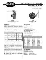
TREATER VALVEModel SWABody, Connections & Pressure RatingsSize2” NPT 125 psig 8.6 bar150 FF 125 psig 8.6 bar3” 125 FF 60 psig 4.1 bar150 FF 125 psig 8.6 bar4” 125 FF 60 psig 4.1 bar150 FF 125 psig 8.6 bar6” 125 FF 60 psig 4.1 bar150 FF 125 psig 8.6 barINSTALLATION:BEFORE INSTALLATION:Be sure you fully understand the application, operation, and connectionof the device before installing.WARNING:Only trained personnel should install or service a control valve.Control valves and other control devices should be installed, operated,and maintained in accordance with international codesand regulations, manufacturer’s instructions, and proven bestpractices.Personal injury, equipment damage, property damage, leakage,or bursting of pressure-containing parts may result if the valveis overpressured or installed where service conditions could exceedthe limits given in the SPECIFICATIONS section.Overpressure protection should also be provided if the valve inletpressure may exceed the safe working pressure of the equipmentdownstream.To avoid injury or damage, install pressure-relieving or pressurelimiting devices to prevent service conditions from exceedingthose limits. Consult the appropriate code, regulations, or standards.Consideration should be given to the potential risk of injury orproperty damage due to escaping fluid. To avoid such risks, installthe regulator in a safe location.1.2.Inspect the openings in the valve for foreign material and clean thepipe lines to remove scale, chips, and debris.Install the valve with the arrow on the body pointing in the directionof flow. The arrow signifies that the device will operateproperly in the direction of flow indicated and willnot necessarily prevent flow in the opposite direction.The flow direction of the <strong>Treater</strong> Valve is down throughthe valve. If conditions indicate the possibilityof backward flow you may wish to install check valves.A person should never stand directly over or in front of avalve when the system is pressurized. Never look directly intoa valve in a pressurized system. The valve could suddenlyopen, blowing gas, dirt, metal particles, or other debris intothe person’s face and eyes.3.Install the valve using good piping practice. For flangedbodies use a suitable gasket between the body and thepipeline flanges. For threaded (NPT) bodies, use TFEtape or pipe thread sealant on external pipe threads.The FLANGE BODIES ARE NOT RATED TO THE ANSI CLASSPRESSURE. Do not install the valve in a system where the workingpressure can exceed valve body rating. CONNECTION RAT-ING CAN BE HIGHER THEN BODY RATING.24.5.Install gas equalizing line to 1/4” connection of drip pot. Do notshare this line with any other equipment.Adjust weight on lever arm, all the way out towards end of leverbar will achieve 4’ of liquid head, all the way in towards Hub assemblywill achieve 2’ of liquid head.