THE VILLIERS CARBURETTOR
THE VILLIERS CARBURETTOR
THE VILLIERS CARBURETTOR
- No tags were found...

You also want an ePaper? Increase the reach of your titles
YUMPU automatically turns print PDFs into web optimized ePapers that Google loves.
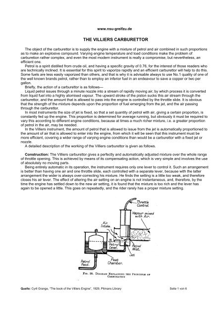
www.nsu-greifzu.de<strong>THE</strong> <strong>VILLIERS</strong> <strong>CARBURETTOR</strong>The object of the carburettor is to supply the engine with a mixture of petrol and air combined in such proportionsas to make an explosive compound. Varying engine temperature and load conditions make the problem ofcarburetion rather complex, and even the most modern instrument is really a compromise, but nevertheless, anefficient one.Petrol is a spirit distilled from crude oil, and having a specific gravity of 0.76, for the interest of those readers whoare technically inclined. It is essential for this spirit to vaporize rapidly and an efficient carburettor will help to do this.Some fuels are less easily vaporized than others, and that is why it is advisable always to use No.1 quality of one ofthe well known brands petrol, rather than to employ an inferior fuel in an endeavour to save a copper or two pergallon.Briefly, the action of a carburettor is as follows—Liquid petrol issues through a minute nozzle into a stream of rapidly moving air; by which process it is convertedfrom liquid fuel into a highly atomised vapour. The upward stroke of the piston sucks this air stream through thecarburettor, and the amount that is allowed to pass into the engine is controlled by the throttle slide. It is obviousthat the strength of the mixture depends upon the proportion of fuel emerging from the jet, and the air passingthrough the carburettor.In most instruments the size of jet is fixed, so that a set quantity of petrol with air, giving a certain proportion, isconstantly fed up the engine. This proportion is determined for average running, but obviously it must be required tovary this according to different engine conditions, because at times a much richer mixture, i.e. a greater proportionof petrol in the air, may be needed.In the Villiers instrument, the amount of petrol that is allowed to issue from the jet is automatically proportioned tothe amount of air that is allowed to enter into the engine, from which it will be seen that this instrument must bemore efficient, covering a wider range of varying engine conditions than would be a carburettor with a fixed jet ornozzle.A detailed description of the working of the Villiers carburettor is given as follows.Construction: The Villiers carburettor gives a perfectly and automatically adjusted mixture over the whole rangeof throttle opening. This is achieved by means of its compensating action, which is very simple and involves the useof absolutely no moving parts.Being entirely automatic in its operation, the instrument requires only one lever to control it. Such an arrangementis better than having one air and one throttle slide, each controlled with a separate lever, because with the latterarrangement the wider is always over-correcting his mixture. He finds the setting is a little too weak, and thereforecloses his air lever. The effect of altering the air setting on an engine is not instantaneous, and, therefore, by thetime the engine has settled down to the new air setting, it is found that the mixture is too rich and the lever hasagain to be opened a little. This goes on repeatedly, and the rider rarely has a proper mixture setting.Quelle: Cyril Grange, “The book of the Villiers Engine”, 1929, Pitmans Library Seite 1 von 6
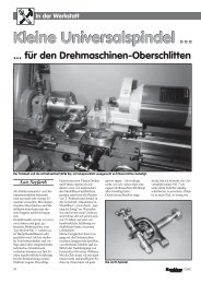
www.nsu-greifzu.deAll this is obviated in the Villiers instrument, because there is only one lever to open and close the throttle, which,at the same time, enlarges or reduces the size of the jet by means of a taper needle attached to and working withthe throttle.An independent adjustment of this taper needle is provided to give a specially rich mixture at times when it isrequired, such as when starting a cold engine. This independent adjustment is provided on same models by meansof a rod (d in Fig. 39A) having a quick-thread in the throttle, which is arranged to raise or lower the needle ¼ inchby one complete turn of the bar. On other models the needle is raised and lowered in the jet by means of aseparate control (D in Fig. 39B) operated from the handlebar. The handlebar lever is marked “ rich” and “ weak “to indicate how the jet size is set.On no account must this top lever be used as an ordinary “air control”. It should remain stationary except whendeliberately wishing to alter the size of the jet.The action of the carburettor is very simple, and reference to Figs. 39(A) and 39(B), showing sectionalarrangements of the two types of carburettors, will make it quite clear. Depressing the float tickler creates a well ofpetrol at a, which, with the throttle open only a little, is drawn into the cylinder at the first kick, so giving very easystarting. The opening and closing of the throttle, as already explained, enlarges and reduces the size of the jet bmeans of the taper needle c. The size of the jet may be independently of the throttle opening, to give a rich mixturewhen starting from cold, the “rich” and “weak” positions being marked on the top disc of the carburettor, or on thehandlebar lever top plate. When the engine is warmed up the needle is again lowered in the jet, to weaken themixture as much as is consistent with good running. The position of the needle will then not require to be alteredagain until the engine is started from cold.When on the road, the automatic compensating action of the carburettor is as follows--Mixture is delivered by the carburettor in two different ways--firstly, by the suction of the engine on the orifice e, and secondly, by the force of the head of petrol through jetb. Since the jet b is below petrol level, petrol is always issuing from it.The suction of the engine on the orifice e draws in a stream of air through the compensating tube f across the topof the jet b where it mixes with and breaks up the petrol, and so issues from there into the main air stream as apartially atomised vapour.If the load on the engine is increased, so reducing the engine speed, as for in stance when hill climbing, thesuction on the orifice e is reduced. This would weaken the mixture but for the fact that the petrol issuing from jet b isconstant, thereby richening the partially atomized vapour coming through e, the combined effect being that theQuelle: Cyril Grange, “The book of the Villiers Engine”, 1929, Pitmans Library Seite 2 von 6
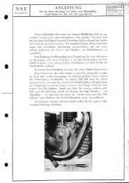
www.nsu-greifzu.derunning on the best setting. If necessary in the case of the single-lever carburettor, the small bar should beunscrewed from the needle rod, and replaced in another hole at right angles to the previous one, so that the needlerod may be turned round further.In the case of the two-lever carburettor there is a screw with a locknut on the body of the handlebar control. Byscrewing this in the mixture is made weaker, and by screwing it out it is made richer. It is very necessary that at alltimes the compensating tubes are clear. Should one be lost, on no account must this be replaced by a screw orplug.To Change the Needle--Single Lever Model. Unscrew the top cap on the body of the carburettor and removethe throttle. Unscrew the bar on the needle rod, and then the needle rod itself. Now by inverting the throttle, theneedle with its small spring will fall out (see Fig. 40). Fit this small spring to the new needle you wish to install,making sure that the small coil of the spring is at the top of the needle, immediately under its head. Place the needlein the throttle, screw in the needle rod, and then replace the throttle in the body of the carburettor, making sure thatthe top disc is located by means of its tongue in the slot on the carburettor body before screwing down the top ring.Tighten the small bar in the needle rod after the correct adjustment hag been obtained, so that this part does notwork loose.Two Lever Model. This differs slightly in construction, and after the throttle is taken out of the carburettor thehexagon in which the cable takes its anchorage must be unscrewed. This will give access to the needle, which isthen changed as on the single-lever model (see Fig. 40A)FIG. 40. REFITTING <strong>THE</strong> TAPER NEEDLE IN <strong>THE</strong> <strong>VILLIERS</strong><strong>CARBURETTOR</strong>FIG. 40(A). SHOWING HOW TO REMOVE <strong>THE</strong> TAPER NEEDLEFROM <strong>THE</strong> THROTTLE OF <strong>THE</strong> TWO-LEVER <strong>CARBURETTOR</strong>Dismantling and Reassembling the Carburettor. The instrument should not be dismantled before firstdetaching it from the engine. Unscrew the top ring and remove the throttle, then turn the carburettor upside downand unscrew the nut at the bottom of the float chamber. Take off the fibre washer, then lift off the cup and the float.This will expose the small fuel needle, which should be carefully lifted out.To remove the centre piece and jet, unscrew the compensating tube or tubes, and the former may then be pulledout. Never unscrew the jet from the centre piece.FIG. 41. FUEL NEEDLE POSITIONQuelle: Cyril Grange, “The book of the Villiers Engine”, 1929, Pitmans Library Seite 4 von 6
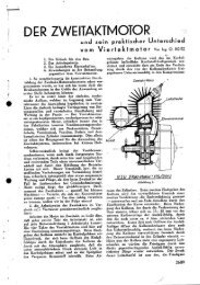
www.nsu-greifzu.deWhen reassembling, clean each part carefully. First place the centre piece in position with the fibre washer underits head, then screw in the compensating tube (or tubes) carefully. Place the fuel needle in position, making surethat the pointed end is inside the carburettor body. Place the float on top of this, and then, after fitting the large fibrewasher, put on the cup, then the small fibre washer, and screw the bottom nut into position. Tighten the latter with aspanner, but do not use too much force.The Needle Rod in the Single-lever Instrument. If this rod looses its tension, and tends to turn round on itsown accord, it should be taken out, and the slotted end of the thread may be opened slightly so as to give the rodmore tension. The best way of doing this is to place a small bar about 1/16 inch in diameter in the slots,approximately 1/8 inch from the end, and then close the ends of the rod together with a pair of pliers (see Fig. 44).FIG. 42. WHEN DISMANTLING <strong>THE</strong> <strong>VILLIERS</strong> <strong>CARBURETTOR</strong>,BEING CAREFUL THAT <strong>THE</strong> FUEL NEEDLE IS NOT LOSTFIG. 43. <strong>THE</strong> COMPENSATING TUBES IN <strong>THE</strong> VILLlERS<strong>CARBURETTOR</strong> MUST BE FREE FROM OBSTRUCTlONWhen detaching the petrol pipe from the tank to the carburettor, this should be handled carefully, and the unionnuts should never be wrenched.Be sure the spanner is a good fit on the outs, and, when undoing the top union, it is advisable to get anotherspanner to hold the hexagon on the tap. so that this does not unscrew with the pipe union.When replacing the petrol pipe, tighten the top and bottom unions together. This is much easier than screwingone up perfectly tight and then endeavouring to get the other nipple into position.FIG. 44. TIGHTENING <strong>THE</strong> NEEDLE RODFIG. 45. <strong>THE</strong> <strong>VILLIERS</strong> AIR CLEANERThe Air Cleaner. Such a fitment as this is always worthwhile on every machine, and if one is not fitted on yourQuelle: Cyril Grange, “The book of the Villiers Engine”, 1929, Pitmans Library Seite 5 von 6
www.nsu-greifzu.demotorcycle, the price is only 4s. 6d., and it is a good investment (see Fig. 45).The air cleaner is fitted on to the air intake side of the carburettor, and prevents dirt and grit passing into theengine. It has a number of vanes on its outer face which give a spinning motion to the air, and a deflector insideflings it outwards, where it is trapped by a lip in the shell of the cleaner. Any particles of dust are ejected here, andthe cleaned air passes without obstruction into the carburettor. There are no moving parts to get out of order, andno gauze which may clog. Consequently, this cleaner requires no attention.If it were possible to see all the grit and dust which is trapped, the rider would get a better idea of the amount offoreign matter which must pass into the engine without a cleaner, and which finds its way into the hearings and willalso damage the cylinder walls, apart from being deposited with the carbon.A Few Carburettor Troubles and their Causes-Constant Flooding. This may be due to a punctured floatwhich allows the petrol to find its way inside, and therefore makes it too heavy, and so causes the float chamber tofill and overflow. Or, to dirt on the seating of the fuel needle, preventing it from closing properly.If the float is punctured, it is as well to replace it, because repairing it with solder may make it too heavy.Another reason for flooding may be the “tickler” jamming down, caused by grit being thrown on to it from the road.To free it, tap gently and pull the tickler up. Clean carefully.Spitting Back. This is the symptom of too weak a mixture, and may be caused by(a) Incorrect setting of the control levers, in which case the jet control must be set further towards “rich”.(b) The fuel needle stuck in its seating, preventing petrol flowing to the carburettor.(c) A choked petrol pipe.(d) Water in the petrol. .N.B. It is impossible for a choked jet to occur on the Villiers carburettor, owing to the needle whichconstantly works inside the jet.(e) The vent hole in the petrol tank choked.There is usually a small hole in the filler cap to allow air to pass into the petrol tank to compensate for the petroldrawn out. If this is choked, a partial vacuum will be created in the tank and obstruct the flow of petrol.Carburettor will Not Shut Off. This may be due to the throttle sticking, probably through mud or grit causing it tobind. This would be prevented if an air cleaner were fitted. Another cause may be a damaged control cable,preventing the inner wire moving freely in the outer cable.Quelle: Cyril Grange, “The book of the Villiers Engine”, 1929, Pitmans Library Seite 6 von 6