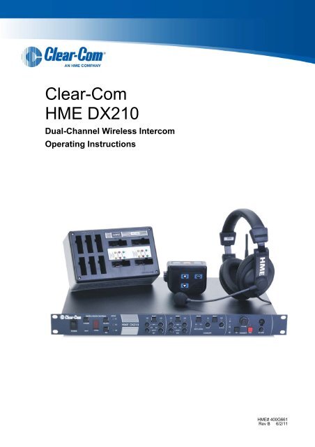
DX210 User Manual - Clear-Com
DX210 User Manual - Clear-Com
DX210 User Manual - Clear-Com
- No tags were found...

You also want an ePaper? Increase the reach of your titles
YUMPU automatically turns print PDFs into web optimized ePapers that Google loves.
Contents1 System Overview ..........................................................................................................................11.1 System <strong>Com</strong>ponents............................................................................................................................ 11.2 Base Station Front Panel ..................................................................................................................... 21.3 Base Station Rear Panel...................................................................................................................... 21.4 Belt Pack – BP210 ...............................................................................................................................31.5 All-In-One Headset – WH210............................................................................................................... 32 System Setup ................................................................................................................................42.1 Battery Charging .................................................................................................................................. 42.1.1 Connect AC Power Supply.............................................................................................................. 42.1.2 Charge Batteries ............................................................................................................................. 52.2 Basic Base Station Setup..................................................................................................................... 62.3 COMMUNICATOR ® Setup and Registration........................................................................................ 72.3.1 Set Up COMMUNICATOR ® s........................................................................................................... 72.3.2 Register COMMUNICATOR ® s ........................................................................................................ 82.3.3 COMMUNICATOR ® Settings........................................................................................................... 92.4 Interfacing with 2-Wire or 4-Wire Intercoms ....................................................................................... 102.5 Interfacing with Auxiliary Audio Equipment ........................................................................................ 112.6 ISO Relay........................................................................................................................................... 123 System Operation .......................................................................................................................133.1 Base Station Operation ...................................................................................................................... 133.1.1 Digital Radio Controls and Indicator Lights ................................................................................... 133.1.2 Local Headset Connector, Controls and Indicator Lights .............................................................. 133.2 COMMUNICATOR ® Operation........................................................................................................... 143.2.1 Power On/Off ................................................................................................................................143.2.2 ISO (Isolate) and IC1, IC2 (Intercom)........................................................................................... 143.2.3 Operating Modes........................................................................................................................... 143.2.4 Volume Up/Down .......................................................................................................................... 143.2.5 Adjusting Microphone Gain ........................................................................................................... 153.2.6 Adjusting BP210 Belt Pack Side Tone .......................................................................................... 153.2.7 Using WH210 All-In-One Headset Lights-Off Mode ...................................................................... 153.2.8 Changing COMMUNICATOR ® Batteries ....................................................................................... 154 Troubleshooting..........................................................................................................................165 Technical Data.............................................................................................................................175.1 BS210 Base Station Specifications.................................................................................................... 175.2 BP210 Belt Pack Specifications ......................................................................................................... 185.3 WH210 All-In-One Headset Specifications......................................................................................... 19Appendix A:COMMUNICATOR ® Indicator Light Functions........................................................20Appendix B: Multiple Base Station Daisy-Chaining ....................................................................21Appendix C:Appendix D:Appendix E:Appendix F:Jumper Settings........................................................................................................22Multiple Base Station Registration..........................................................................23Interference Avoidance through Spectrum Friendly.............................................25Audio Routing Diagram............................................................................................27<strong>Clear</strong>-<strong>Com</strong> HME <strong>DX210</strong> System Guide
1 System OverviewThe <strong>Clear</strong>-<strong>Com</strong> ® HME <strong>DX210</strong> is a 2-channel Digital Wireless Intercom System that supports up to 15COMMUNICATOR ® s per base station, either Belt Packs or All-In-One Headsets, or a combination of thetwo. Using the <strong>DX210</strong> in the 2-channel mode, any 3 of the 15 <strong>Com</strong>municators can transmit at the sametime. In the single-channel mode, any 4 <strong>Com</strong>municators can transmit at the same time. This numbercan be increased by adding up to 3 additional base stations. The <strong>DX210</strong> supports both <strong>Clear</strong>-<strong>Com</strong>and RTS cabled 2-wire intercom systems, and also has 4-wire and auxiliary audio connections.The <strong>DX210</strong> operates in the 2.4GHz band, and has provisions for “Spectrum Friendly” co-existencewith other devices in the same band.1.1 System <strong>Com</strong>ponentsBS210 Base Station:Antennas:110/240 Switching Power Supply:BP210 Belt Pack:Headset:WH210All-In-One Headset:and/orBelt Pack Pouch:Batteries:Battery Charger with 110/240 Switching Power Supply:1 <strong>Clear</strong>-<strong>Com</strong> HME <strong>DX210</strong> System Guide
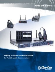
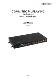
1.2 Base Station Front Panel1 2 3 4 5 6 7 8 9 10 11 12 13 14 15 24 25 26 27 28 29 3016 17 18 19 20 21 22 23 31 32 33 34 35 36 37DIGITAL RADIO CONTROLS1. POWER switch2. RESET button (recessed)3. CLR/BND button4. STATUS display5. REG (registration) button6. UNLATCH button7. RECEIVE indicator lightsIC1 CONTROLS8. IC1 2-W output level adjust9. IC1 2-W input level adjust10. IC1 2-W indicator light11. IC1 AUTO NULL button (recessed)12. IC1 2-W/4-W SELECT button13. IC1 4-W indicator light14. IC1 4-W input level adjust15. IC1 4-W output level adjustIC2 CONTROLS16. IC2 2-W indicator light17. IC2 2-W input level adjust18. IC2 2-W output level adjust19. IC2 2-W/4-W SELECT button20. IC2 AUTO NULL button (recessed)21. IC2 4-W output level adjust22. IC2 4-W input level adjust23. IC2 4-W indicator lightAUXILIARY CONTROLS24. AUX IC1/IC2 INPUT ASSIGN indicators25. AUX INPUT ASSIGN button26. AUX INPUT level adjust27. AUX IN indicator light28. AUX INPUT/OUTPUT SELECT button29. AUX OUT indicator light30. AUX OUTPUT level adjustHEADSET CONTROLS31. HEADSET IC1, IC2 & ISO indicator lights32. HEADSET IC1, IC2 & ISO SELECT button33. HEADSET VOLUME knob34. HEADSET TALK indicator light35. HEADSET TALK On/Off button36. HEADSET MIC LEVEL adjust37. HEADSET cable connector1.3 Base Station Rear Panel38 39 40 41 42 43 44 45 46 47 48 49 50 51 52 5338. ANT (R-TNC)39. PRIMARY/SECONDARY Select Switch40. IC1 4-W RJ-45 Connector41. IC1 2-W XLR-3M Connector42. IC1 2-W XLR-3F Connector43. CLEAR-COM/RTS Select Switch44. IC2 2-W XLR-3F Connector45. IC2 2-W XLR-3M Connector46. IC2 4-W RJ-45 Connector47. SINGLE/DUAL Channel Select Switch48. AUX IN Connector49. AUX OUT Connector50. Relay Connector51. DC Power Connector52. ANT (R-TNC)53. Chassis Grounding Screw2 <strong>Clear</strong>-<strong>Com</strong> HME <strong>DX210</strong> System Guide
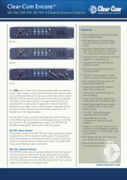
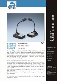
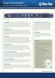
1.4 Belt Pack – BP2103 4 521 6798101. Headset cable connector2. Power/mode lights3. IC2 (Intercom 2) button4. ISO (Isolate) button5. IC1 (Intercom 1) button6. PWR (Power) button7. Volume-up button8. Volume-down button9. Battery10. Battery-release latch1.5 All-In-One Headset – WH2103452619781. Battery2. Battery-release latch3. Power button4. Power/mode lights5. IC1 (Intercom 1) button6. IC2 (Intercom 2) button7. Volume-up button8. Volume-down button9. ISO (Isolate) button3 <strong>Clear</strong>-<strong>Com</strong> HME <strong>DX210</strong> System Guide
2 System SetupThis chapter describes how to set up and configure the <strong>DX210</strong>.Typical equipment connections to the rear panel of the base station2.1 Battery ChargingBefore installing the system, connect the AC power supply to the battery chargerand plug it into an electrical outlet. Charge all the batteries while the otherequipment is being installed. Charging time is about 2.5 hours.2.1.1 Connect AC Power SupplyTo connect the AC power supply to the battery charger:● Connect the AC power supply cable connector to the power connection on the battery charger andturn clockwise to lock in place.● Connect the AC power cord connector to the AC power supply unit.● Connect the AC power cord to an electrical outlet.Power supplycable connectorPower cordconnectorTo electricaloutletBattery Charger AC power supply Power cordThe red lights on the charger will come on briefly, and then the yellow lights will come on and stay on.4 <strong>Clear</strong>-<strong>Com</strong> HME <strong>DX210</strong> System Guide
2.1.2 Charge BatteriesUp to four batteries can be charged in the battery charger at the same time. The battery status lightsnext to each charging port are explained below. Up to six fully charged batteries can be stored in thebattery storage ports.● Insert a battery in each of four charging ports until it clicks in place.● A yellow light next to each charging port stays on while the port is empty.When a battery is in a charging port, a flashing yellow light next to it indicates CHARGE PENDING,which means the battery is too hot. Adjust the room temperature or move the charger to a cooler area.When a battery is in a charging port, a yellow light on steady next to it means CHARGE FAILED.If this happens, follow the instructions on the side of battery charger.● A red CHARGING light next to a battery port stays on while a battery in the port is charging.●A green READY light next to a battery port goes on when a battery in the port is fully charged.● Store fully charged batteries in storage ports.NOTE: Batteries should not be left in charge ports after being fully charged. If a battery is left in acharge port for more than three weeks, the yellow indicator may light up. In this case, it does not indicatea faulty battery.5 <strong>Clear</strong>-<strong>Com</strong> HME <strong>DX210</strong> System Guide
2.2 Basic Base Station SetupThis section describes setup and equipment connections for an individual base station.● Connect the two enclosed antennas to the antenna connectors (#38 and #52) on the rear panel ofthe base station, and turn the sleeves clockwise on the antenna connectors to tighten them securelyin place. Position the antennas at 90° angles from each other.90 o384751 52Base station rear panelAC power cordAC power supply● Plug the connector at the end of the AC power supply cord into the +12-14VDC power connector(#51) on the rear panel of the base station. Turn the locking nut on the cable connector clockwise tosecure it to the base station. Plug the female connector at one end of the AC power cord into thepower supply. Plug the other end of the AC power cord into an electrical outlet.● Set switch #47 for the base station to operate in single or dual channel mode.In single channel mode, all wireless users will be able to hear each other. Up to four users can talksimultaneously.In dual channel mode, there are two separate audio channels enabling two groups of users toindependently communicate with each other. Up to three users can talk simultaneously.NOTE: Any time the mode is changed, the unit must be reset using the reset button or by powercycling for the change to take effect.1Base station front panel 37● If a local headset will be used, plug it into the HEADSET connector (#37) on the front panel of thebase station.NOTE: The connector is keyed, so the headset cable plug can not be inserted in the wrong direction.● Press the POWER switch (# 1) on the front panel to turn on the base station. A red light on the switchshould go on.If you have more than one base station, refer to Appendix D, page 23 for multiple base station registration.6 <strong>Clear</strong>-<strong>Com</strong> HME <strong>DX210</strong> System Guide
2.3 COMMUNICATOR® Setup and RegistrationThe first time you operate the <strong>DX210</strong> system, you must register each <strong>Com</strong>municator (Belt Pack and/orAll-In-One Headset) for use with a specific base station. The base station will then recognize allregistered <strong>Com</strong>municators when their power is on, and will know the difference between them and otherelectronic equipment operating on the same frequencies. If a <strong>Com</strong>municator is added or replaced later,the new one must be registered and the old one remains in memory. A maximum of 15 <strong>Com</strong>municatorscan be registered to a single base station at one time.® s2.3.1 Set Up COMMUNICATOR® sNOTE: If multiple base stations will be used, or if interference is present, such as Wi-Fi interference,refer to Base Station Registration and Interference Avoidance, in Appendix D and E, pages 23 and 25.Before registering them, set up all <strong>Com</strong>municators as follows:Belt Packs ● 1 - Insert a fully charged batteryin each Belt Pack, with themetal contacts on the end ofthe battery inserted first.Press it in until it snaps.12Powerbutton3● 2 - Place each Belt Packin a pouch.● 3 - Plug its headset cableconnector into each Belt Pack.All-In-One Headsets Insert a fully charged battery in each Headset,with the metal contacts on the end of the batteryinserted first. Press it in until it snaps.Powerbutton7 <strong>Clear</strong>-<strong>Com</strong> HME <strong>DX210</strong> System Guide
If you try to register more than 15 <strong>Com</strong>municators:● An F will appear on the STATUS display on the base station and you will hear “Registration failed” inthe headset.● <strong>Clear</strong> all current registrations by pressing the CLR/BND button and the RESET button at the sametime. To press the RESET button, insert a pen or similar pointed object into the RESET hole at thelower-left corner of the base station front panel. Continue holding the CLR/BND button after yourelease the RESET button, until the clear code “c” (lower case) appears on the STATUS display.● Register all active <strong>Com</strong>municators, one at a time. Previously registered <strong>Com</strong>municators must bere-registered.2.3.3 COMMUNICATOR ® SettingsIf you want to set up a <strong>Com</strong>municator with any of the special settings shown below, press and hold thespecified button combinations during or after power up. These settings will remain in memory when the<strong>Com</strong>municators are turned off and on again.For SettingPress & Hold while you Press & Release the Power buttonISO restrict onIC1 buttonISO restrict off IC1 and ISO buttonsHandsfree on selected button(s) IC1 and/or IC2 and/or ISO and ▲ volume up buttonsHandsfree off selected button(s) IC1 and/or IC2 and/or ISO and ▼ volume down buttonsListen-Only mode on▼ volume down buttonListen-Only mode off▲ volume up buttonWH210 only *IC2 buttonAll-In-One Headset “lights-off” mode* NOTE: All-In-One Headsets can be set up with its indicator lights off, to avoid distraction if users are in an areavisible to audience. This setting is not saved when you power off.For Setting With the power already on - - -Increase mic gain (15 steps) Press IC2 while you repeatedly press the ▲ volume up buttonDecrease mic gain (15 steps) Press IC2 while you repeatedly press the ▼ volume down buttonBP210 only *Increase sidetone level (5 steps)Press IC1 while you repeatedly press the ▲ volume up buttonBP210 only *Decrease sidetone level (5 steps)Press IC1 while you repeatedly press the ▼ volume down button* NOTE: There is no sidetone adjustment function for All-In-One Headsets.PowerbuttonNOTE: If you are not connecting a wired intercom, go on to System Operation, section 3, page 13.9 <strong>Clear</strong>-<strong>Com</strong> HME <strong>DX210</strong> System Guide
3 System OperationThis chapter describes how to operate the Base Station and COMMUNICATOR ® (Belt Pack orAll-In-One Headset).3.1 Base Station OperationCOMMUNICATOR ®RegistrationAUX IN Assign andAUX In/Out ControlsPowerSwitchAudio Channel andAuto-Null ControlsLocal HeadsetConnnector & Controls3.1.1 Digital Radio Controls and Indicator Lights● The CLR/BND button, RESET button,STATUS indicator and REG button areused when registering <strong>Com</strong>municators.Refer to <strong>Com</strong>municator registrationprocedure, page 8.● The UNLATCH button is used by the base station operator to unlatch all <strong>Com</strong>municator transmitters.● The RECEIVE IC1, IC2 (Intercoms) and ISO (Isolate) lights indicate whether reception from a<strong>Com</strong>municator is on IC1, IC2 or ISO.3.1.2 Local Headset Connector, Controls and Indicator Lights● The SEL (select) button is used to selectcommunication from the local headset to IC1, IC2,IC1 & IC2, or ISO.● The IC1, IC2, IC1 & IC2, or ISO indicator light will belit for the selection you made.●●●IC1 and IC2 communication will be heard byusers wired into 2-W and 4-W connections.wireless users on the respective channel, as well asISO is heard in both wireless channels, and AUX OUT if activated.NOTE: When the ISO button is pressed, ISO RELAY (#50) is activated.The TALK button is used for communication from the local headset to the selected channel.For open communication, press and release the TALK button quickly to “latch on.” To “latch off,”press and release the button again quickly.For momentary communication, press and hold the TALK button for more than one second. In thismode, the selected channel will remain open only as long as you are pressing the TALK button. TheTALK light indicates the TALK mode is active via the local headset.● Use the VOLUME control to adjust the output to the local headset earpiece.● Use the MIC LEVEL control to adjust the audio level from the local headset microphone.13 <strong>Clear</strong>-<strong>Com</strong> HME <strong>DX210</strong> System Guide
3.2.5 Adjusting Microphone GainSome users talk louder/softer than others. To allow for this, microphone gain adjustment is provided.● To increase microphone gain – While holding down the IC2 button, press the volume-up ▲ button asmany times as necessary to reach the desired level. The microphone gain increase can be monitoredthrough side tone, or preferably by someone else using a <strong>Com</strong>municator or at the base station.● To decrease microphone gain – While holding down the IC2 button, press the volume-down ▼ button asmany times as necessary to reach the desired level. The microphone gain decrease can be monitoredthrough side tone, or preferably by someone else using a <strong>Com</strong>municator or at the base station.NOTE: The mic gain setting will be indicated, in number format, by a voice prompt (typically, HS14 = 5,HS15 = 3, HS16 = 3). You will hear “Maximum” if you attempt to go higher than maximum mic gain. You willhear repeating beeps if you attempt to go lower than minimum mic gain. Microphone gain will be saved inmemory and does not require readjustment each time the power is turned on. (Default setting is 3.)3.2.6 Adjusting BP210 Belt Pack Side Tone● To increase side tone – Press the volume-up ▲ button while holding down the IC1 button in thenormal operating mode.● To decrease side tone – Press the volume-down ▼ button while holding down the IC1 button in thenormal operating mode.NOTE: The side tone setting will be indicated in numbers, by a voice prompt. (Default setting is “Max.”)3.2.7 Using WH210 All-In-One Headset Lights-Off ModeThe Lights-Off mode can be used to avoid audience distraction from the lights on the All-In-One Headsets.● To operate in the Lights-Off mode, with the WH210 power off, press and hold the IC2 button whileyou press the POWER button, and then release both buttons.●To get out of the Lights-Off mode, power the WH210 off and back on again without pressing theIC2 button.NOTE: There is no sidetone adjustment number for the All-In-One Headset.®3.2.8 Changing COMMUNICATOR BatteriesWhen a <strong>Com</strong>municator battery becomes weak, a voice in the earpiece will say “Change battery.”If us ing a Belt Pack , you must remove it from its pouch to access its battery.Battery Battery-releaselatchBattery-releaselatchBatteryBelt Pack battery removalAll-In-One Headset battery removalSlide the arrow-shaped battery release latch in the direction of the arrow. Pull up on the battery near thebattery-release latch and lift the battery out of the unit, or turn the unit over and catch the battery in yourhand.When replacing a battery, place the end of the battery with the metal contacts into the battery holder, inthe same position as the battery you removed. Press the top of the battery carefully into the batteryholder until it snaps in place under the battery-release latch.15 <strong>Clear</strong>-<strong>Com</strong> HME <strong>DX210</strong> System Guide
4 Troubleshooting● Red light on base station power switch does not come on.Be sure the power cords are properly connected to base station, power supply and electrical outlet.● Belt Pack power lights do not turn green and “out of range” is heard in the headset.Be sure your base station power is on. Turn the Belt Pack and base station power on and off. You maybe too far from the base station. The range varies with each location’s layout.● When trying to register, it keeps saying registration failed.Refer to “If registration failed” in section 2.3.2, page 8, and repeat the registration procedure. If “F ”shows up on the STATUS display, it indicates that an attempt has been made to register more than 15Belt Packs. Follow the related instructions in section 2.3.2, page 9.●Others cannot hear me when I talk.Be sure the headset is securely connected to the Belt Pack or base station, and that you are pressingthe IC1, IC2 or ISO button on the Belt Pack, or the TALK button on the base station. Be sure theappropriate IC1, IC2 or ISO setting is selected in the HEADSET section of the base station front panel.● People on the 4-wire intercom cannot hear me or I cannot hear them.Be sure the cables are securely connected and the 4-wire intercom is on. If using a local headset, besure the desired IC setting is selected in the HEADSET section of the base station front panel. If using aBelt Pack or All-In-One Headset, press the desired IC button.® ®● People on the RTS /<strong>Clear</strong>-<strong>Com</strong> systems cannot hear me, or I cannot hear them.Be sure the cables are securely connected and the 2-wire intercom is on. If using the local headset, besure the desired IC setting is selected in the HEADSET section of the base station front panel. If using aBelt Pack or All-In-One Headset, press the desired IC button.● The 2-wire intercom is on and there is a loud squeal whenever I try to talk.This can occur if two or more base stations are daisy-chained without terminating the appropriatechannel. The termination is set by putting JP5 (IC1) and/or JP6 (IC2) in the ON position. This should bedone in only one base station. Refer to Appendix C, page 22 for jumper (JP) locations.● Settings are not retained when the base station power is turned off and on again.The internal battery may be low. Contact your dealer.● 2-W LEDs remain red. No 2-wire power detected.Plug into 2-W power supply. If the lack of powered 2-W system is intentional (such as when using a<strong>Clear</strong>-<strong>Com</strong> MT1, or when daisy-chaining multiple base stations), open the base station cover and setJP1 (IC1) and/or JP2 (IC2) to the ON position. If daisy-chaining, do not forget to also terminate one ofthe base stations by setting JP5 (IC1) and/or JP6 (IC2) to ON. Refer to Appendix C, page 22 for jumper(JP) locations.● Echo on 2-W line.Be sure no wired Belt Packs have open mics and that the line is terminated, and rerun Auto Null.16 <strong>Clear</strong>-<strong>Com</strong> HME <strong>DX210</strong> System Guide
5 Technical Data5.1 BS210 Base Station SpecificationsGENERALChannels:Frequency Range:Frequency Response:Power Requirements:Temperature Range:Size:Weight:# of COMMUNICATOR ® sper Base:4-Wire I/O:2-Wire I/O:Auxiliary Input:Auxiliary Output:Headset Connector:Headset Output:Antenna Type:System Distortion:
5.3 WH210 All-In-One Headset SpecificationsGENERALChannels:2 audio channelsFrequency Range: 2400 MHz – 2483.5 MHzAntenna:InternalFrequency Response: 200 Hz to 3.5 kHzBattery Requirements: 3.6V lithium ionBattery Life:Up to 20 hoursTemperature Range: 32-122°F (0-50°C)Weight:5.7 oz (.16 kg) with batteryMicrophone:ElectretHeadset Output:160mW into 32ΩControls:Power, Volume-up, Volume-down, IC1, IC2, ISOIndicators:Dual-color LED (red/green)<strong>Com</strong>munication Security: 64-bit encryptionSystem Distortion:
Appendix A:COMMUNICATOR ® Indicator Light FunctionsBP210 Belt Pack Indicator Lights:BP210 Condition IC1 Indicator Light IC2 Indicator LightIC1 Idle Steady Green OFFIC1 TX Blinks Green OFFIC2 Idle OFF Steady GreenIC2 TX OFF Blinks GreenISO TX Blinks Green Blinks GreenLow batteryAppropriate channel light Blinks Red when in idle modeWH210 All-In-One Headset Indicator Lights:WH210 Condition Main Indicator Light Boom Indicator LightIC1 Idle Steady Green OffIC1 TX Blinks Green Steady GreenIC2 Idle Steady Red OffIC2 TX Blinks Red Steady GreenISO TXLow batteryBlinks Red or Green(depending on previous Mode)No indicationSteady Red20 <strong>Clear</strong>-<strong>Com</strong> HME <strong>DX210</strong> System Guide
Appendix B:Multiple Base Station Daisy-ChainingTwo or more <strong>DX210</strong> base stations can be “daisy-chained” together with cables connected to the 2-Wconnectors on the rear panels of each base station, following <strong>Clear</strong>-<strong>Com</strong> ® / RTS ® standards, or two basestations (not more) can be “daisy-chained” together with cables connected to the 4-W or AUX connectors.NOTE 1: <strong>DX210</strong> does not provide 2-wire line power, therefore, 2-wire power bypass must be used.RTS ® ModePin 1 = <strong>Com</strong>monPin 2 = Channel 1Pin 3 = Channel 2<strong>Clear</strong>-<strong>Com</strong> ® ModePin 1 = <strong>Com</strong>monPin 2 = N/CPin 3 = AudioNOTE 2: For AUX type daisy-chaining, the cable connectors must be 3-pin XLR.● If using 4-wire connection, use cable with In/Outcrossed, as shown to the right.(An Ethernet crossover cable will not work.)IC In + ─── IC Out +IC In – ─── IC Out –IC Out + ─── IC In +IC Out – ─── IC In –● If using 2-Wire connections, open each base station and set jumpers JP1 (IC1) and/or JP2 (IC2) inall base stations to ON for power detect bypass. Set jumpers JP5 (IC1) and/or JP6 (IC2) in only onebase station per channel for termination. Refer to Appendix C, page 22.● Perform base station registration for each base station. Refer to Appendix D, page 23.21 <strong>Clear</strong>-<strong>Com</strong> HME <strong>DX210</strong> System Guide
Appendix C: Jumper SettingsThe base station has internal jumpers that are used to set ISO broadcast restrict, power detect by-pass,and 2-wire channel termination.Jumper #JP1JP2JP3JP4JP5JP6JP7FunctionChannel 1, 2-wire power detect bypassChannel 2, 2-wire power detect bypassReservedDisable ISO from going out to Belt PacksChannel 1, 2-wire terminationChannel 2, 2-wire terminationReservedISO Broadcast RestrictThis feature prevents ISO communication from being broadcast from one COMMUNICATOR ® to other<strong>Com</strong>municators. Local headset ISO will still be broadcast, and the local headset will still receive ISOcommunication. To enable this feature, set JP4 to ON.Power Detect BypassIn the event the <strong>DX210</strong> base station is connected to a 2-W line which does not contain power (such aswhen multiple base stations are daisy chained), JP1 (IC1) and/or JP2 (IC2) need to be set to ON toenable 2-W interface for the respective channel(s) to come on.WARNING! If no termination is present on the line, enabling this feature will cause feedback inthe headsets.2-Wire Channel TerminationIf termination of the base station is necessary (such as when multiple base stations are daisy chained), setthe JP5 (IC1) and/or JP6 (IC2) jumpers to the ON position on one base station, when connecting multiplebase station together via 2-wire connection. Only one base station should be terminated per channel.22 <strong>Clear</strong>-<strong>Com</strong> HME <strong>DX210</strong> System Guide
Appendix D: Multiple Base Station RegistrationFor multiple base stations to operate in close proximity without interference, they must all be properlyregistered before performing any other setups. After registering each base station, register eachCOMMUNICATOR ® that will be used with that base according instructions in section 2.3.2, page 8.NOTE: If using split-band operation, select the appropriate band prior to base station registration. If adifferent frequency band needs to be selected to avoid interference, the primary base station must beset to this frequency band before base station registration is started.Register each base station and all Belt Packs and/or All-In-One Headsets as follows:● On one of the base stations, ensure that the primary/secondary switch is set to primary. On theothers, ensure that it is set to secondary.NOTE: In split band operation, there can be one primary and up to three secondary base stations ineither band.● Turn the primary base station power on. Register any <strong>Com</strong>municators to be used with the primary basestation, as instructed in section 2.3.2, page 8. Turn each <strong>Com</strong>municator off after registering it.● Power on one secondary base station. The STATUS display will show a double bar, indicating thesecondary base station is ready to be registered.Double barSmall “o”Base station ready to be initializedSmall "o" indicates primary basestation is open for registration● Press the REG (register) b utton on the primary base station. The STATUS display will show a small “o.”● To assign a number to a secondary base station and register it, press the REG button on thesecondary base station. Pressing the button repeatedly causes it to cycle through the numbers 1, 2,and 3. When the desired number appears, stop pressing and wait. While the secondary base stationis registered using the displayed number, the STATUS display will continue showing the secondarynumber selected. When registration of the secondary base station is finished, the display will showone bar, to indicate the secondary has been registered to the primary.Secondary base numberOne barSecondary 2 searching for primarySecondary is initialized to primary● Press the REG button on the primary. The STATUS display will go blank.● Register <strong>Com</strong>municators to the secondary base stations as instructed in section 2.3.2, page 8. Afterregistration, turn off the secondary base station and all <strong>Com</strong>municators.23 <strong>Clear</strong>-<strong>Com</strong> HME <strong>DX210</strong> System Guide
● Repeat these steps for each remaining secondary base station. Use a different number for each.Only the primary base station and the secondary base station you are currently working with shouldhave power on during registration. All other equipment should be off.● After all secondary base stations are registered and COMMUNICATOR ® s are registered, power upall base stations. Press reset on the primary base station and let it recover. Turn on the primary<strong>Com</strong>municators and let them link. Press the reset on each secondary base station one at a time andlet it link to the primary, as indicated by a single bar. Turn on the <strong>Com</strong>municators associated with thesecondary base stations. Do one group at a time until they have all linked. Then do the next group.At this point all base stations and <strong>Com</strong>municators should be powered up and linked, ready for use.● Now proceed with normal system configuration, setting functions and levels as required.● If it becomes necessary to replace a secondary base station, use the procedure above to register thenew secondary with the same number as the old secondary. After registration, you will have toregister any <strong>Com</strong>municators associated with the old secondary to the new secondary base station.● If it becomes necessary to replace a primary base station, follow the above procedure completely.Before registration of the secondary base stations, clear the previous secondary registration asfollows. For each secondary, press the CLR/BND button and the RESET button at the same time.Continue holding the CLR/BND button after you release the RESET button, until the clear code “c”(lower case) appears on the STATUS display. Any <strong>Com</strong>municators associated with the old primarywill have to be registered to the new primary after secondary base station registration. All<strong>Com</strong>municators associated with secondary base stations also have to be registered again.●If the primary base station is shut down or if the primary baseis powered off for more than 30 seconds, all secondary basestations will drop their <strong>Com</strong>municator connections and beginsearching for the primary. If the primary is not found in 30seconds, the secondary will automatically revert to primarymodeoperation and reconnect the <strong>Com</strong>municators. At thispoint the secondary STATUS displays will show three bars.If the primary is turned back on it will be necessary to pressRESET on all secondary base stations to allow them to findand initialize to the primary again. It is therefore important tohave all base stations connected to the same AC circuit toprevent this situation when the system is shut down afterhours and powered up again the next day.Three barsSecondary base stationoperating in primary modewhen no primary base stationis foundNOTE: You cannot register <strong>Com</strong>municators to a base that is set to primary mode, and then switch thebase mode to secondary for registration. Once in secondary mode, the base station cannot recognizethe <strong>Com</strong>municators registered during primary operation. For secondary base stations, the<strong>Com</strong>municators must always be registered after secondary base station registration, with the primarybase station remaining active and the secondary base station displaying one bar.24 <strong>Clear</strong>-<strong>Com</strong> HME <strong>DX210</strong> System Guide
Appendix E: Interference Avoidance throughSpectrum FriendlyInterference, which may be heard in a headset as popping sounds, may occur whenever otherequipment such as Wi-Fi systems or wireless DMX systems, etc. use the same frequency band. Somesystems can be limited to one portion of the band. If so, the <strong>DX210</strong> can be set to the opposite half of the2.4 GHz to 2.48 GHz band. To avoid this type of interference, select the upper or lower part of thefrequency range.CLR/BND buttonSTATUS displayREG button● Turn on the base station power. An “8” will appear on the STATUS display for a few seconds.● After the “8” disappears and the STATUS display is blank (primary base station) or shows a doublebar (secondary base station), press and hold the CLR/BND button and then, while you are stillholding the CLR/BND button, press and hold the REG button and wait until a L, H or A appears, andthen release both buttons.NOTE: Base stations are shipped in the A (default) position.● Press the CLR/BND button to cycle through parts of thefrequency band, (L = Low end, H = High end, and A = All)and stop on the desired setting.● Wait until “c” appears on the display.NOTE: “c” will only appear on the STATUS display if you are setting the frequency band the first time,or you are changing the setting. If you stop at L, H or A that was already set, an “8” will appear for a fewseconds and the STATUS display will become blank.®● Register all COMMUNICATOR s to be used with each base station as instructed in section 2.3.2,page 8.NOTE: If you change a base station’s frequency band setting, you will have to re-register all<strong>Com</strong>municators that were registered to that base station.25 <strong>Clear</strong>-<strong>Com</strong> HME <strong>DX210</strong> System Guide
Spectrum FriendlyAll DX Series wireless intercom systems now feature Spectrum Friendly technology for interference-freeoperation in the increasingly crowded 2.4GHz frequency band. This new technology enables broadcastand theatrical production crews to avoid emerging frequency conflicts by designating the 2.4GHz operatingfrequency range: low-, high-, or full-band. While generally not a problem when separated, multipleapplications and multiple users of the same applications in close proximity can result in additional risk fortrouble-free operation. The new technology further ensures that products do not add interference to thespectrum for other essential wireless services in the vicinity, such as DMX-controlled lighting.Avoiding Wi-Fi InterferenceTo avoid interference with Wi-Fi systems, it is recommended to set the Wi-Fi system to something otherthan channel 6 or 7.Your <strong>DX210</strong> should be set to the high or low band opposite any Wi-Fi frequency range in use.<strong>DX210</strong> Low Band = 2.4000-2.4400 GHz <strong>DX210</strong> High Band = 2.4433-2.4830 GHzChannel 1 2 3 4 5 6 7 8 9 10 11 12 13 14Wi-Fi Frequencies 2.412 2.417 2.422 2.427 2.432 2.437 2.442 2.447 2.452 2.457 2.462 2.467 2.472 2.484 GHz26 <strong>Clear</strong>-<strong>Com</strong> HME <strong>DX210</strong> System Guide
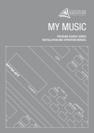
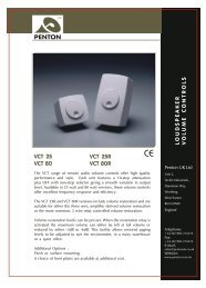
Appendix F: Audio Routing Diagram27 <strong>Clear</strong>-<strong>Com</strong> HME <strong>DX210</strong> System Guide
有 毒 有 害 物 质 或 元 素 表Table of Toxic and Hazardous Substances部 件 名 称Names of PartsBS210 基 站铅Pb有 毒 有 害 物 质 或 元 素Toxic and Hazardous Substances or Elements镉 汞 六 价 铬 多 溴 联 苯Cd Hg Cr6+ PBB多 溴 二 苯 醚PBDETop assembly BS210(G28707-1A1)基 站 电 路 板Audio PCB(G28718-1)收 发 器 电 路 板Front Panel PCB(G28729-1)收 发 器 电 路 板XCVR PCB(G27739-4A1)AC40 电 池 充 电 器AC40(G27368)电 源 器(453G008)X O O O O OX O O O O OX O O O O OX O O O O OX O O O O OX O O O O OCCC P/SO: 表 示 该 有 毒 有 害 物 质 在 该 部 件 所 有 均 质 材 料 中 的 含 量 均 在 SJ/T11363-2006 标 准 规 定 的 限 量 要 求 以 下 。O: Indicates that this toxic or hazardous substance contained in all of the homogeneousmaterials for this part is below the limit requirements in SJ/T11363-2006X: 该 有 毒 有 害 物 质 至 少 在 该 部 件 的 某 一 均 质 材 料 中 的 含 量 超 出 SJ/T11363-2006 标 准 规 定 的 限 量 要 求 。X: Indicates that this toxic or hazardous substance contained in at least one of the homogeneousmaterials used for this part is above the limit requirements in SJ/T11363-2006
有 毒 有 害 物 质 或 元 素 表Table of Toxic and Hazardous Substances部 件 名 称有 毒 有 害 物 质 或 元 素Names of PartsToxic and Hazardous Substances or Elements铅Pb镉Cd汞Hg六 价 铬Cr6+多 溴 联 苯PBB多 溴 二 苯 醚PBDEBP210 对 讲 机Top Assembly BP210(G27830-1A1)X O O O O O对 讲 机 电 路 板XCVR PCB(G27560-1H1)X O O O O OHS15 耳 机HS15/D Headset(306G100-1 /306G101-1)X O O O O O对 讲 机 套Pouch(107G065)电 池Battery(104034)X O O O O OO O O O O OO: 表 示 该 有 毒 有 害 物 质 在 该 部 件 所 有 均 质 材 料 中 的 含 量 均 在 SJ/T11363-2006 标 准 规 定 的 限 量 要 求 以 下 。O: Indicates that this toxic or hazardous substance contained in all of the homogeneousmaterials for this part is below the limit requirements in SJ/T11363-2006X: 该 有 毒 有 害 物 质 至 少 在 该 部 件 的 某 一 均 质 材 料 中 的 含 量 超 出 SJ/T11363-2006 标 准 规 定 的 限 量 要 求 。X: Indicates that this toxic or hazardous substance contained in at least one of the homogeneousmaterials used for this part is above the limit requirements in SJ/T11363-2006