Trane Engineers Newsletter, volume 32-2
Trane Engineers Newsletter, volume 32-2
Trane Engineers Newsletter, volume 32-2
- No tags were found...

Create successful ePaper yourself
Turn your PDF publications into a flip-book with our unique Google optimized e-Paper software.
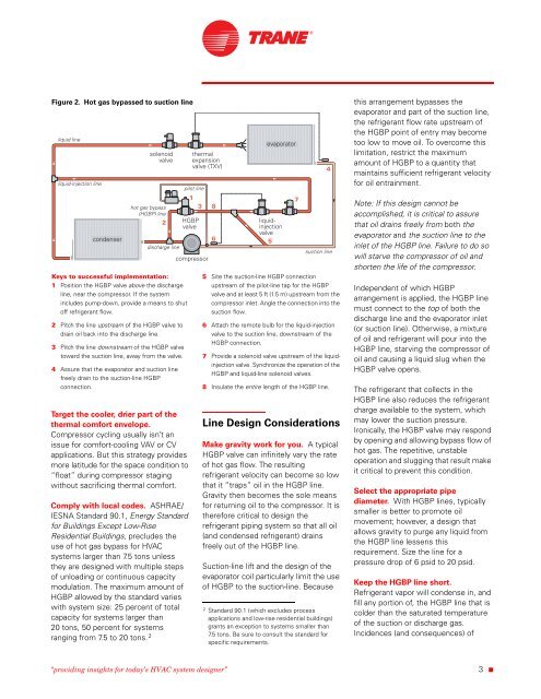
Figure 2. Hot gas bypassed to suction lineKeys to successful implementation:1 Position the HGBP valve above the dischargeline, near the compressor. If the systemincludes pump-down, provide a means to shutoff refrigerant flow.2 Pitch the line upstream of the HGBP valve todrain oil back into the discharge line.3 Pitch the line downstream of the HGBP valvetoward the suction line, away from the valve.4 Assure that the evaporator and suction linefreely drain to the suction-line HGBPconnection.Target the cooler, drier part of thethermal comfort envelope.Compressor cycling usually isn’t anissue for comfort-cooling VAV or CVapplications. But this strategy providesmore latitude for the space condition to“float” during compressor stagingwithout sacrificing thermal comfort.Comply with local codes. ASHRAE/IESNA Standard 90.1, Energy Standardfor Buildings Except Low-RiseResidential Buildings, precludes theuse of hot gas bypass for HVACsystems larger than 7.5 tons unlessthey are designed with multiple stepsof unloading or continuous capacitymodulation. The maximum amount ofHGBP allowed by the standard varieswith system size: 25 percent of totalcapacity for systems larger than20 tons, 50 percent for systemsranging from 7.5 to 20 tons. 25 Site the suction-line HGBP connectionupstream of the pilot-line tap for the HGBPvalve and at least 5 ft (1.5 m) upstream from thecompressor inlet. Angle the connection into thesuction flow.6 Attach the remote bulb for the liquid-injectionvalve to the suction line, downstream of theHGBP connection.7 Provide a solenoid valve upstream of the liquidinjectionvalve. Synchronize the operation of theHGBP and liquid-line solenoid valves.8 Insulate the entire length of the HGBP line.Line Design ConsiderationsMake gravity work for you. A typicalHGBP valve can infinitely vary the rateof hot gas flow. The resultingrefrigerant velocity can become so lowthat it “traps” oil in the HGBP line.Gravity then becomes the sole meansfor returning oil to the compressor. It istherefore critical to design therefrigerant piping system so that all oil(and condensed refrigerant) drainsfreely out of the HGBP line.Suction-line lift and the design of theevaporator coil particularly limit the useof HGBP to the suction-line. Because2 Standard 90.1 (which excludes processapplications and low-rise residential buildings)grants an exception to systems smaller than7.5 tons. Be sure to consult the standard forspecific requirements.this arrangement bypasses theevaporator and part of the suction line,the refrigerant flow rate upstream ofthe HGBP point of entry may becometoo low to move oil. To overcome thislimitation, restrict the maximumamount of HGBP to a quantity thatmaintains sufficient refrigerant velocityfor oil entrainment.Note: If this design cannot beaccomplished, it is critical to assurethat oil drains freely from both theevaporator and the suction line to theinlet of the HGBP line. Failure to do sowill starve the compressor of oil andshorten the life of the compressor.Independent of which HGBParrangement is applied, the HGBP linemust connect to the top of both thedischarge line and the evaporator inlet(or suction line). Otherwise, a mixtureof oil and refrigerant will pour into theHGBP line, starving the compressor ofoil and causing a liquid slug when theHGBP valve opens.The refrigerant that collects in theHGBP line also reduces the refrigerantcharge available to the system, whichmay lower the suction pressure.Ironically, the HGBP valve may respondby opening and allowing bypass flow ofhot gas. The repetitive, unstableoperation and slugging that result makeit critical to prevent this condition.Select the appropriate pipediameter. With HGBP lines, typicallysmaller is better to promote oilmovement; however, a design thatallows gravity to purge any liquid fromthe HGBP line lessens thisrequirement. Size the line for apressure drop of 6 psid to 20 psid.Keep the HGBP line short.Refrigerant vapor will condense in, andfill any portion of, the HGBP line that iscolder than the saturated temperatureof the suction or discharge gas.Incidences (and consequences) of“providing insights for today’s HVAC system designer”3 ■